Page is loading ...

OneGear 7.2 kV Motor Controller — Full-voltage,
Non-reversing
Bulletin Number 7712
User Manual
Original Instructions

Important User Information
Read this document and the documents listed in the additional resources section about installation, configuration, and
operation of this equipment before you install, configure, operate, or maintain this product. Users are required to
familiarize themselves with installation and wiring instructions in addition to requirements of all applicable codes, laws,
and standards.
Activities including installation, adjustments, putting into service, use, assembly, disassembly, and maintenance are
required to be carried out by suitably trained personnel in accordance with applicable code of practice.
If this equipment is used in a manner not specified by the manufacturer, the protection provided by the equipment may
be impaired.
In no event will Rockwell Automation, Inc. be responsible or liable for indirect or consequential damages resulting from
the use or application of this equipment.
The examples and diagrams in this manual are included solely for illustrative purposes. Because of the many variables and
requirements associated with any particular installation, Rockwell Automation, Inc. cannot assume responsibility or
liability for actual use based on the examples and diagrams.
No patent liability is assumed by Rockwell Automation, Inc. with respect to use of information, circuits, equipment, or
software described in this manual.
Reproduction of the contents of this manual, in whole or in part, without written permission of Rockwell Automation,
Inc., is prohibited
Throughout this manual, when necessary, we use notes to make you aware of safety considerations.
Labels may also be on or inside the equipment to provide specific precautions.
WARNING: Identifies information about practices or circumstances that can cause an explosion in a hazardous
environment, which may lead to personal injury or death, property damage, or economic loss.
ATTENTION: Identifies information about practices or circumstances that can lead to personal injury or death, property
damage, or economic loss. Attentions help you identify a hazard, avoid a hazard, and recognize the consequence.
IMPORTANT Identifies information that is critical for successful application and understanding of the product.
SHOCK HAZARD: Labels may be on or inside the equipment, for example, a drive or motor, to alert people that dangerous
voltage may be present.
BURN HAZARD: Labels may be on or inside the equipment, for example, a drive or motor, to alert people that surfaces may
reach dangerous temperatures.
ARC FLASH HAZARD: Labels may be on or inside the equipment, for example, a motor control center, to alert people to
potential Arc Flash. Arc Flash will cause severe injury or death. Wear proper Personal Protective Equipment (PPE). Follow ALL
Regulatory requirements for safe work practices and for Personal Protective Equipment (PPE).

Rockwell Automation Publication 7712-UM001D-EN-P - October 2017 3
Table of Contents
Preface
Introduction. . . . . . . . . . . . . . . . . . . . . . . . . . . . . . . . . . . . . . . . . . . . . . . . . . . 7
Summary of Changes . . . . . . . . . . . . . . . . . . . . . . . . . . . . . . . . . . . . . . . . . . . 7
Who Should Use this Manual . . . . . . . . . . . . . . . . . . . . . . . . . . . . . . . . . . . 7
Service and Maintenance. . . . . . . . . . . . . . . . . . . . . . . . . . . . . . . . . . . . . . . . 7
ArcShield Arc Flash Resistant Enclosure Features . . . . . . . . . . . . . . . . . 7
Controller Unit Identification . . . . . . . . . . . . . . . . . . . . . . . . . . . . . . . . . . 8
Additional Resources . . . . . . . . . . . . . . . . . . . . . . . . . . . . . . . . . . . . . . . . . . . 9
Chapter 1
General Information Environmental Conditions. . . . . . . . . . . . . . . . . . . . . . . . . . . . . . . . . . . . . 11
Product Dimensions and Weights . . . . . . . . . . . . . . . . . . . . . . . . . . . . . . 12
ArcShield Components Installation Requirements . . . . . . . . . . . . . . . 13
Chapter 2
Safety Interlock and Accessibility
Requirements
Recommended Torque Values. . . . . . . . . . . . . . . . . . . . . . . . . . . . . . . . . . 15
Open the Enclosure Doors . . . . . . . . . . . . . . . . . . . . . . . . . . . . . . . . . . . . . 16
Opening the Low Voltage Door . . . . . . . . . . . . . . . . . . . . . . . . . . . . 16
Opening the Medium Voltage Door. . . . . . . . . . . . . . . . . . . . . . . . . 17
Chapter 3
Start-up Procedure Contactor Inspection. . . . . . . . . . . . . . . . . . . . . . . . . . . . . . . . . . . . . . . . . . 19
Preliminary Checks. . . . . . . . . . . . . . . . . . . . . . . . . . . . . . . . . . . . . . . . . . . . 19
Testing Contactor Operation . . . . . . . . . . . . . . . . . . . . . . . . . . . . . . . . . . 20
Test Power Supply. . . . . . . . . . . . . . . . . . . . . . . . . . . . . . . . . . . . . . . . . 21
Operating Position . . . . . . . . . . . . . . . . . . . . . . . . . . . . . . . . . . . . . . . . 21
Chapter 4
Equipment Operation Power Lockout Procedure. . . . . . . . . . . . . . . . . . . . . . . . . . . . . . . . . . . . . . 27
Open Contactor. . . . . . . . . . . . . . . . . . . . . . . . . . . . . . . . . . . . . . . . . . . 27
Power Down Low Voltage Section . . . . . . . . . . . . . . . . . . . . . . . . . . 27
Selecting Power Source . . . . . . . . . . . . . . . . . . . . . . . . . . . . . . . . . . . . . . . . 28
Connecting Test Power. . . . . . . . . . . . . . . . . . . . . . . . . . . . . . . . . . . . . . . . 28
Racking Contactor Cart . . . . . . . . . . . . . . . . . . . . . . . . . . . . . . . . . . . . . . . 28
Operation of Motor Controller . . . . . . . . . . . . . . . . . . . . . . . . . . . . . . . . 30
Earthing Switch Operation. . . . . . . . . . . . . . . . . . . . . . . . . . . . . . . . . 30
Earthing Switch Positioning Indicators. . . . . . . . . . . . . . . . . . . . . . 31
Contactor Cart . . . . . . . . . . . . . . . . . . . . . . . . . . . . . . . . . . . . . . . . . . . . . . . 32
Connect LV Plug . . . . . . . . . . . . . . . . . . . . . . . . . . . . . . . . . . . . . . . . . . 32
Shutter Position Indicator. . . . . . . . . . . . . . . . . . . . . . . . . . . . . . . . . . 33

4 Rockwell Automation Publication 7712-UM001D-EN-P - October 2017
Table of Contents
Chapter 5
Maintenance Required Tools . . . . . . . . . . . . . . . . . . . . . . . . . . . . . . . . . . . . . . . . . . . . . . . 37
Maintenance of Industrial Control Equipment . . . . . . . . . . . . . . . . . . 37
Periodic Inspection . . . . . . . . . . . . . . . . . . . . . . . . . . . . . . . . . . . . . . . . 37
Contamination. . . . . . . . . . . . . . . . . . . . . . . . . . . . . . . . . . . . . . . . . . . . 38
Operating Mechanisms . . . . . . . . . . . . . . . . . . . . . . . . . . . . . . . . . . . . 38
Terminals. . . . . . . . . . . . . . . . . . . . . . . . . . . . . . . . . . . . . . . . . . . . . . . . . 38
Coils . . . . . . . . . . . . . . . . . . . . . . . . . . . . . . . . . . . . . . . . . . . . . . . . . . . . . 39
Pilot Lights . . . . . . . . . . . . . . . . . . . . . . . . . . . . . . . . . . . . . . . . . . . . . . . 39
Annual Maintenance Requirements . . . . . . . . . . . . . . . . . . . . . . . . . . . . 39
Remove Contactor Cart . . . . . . . . . . . . . . . . . . . . . . . . . . . . . . . . . . . . . . . 40
Remove and Replace Fuses . . . . . . . . . . . . . . . . . . . . . . . . . . . . . . . . . . . . . 43
Contactor Cart Maintenance . . . . . . . . . . . . . . . . . . . . . . . . . . . . . . . . . . 45
Replace the Vacuum Bottles . . . . . . . . . . . . . . . . . . . . . . . . . . . . . . . . 45
Calibrate the Overtravel and Contact Gap. . . . . . . . . . . . . . . . . . . 48
Lubricate the Contactor Cart. . . . . . . . . . . . . . . . . . . . . . . . . . . . . . . 50
Earthing Switch Maintenance . . . . . . . . . . . . . . . . . . . . . . . . . . . . . . . . . . 53
Inspect and Lubricate Earthing Switch Mechanism . . . . . . . . . . . 53
Ground Connection Inspection . . . . . . . . . . . . . . . . . . . . . . . . . . . . 55
Toggle Assembly Inspection . . . . . . . . . . . . . . . . . . . . . . . . . . . . . . . . 55
Earthing Switch Auxiliary Maintenance . . . . . . . . . . . . . . . . . . . . . . . . . 56
Auxiliary Contacts Replacement . . . . . . . . . . . . . . . . . . . . . . . . . . . . 56
Auxiliary Contacts Adjustment . . . . . . . . . . . . . . . . . . . . . . . . . . . . . 56
Earthing Switch Auxiliary Contacts Inspection . . . . . . . . . . . . . . 57
Appendix A
Spare Parts Typical Bulletin 7712 Parts . . . . . . . . . . . . . . . . . . . . . . . . . . . . . . . . . . . . 59
Appendix B
Certification Data Test Summary . . . . . . . . . . . . . . . . . . . . . . . . . . . . . . . . . . . . . . . . . . . . . . . . 61
High Voltage Controlgear Starter. . . . . . . . . . . . . . . . . . . . . . . . . . . 61
Appendix C
Troubleshooting Door Interlock Circumvention. . . . . . . . . . . . . . . . . . . . . . . . . . . . . . . . . 63
Earthing Switch to Door . . . . . . . . . . . . . . . . . . . . . . . . . . . . . . . . . . . 63
Door to Isolation Shutter . . . . . . . . . . . . . . . . . . . . . . . . . . . . . . . . . . 65
Appendix D
Mechanical Interlock for 7712 and
PowerFlex 7000 Drive
Keys. . . . . . . . . . . . . . . . . . . . . . . . . . . . . . . . . . . . . . . . . . . . . . . . . . . . . . . . . . 69
KD and KE Keys . . . . . . . . . . . . . . . . . . . . . . . . . . . . . . . . . . . . . . . . . . 69
KC Key . . . . . . . . . . . . . . . . . . . . . . . . . . . . . . . . . . . . . . . . . . . . . . . . . . 69
KA and KB Keys . . . . . . . . . . . . . . . . . . . . . . . . . . . . . . . . . . . . . . . . . . 69
KC Keys for doors . . . . . . . . . . . . . . . . . . . . . . . . . . . . . . . . . . . . . . . . 69
KD and KE Key for Output Cables Cabinet Door . . . . . . . . . . . 69
Transfer Block . . . . . . . . . . . . . . . . . . . . . . . . . . . . . . . . . . . . . . . . . . . . 70

Rockwell Automation Publication 7712-UM001D-EN-P - October 2017 5
Table of Contents
Connections . . . . . . . . . . . . . . . . . . . . . . . . . . . . . . . . . . . . . . . . . . . . . . . . . . 70
Motor Connection from 7791. . . . . . . . . . . . . . . . . . . . . . . . . . . . . . 70
Motor Connection from 7712. . . . . . . . . . . . . . . . . . . . . . . . . . . . . . 70
Interlock Operation Sequence (One Motor). . . . . . . . . . . . . . . . . . . . . 70
Initial Condition . . . . . . . . . . . . . . . . . . . . . . . . . . . . . . . . . . . . . . . . . . 70
To Run Drive . . . . . . . . . . . . . . . . . . . . . . . . . . . . . . . . . . . . . . . . . . . . . 70
To Run Bypass . . . . . . . . . . . . . . . . . . . . . . . . . . . . . . . . . . . . . . . . . . . . 71
To open Drive for Service . . . . . . . . . . . . . . . . . . . . . . . . . . . . . . . . . . 71
To open Output Cabinet . . . . . . . . . . . . . . . . . . . . . . . . . . . . . . . . . . 71
Interlock Operation Sequence (Two Motors) . . . . . . . . . . . . . . . . 71

6 Rockwell Automation Publication 7712-UM001D-EN-P - October 2017
Table of Contents
Notes:

Rockwell Automation Publication 7712-UM001D-EN-P - October 2017 7
Preface
Introduction
This user manual provides installation instructions and maintenance
procedures for the Rockwell Automation Bulletin 7712 ArcShield™ arc flash
resistant enclosure, medium voltage controller. The Bulletin 7712 structure
provides one complete MV controller unit.
Summary of Changes
This manual contains new and updated information as indicated in the
following table.
Who Should Use this Manual
This manual is intended for qualified service personnel responsible for
installing and maintaining medium voltage controllers. You should have
previous experience with, and an understanding of, electrical terminology,
procedures, required troubleshooting equipment, equipment protection
procedures and methods, and safety precautions. See safety related practices
contained in publication NFPA 70E, Standard for Electrical Safety in the
Work Place.
Service and Maintenance
For your convenience, Rockwell Automation Customer Support and
Maintenance (CSM), provides an efficient and convenient method of servicing
medium voltage products. Contact your local area support office to make
arrangements to have a qualified service representative come to your facility. A
complete listing of Area Support Offices may be obtained by calling your local
Rockwell Automation Distributor or Sales Office.
For Medium Voltage technical support on start-up or existing installations,
contact your Rockwell Automation representative. You can also call 1-519-
740-4790 for assistance Monday through Friday from 9:00 a.m. to 5:00 p.m.
(Eastern Time zone).
ArcShield Arc Flash Resistant
Enclosure Features
Built to minimize exposure to electrical hazards, the OneGear 7.2 kV motor
controller includes an optional earthing switch and fully interlocked
compartment doors to isolate the power source when an apparatus cell door is
open. The controller features ArcShield arc flash-resistant enclosures, which
provide arc-flash protection in accordance with the IEC 62271-200 Annex A
standard.
The controller is designed, manufactured and tested to meet or exceed the
applicable requirements of the latest standards published by the following
organizations:
• IEC 60470: High-voltage Alternating Current Contactors and
Contactor Based Motor-Starters.
Topic Page
Replaced Spare Parts List 59

8 Rockwell Automation Publication 7712-UM001D-EN-P - October 2017
Preface
• IEC 62271-100: High-voltage Switchgear and Control Gear, Circuit
Breakers
• IEC 62271-1: High-voltage Switchgear and Control Gear, Common
Specifications
• IEC 62271-200: High-voltage Switchgear and Control Gear
• IEC 62271-102: High-voltage Switchgear and Control Gear,
Disconnectors and Earthing Switches
• European Directives for Safety and EMC
•RoHS
Note: It is the responsibility of the customer and/or installer to know and meet
all local codes, standards, and OSHA requirements.
Controller Unit Identification
A nameplate is attached to the front door of the structure (see Figure 1). Refer
to the nameplate for information such as series number, section number,
enclosure type, unit ratings, and bus ratings.
Figure 1 - Typical Structure Nameplate
A nameplate is also found in the low voltage compartment (see Figure 2) with
specific unit and motor application information.

Rockwell Automation Publication 7712-UM001D-EN-P - October 2017 9
Preface
Figure 2 - Typical Unit/Motor Nameplate
Refer to these nameplates whenever you contact Rockwell Automation for
assistance. Be prepared to provide information such as series number, structure
series, unit series, diagram schematic, and catalog number.
Additional Resources
The following table lists publications that provide related information.
You can view or download publications at http://
www.rockwellautomation.com/literature/. To order paper copies of technical
documentation, contact your local Rockwell Automation distributor or sales
representative.
Resource Description
OneGear 7.2 kV Motor Controller - Full-voltage, Non-
reversing and Incoming Line Unit - Technical Data, 7712-
TD001
Provides technical specifications and an overview of the
features and functions provided by the controller and in-
coming line unit.
OneGear SMC Flex Solid-State Motor Controller (10…15
kV) Specification Guide, 7760-SR001
Provides a outline for the overall fabrication,
performance and functional requirements for a medium
voltage, reduced-voltage solid state motor controller
(RVSS) for use with induction and brush type
synchronous motors.
How to Successfully Apply Medium Voltage Soft
Starters, 1560E-WP023
Provides guidelines for selecting and applying medium
voltage starters.
SMC-Flex Controller with Pump Control,
150-WP003
Provides guidelines for applying the SMC-Flex controller
with pump control.
General Handling Procedures for Medium Voltage
Controllers Quick Start, MV-QS050
Provides basic information on installation site
preparation.
Medium Voltage Contactor 400A User Manual, 1502-
UM052
Provides general guidelines for the application,
installation, and maintenance of 400A medium voltage
vacuum contactors.

10 Rockwell Automation Publication 7712-UM001D-EN-P - October 2017
Preface
Notes:

Rockwell Automation Publication 7712-UM001D-EN-P - October 2017 11
Chapter 1
General Information
The chapter contains information essential for proper installation of the
OneGear™ 7.2 kV Bulletin 7712 medium voltage controller. Read all
information in this chapter before beginning the controller installation in
Chapter 2
.
Environmental Conditions
The standard controller is rated to operate in an ambient temperature range of
0…40 °C (32…104 °F) with a relative humidity of up to 95% (non
condensing). Higher ambient temperature conditions are supported with
factory assistance. The controller must be derated for ambient temperatures
above 40 ºC (104 °F).
The equipment operates at altitudes from 0…1000 m (3300 ft) above sea level,
without de-rating. For applications above 1000 m (3300 ft), the maximum
current and Basic Impulse Levels (B.I.L.) of the controllers and incoming line
unit shall be de-rated and vacuum contactors/breakers will be compensated for
operation at the specified altitude.
Rockwell Automation products use materials that comply with Class 1:
Industrial Clean Air sulphur environments as defined in IEC Standard 60654-
4 (Operating Conditions for Industrial-Process Measurement and Control
Equipment), and G1 as defined in ISA-S71.04-1985 (Environmental
Conditions for Process Measurement and Control Systems: Airborne
Contaminants).

12 Rockwell Automation Publication 7712-UM001D-EN-P - October 2017
Chapter 1 General Information
Product Dimensions and
Weights
Figure 3 - Controller Dimension Diagram
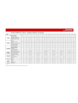
Table 1 - Approximate Dimensions and Weights
Bulletin No. Description Width Height
(1)
(1) The height dimension does not include the plenum (574 mm [22.60 in.]), which is removed for shipping and installed by the
customer. The total height of the unit including an installed plenum is 2674 mm (105.27 in.).
Depth Weight
7712 250 A (single fuse) FVNR
Controller
350 mm
(13.78 in.)
2200 mm
(86.71 in.)
1100 mm
(43.31 in.)
489 kg
(1075 lb)
7712 330 A (double fuse)
FVNR Controller
350 mm
(13.78 in.)
2200 mm
(86.71 in.)
1100 mm
(43.31 in.)
504 kg
(1108 lb)

Rockwell Automation Publication 7712-UM001D-EN-P - October 2017 13
General Information Chapter 1
ArcShield Components
Installation Requirements
The Bulletin 7712 ArcShield enclosure typically includes a pressure relief vent.
The pressure relief vent opens under arc flash conditions, allowing hazardous
flames and gases to exit the enclosure via plenum.
ATTENTION: The low voltage panel area is sealed to prevent flames and
gases from entering; however, suitable personal protective equipment (PPE)
must be used whenever working on live circuits.
ATTENTION: To ensure arc flash resistant integrity:
• The pressure relief vent must not be tampered with and must not be used as
a step.
• No alterations can be made to the ArcShield structure.
• All covers, plates, and hardware removed for installation or maintenance
purposes must be re-installed and properly secured. Failure to do so voids
the arc flash resistant integrity.
• Power cable entry points are to be treated as the boundary between a
hazardous location and sealed accordingly. Failure to do so voids the arc flash
resistant integrity.
• A plenum must be used to direct the arc flash energy to a suitable location.
Failure to do so voids the arc flash resistant integrity. See Publication 7712-
IN001for plenum installation instructions.
• All wiring between the low voltage panel and the power cell must be routed
through a suitable gland to ensure flames and gases are not transmitted into
this area (as fitted from factory).
• The medium voltage power cell doors must be properly secured, using the
handle mechanism (refer to instruction label on the power cell door and
page 16
). Failure to do so voids the arc flash resistance integrity.

14 Rockwell Automation Publication 7712-UM001D-EN-P - October 2017
Chapter 1 General Information
Notes:

Rockwell Automation Publication 7712-UM001D-EN-P - October 2017 15
Chapter 2
Safety Interlock and Accessibility
Requirements
Recommended Torque
Values
When installing line and load cables or enclosure access panels, use the
following torque specifications.
Table 2 - Hardware Torque Specifications
ATTENTION: This procedure requires contact with medium voltage
components. To avoid shock hazards, complete the Power Lockout procedure
on page 27
before servicing the equipment. Verify with a hot stick or
appropriate voltage measuring device that all circuits are voltage free. Failure
to do so may result in severe burns, injury or death.
IMPORTANT For general information on handling medium voltage controllers and
preparing the installation site, see publication MV-QS050
.
ATTENTION: Use suitable personal protective equipment (PPE) per local
codes or regulations. Failure to do so may result in severe burns, injury, or
death.
Hardware Size Tightening Torque Required
1/4 in. (M6) 6 ft•lb (8 N•m)
5/16 in. (M8) 12 ft•lb (16 N•m)
3/8 in. (M10) 20 ft•lb (22 N•m)
1/2 in. (M14) 48 ft•lb (65 N•m)
ATTENTION: Some components of this product incorporate Imperial
hardware. Rockwell Automation recommends the use of the appropriate
tools to successfully complete the maintenance procedures on these
components. If you cannot obtain such tools, contact your area Rockwell
Automation sales office for assistance.

16 Rockwell Automation Publication 7712-UM001D-EN-P - October 2017
Chapter 2 Safety Interlock and Accessibility Requirements
Open the Enclosure Doors
The controller contains separate low voltage and medium voltage
compartments.
Opening the Low Voltage Door
• Using an Allen key, turn the two 1/4-turn fasteners 90° clockwise and
swing the door to the left.
Close and secure the low voltage door in the reverse order of opening.
Figure 4 - Enclosure Compartments
IMPORTANT The medium voltage door is interlocked to the isolation shutter and/or the
earthing switch. The low voltage panel compartment and power cell are
separated by an isolation barrier.
ArecShield Plenum
Low Voltage Door
Medium Voltage Door
1/4-turn Fasteners

Rockwell Automation Publication 7712-UM001D-EN-P - October 2017 17
Safety Interlock and Accessibility Requirements Chapter 2
Opening the Medium Voltage Door
1. Electrically open the contactor by pressing the STOP button on the
controller or at the remote control location.
2. Move the contactor cart to the isolated position.
3. Ensure the earthing switch is closed (page 30
).
4. Lift the release handle and swing the door to the left.
Close and secure the medium voltage door in the reverse order of opening.
ATTENTION: This procedure requires contact with medium voltage
components. To avoid shock hazards, complete the Power Lockout procedure
on page 27
before servicing the equipment. Verify with a hot stick or
appropriate voltage measuring device that all circuits are voltage free. Failure
to do so may result in severe burns, injury or death.
IMPORTANT Failure to open the medium voltage door in the proper manner could
damage or jam the mechanical door interlocks. This may result in the
mechanical interlocks not operating as intended and may result in the door
becoming jammed in the closed position.
TIP This procedure is contained on a label on the door of the controller for your
reference.

18 Rockwell Automation Publication 7712-UM001D-EN-P - October 2017
Chapter 2 Safety Interlock and Accessibility Requirements
Notes:

Rockwell Automation Publication 7712-UM001D-EN-P - October 2017 19
Chapter 3
Start-up Procedure
Contactor Inspection
See Chapter 2 in Medium Voltage Contactor 400A, Publication 1502-UM050
or 1502-UM052
for information on pre-energization inspection, vacuum
bottle integrity test and insulation resistance test.
Preliminary Checks
• Contactor current and voltage ratings are correct for the attached load
•Control voltage is correct
• Protective relay settings are correct
• Heater elements (if provided) in the overload relay are secure and
undamaged
• All equipment is correctly grounded
• External power and control connections match the electrical diagrams
• All hardware is correctly reinstalled and torqued to the correct
specification (see Recommended Torque Values on page 15
)
• All barriers are replaced and in the correct position
• All fuses are the correct class, type, and rating
• Mechanical interlocks function properly
• Contactor cart functions properly
• Earthing switch functions properly
• Microprocessor-based protection relay is correctly programmed
• Enclosure interior is free from dirt, metal chips, loose hardware, and or
tools

20 Rockwell Automation Publication 7712-UM001D-EN-P - October 2017
Chapter 3 Start-up Procedure
Testing Contactor Operation
The contactor must be tested without any applied medium voltage. This
should be done for initial startup and after any maintenance is performed. This
test power supply should be within the IntelliVAC™ Vacuum Contactor
Controller specifications (1503-UM053
). CPT on the cart is not energized
when the contactor is in the test/withdrawn position.
Connect an appropriate power cord to the power receptacle in the low voltage
compartment (Figure 5
).
Figure 5 - Location of Control Switch and Auxiliary Power Receptacle
It is possible to open the MV door while the cart is in the test/withdrawn
position and the earthing switch is closed. The shutter behind the cart in the
MV compartment should be closed under this situation. This should be
confirmed after opening the MV door.
If the MV door cannot be opened smoothly, the shutter is not completely shut
off or the earthing switch is not completely closed.
ATTENTION: Always perform the power lockout procedure before servicing
equipment. Failure to do so may result in severe burns, injury or death.
ATTENTION: The following procedure requires racking the contactor cart to
its test position. To avoid potential of shock hazards, disconnect and lockout
incoming power before proceeding. Failure to lockout incoming power will
result in a live bus cell. Once the shutter between power cell and bus cell is
open, it may cause severe burns, injury or death. Rockwell Automation does
not assume any responsibility for injuries to personnel who have not
completed the following safety procedure prior to servicing the equipment.
/