Electric Controller & Mfg. (EC&M) DC Magnetic Contactor - Class 7004 Type MGO1 MGAO1, 300A 400A, SPNO, Size NEMA5 5A, Series A Installation guide
- Type
- Installation guide

7004-69
11/00
Columbia, SC, USA
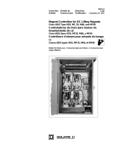
LINE-ARC® Single-Pole DC Contactor
NEMA Size 5, Normally Open
Size 5A, Normally Open
Class 7004 Type MGO-1 (300 A) &
MGAO-1 (400 A), Series A
Contactor de (cd) de un polo LINE-ARC®
Tamaños NEMA 5, normalmente abierto
Tamaños 5A, normalmente abierto
Clase 7004, tipos MGO-1 (300 Amperes) y
MGAO-1 (400 Amperes), serie A
Contacteur cc unipolaire LINE-ARC®
Tailles NEMA 5, normalement ouvert
Tailles 5A, normalement ouvert
Classe 7004 types MGO-1 (300 Ampères) et
MGAO-1 (400 Ampères), série A
Instruction Boletín de Directives
Bulletin instrucciones d'utilisation
Retain for future use. / Conservar para uso futuro. / À conserver pour
usage ultérieur.


7004-69 LINE-ARC®DC Contactor, NEMA Size 5, N.O. / Size 5A, N.O.
11/00 Introduction
3
© 1981–2000 Schneider Electric All Rights Reserved
ENGLISH
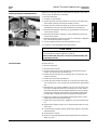
This size 5 single-pole contactor is a mill type clapper device, designed to
meetNEMAstandards. Toidentifycontactorparts (denotedbyparentheses),
refer to the parts list on page 12 and to the assembly drawing on page 13.
The operating coils are designed in accordance with NEMA standards to
withstand 110% of rated voltage continuously and to operate the contactor
successfully at 80% of rated voltage. Standardcoil voltages are115/120 Vdc
and 230/240 Vdc. Table 2 lists the ratings for standard operating coils. For
other coil voltages, refer to the crane control catalog, document
6100CT9702.
Electrical interlocks consist of stationary contacts mounted on the contact arm
support (23) and moving contacts attached to the bottom of the contact arm
assembly (22). A set of electrical interlocks contains one N.O. (normally open)
and one N.C. (normally closed) double-break contact. Make and break ratings
apply to double-throw contacts only when both the N.O. and N.C. contacts are
connected to the same polarity. The electrical interlock ratings (Table 3)
comply with NEMA standard ICS-2-125 (A600 and N600 Table Ratings).
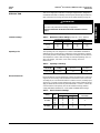
Table 1: Maximum Contactor Ratings @ 600 Vdc, +40 °C Ambient
Ratings DC Motor HP @ 230 Vdc DC Amperes
Size 5 Size 5A Size 5 Size 5A
Open 8 hour
Enclosed
Crane
75
67
110
110
100
150
300
270
400
400
360
533
Table 2: Operating Coil Ratings
Coil Part No. DC Voltage
Rating Nominal Resistance (Ω)
@+20°C Coil Amperes
@+20°C
51019-243-53
51019-243-56 230/240
115/120 1240
315 0.194
0.381
Table 3: Electrical Interlock Ratings
Rating Volts Maximum Current (A) Max. Continuous
Current (A)
Make Break
AC (A600)
120
240
480
600
60
30
15
12
6.0
3.0
1.5
1.2
10
DC (N600) 125
250
600
2.2
1.1
0.4
2.2
1.1
0.4 10
INTRODUCTION
HAZARDOUS VOLTAGE
Disconnect all power before working on equipment.
Failure to follow this instruction will result in death or serious
injury.
DANGER
Contactor Ratings
Operating Coils
Electrical Interlocks

LINE-ARC®DC Contactor, NEMA Size 5, N.O. / Size 5A, N.O. 7004-69
Installation 11/00
© 1981–2000 Schneider Electric All Rights Reserved
4
ENGLISH
The movable and stationary power contact tips are identical. Copper power
contact tips are standard. Optional silver-faced power contact tips are
recommended for applications where the contactor remains closed for long
periods of time. Silver-faced contact tips are standard on crane manual
magnetic disconnect switches and are optional on DC starters.
1. Unpack the contactor carefully. Remove the shipping tape, if used.
2. Inspect the nameplate data for correct equipment.Visually verify that the
contactor operating coil (39) is the correct voltage. The operating coil
circuit voltage may differ from the power circuit voltage.
3. Visually verify that all parts are undamaged and secure.
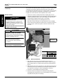
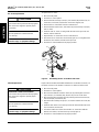
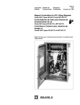
4. Mount the contactor vertically on a rigid support and secure it tightly,
using a plain washer against the contactor base. Provide the clearances
shown in Figure 1 above the top of the contactor and in front of the
arc chute.
Figure 1: Electrical Clearances
5. With all power disconnected, mount auxiliary devices (such as
mechanical or electrical interlocks) on the contactor. Install and adjust
these auxiliary devices according to the instructions provided with the
devices.
6. With all power disconnected, pivot the arc chute upward and operate the
contactor by hand. The contact tips (10) must meet squarely. If they do
not, align them according to “Contact Tip Alignment” on page 5.
7. Pivot the arc chute downward to its proper position.
8. Wire the contactor according to the control panel wiring diagram,
ensuringthatallconnectionsaresecure.Theoperatingcoilcircuitvoltage
may differ from the power circuit voltage.
Contact Tips
INSTALLATION
HAZARDOUS VOLTAGE
Disconnect power to the contactor before
installation, adjustments, maintenance, or
troubleshooting. Metal parts of the contactor
may be at line voltage.
Failure to follow this instruction will result
in death or serious injury.
DANGER
IMPROPER CONNECTION HAZARD
Failure to connect the operating coil to the
proper voltagemay cause improper contactor
operation or damage to the coil.
ARC CHUTE POSITION HAZARD
Do not operate the contactor with the
arc chute up.
Failure to follow these instructions can
result in injury or equipment damage.
CAUTION Y
X
NOTE: Shaded
area indicates
arcing clearances.
Dimension Clearance*
600 Vdc 240 Vdc
in. mm in. mm
X
Y2.0
6.0 51
152 2.0
2.8 51
71
*To grounded, uninsulated panel

7004-69 LINE-ARC®DC Contactor, NEMA Size 5, N.O. / Size 5A, N.O.
11/00 Adjustments
5
© 1981–2000 Schneider Electric All Rights Reserved
ENGLISH
Contactors may require contact alignment or adjustment of the mechanical
or electrical interlocks.
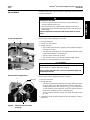
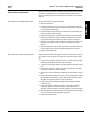
Refer to Figure 2 when aligning the contact tips.
1. Disconnect all power.
2. Pivot the arc chute upward.
3. Visually verify that:
— The movable contact tip (10) is properly seated against the ridge on
the auxiliary arm (13).
— Thestationarycontacttip(10)isseatedagainstthestationarycontact
support on the blowout coil assembly (2).
— The faces of the contact tips are flush.
— The contact tip surfaces are vertically and horizontally aligned.
4. Pivot the arc chute downward to its proper position.
Refer to Figure 3 when adjusting the electrical interlock.
1. Disconnect all power.
2. Visually verify that:
— The electrical interlock assembly (49) has proper follow-up (amount
of spring compression). With new electrical interlock contacts, the
moving contacts (52) must provide at least 1/16 in. (1.6 mm) follow-up
on each stationary contact when the contact arm reaches its limit of
travel (either completely closed or completely open).
— The N.C. electrical interlock contacts open before the power contact
tips close.
3. To adjust the electrical interlock follow-up, bend the stationary contacts
(56 and 57).
ADJUSTMENTS
HAZARDOUS VOLTAGE
• Contactors operated under load expel an arc. Stay away from a
contactor operating under load.
• Disconnect power to the contactor before aligning contact tips or
adjusting the electrical interlock. Metal parts of the contactor may be
at line voltage.
Failure to follow these instructions will result in death or serious
injury.
DANGER
Contact Tip Alignment
Figure 2: Contact Arm Assembly
13
10
2
ARC CHUTE POSITION HAZARD
Do not operate the contactor with the arc chute up.
Failure to follow this instruction can result in product damage and
shortened product life.
CAUTION
Electrical Interlock Adjustment
Figure 3: Electrical Interlock Contact
Follow-Up
Follow-up
52
49

LINE-ARC®DC Contactor, NEMA Size 5, N.O. / Size 5A, N.O. 7004-69
Maintenance 11/00
© 1981–2000 Schneider Electric All Rights Reserved
6
ENGLISH
The mechanical interlock is a tie bar which, when attached to two adjacent
contactors, ensures that only one ofthe two contactors can close at any one
time. Refer to Figure 4 when adjusting the mechanical interlock.
1. Disconnect all power.
2. Visually verify that the mechanical interlock allows the contact arm (22)
of either contactor to reach its limit of travel (either completely closed or
completely open) without binding.
3. Hold the contact arm of the left contactor fully closed and push the
contact arm of the right contactor closed until it is stopped by the
mechanical interlock.Verify that thereis a gap of at least 1/32 in. (0.8 mm)
but not more than 1/16 in. (1.5 mm) between the inside edge of the stop
bracket (44) and the back surface of the auxiliary arm (13). If the gap is
not within the limits, adjust the mechanical interlock as follows:
— Loosen the two screws that hold the mechanical interlock to the stop
bracket.
— Move the mechanical interlock until the desired gap is achieved.
4. Repeat step 3 above while holding the right contactor in the fully closed
position.
5. Push one contactor to the kiss position (when contact tips first touch) and
verify that the other contactor does not come to the kiss position at the
same time.
6. If both contactors come to the kiss position at the same time, repeat
steps 3–5, decreasing the gap. The gapmust be at least 1/32 in. (0.8 mm).
7. Visually verify that the mechanical interlock allows the contact arm of
either contactor to reach its limit of travel (either completely closed or
completely open) without binding.
Thissectiondescribesmaintenanceproceduresthatmayberequired.These
contactors require no lubrication because they have permanently lubricated,
oil-impregnated bearings.
Mechanical Interlock Adjustment
Figure 4: Mechanical Interlock Gap
MAINTENANCE
HAZARDOUS VOLTAGE
Disconnect power to the contactor before installation, adjustments,
maintenance, or troubleshooting. Metal parts of the contactor may be at
line voltage.
Failure to follow this instruction will result in death or serious
injury.
DANGER

7004-69 LINE-ARC®DC Contactor, NEMA Size 5, N.O. / Size 5A, N.O.
11/00 Maintenance
7
© 1981–2000 Schneider Electric All Rights Reserved
ENGLISH
Replace the contact tips when the contact follow-up (Figure 5) is less than 1/
16 in. (1.6 mm). To replace the contact tips:
1. Disconnect all power.
2. Pivot the arc chute upward.
3. Remove the silicon bronze hex-head cap screw (11), lock washer (12),
and movable contact tip (10) from the auxiliary arm (13).
4. Remove the silicon bronze hex-head cap screw (11), lock washer (12),
and stationary contact tip (10) from the blowout coil assembly (2).
5. Install the new stationary contact tip, securing it with the hex-head cap
screw and lock washer.
6. Install the new movable contact tip, securing it with the hex-head cap
screw and lock washer.
7. Manually operate the contactor and check the contact tips for alignment
(see “Contact Tip Alignment” on page 5).
8. Check the adjustment of the mechanical interlock, if used.
9. Pivot the arc chute downward to its proper position.
To replace the coil:
1. Disconnect all power.
2. Disconnect the coil leads.
3. Disconnect the top end of the shunt (21) by removing the hex-head
nut (20), lock washer (48), and washer (19).
4. Remove the hex-head nut (20), lock washer (48), set screw (26), and
contact arm pin (24).
5. Remove the contact arm assembly (22).
6. Remove the silicon bronze hex-head cap screw (35), lock washer (36),
core cap spacer (37), core cap (38), and coil (39) from the magnet frame
(41).
7. Install the new coil, securing it with the core cap, core cap spacer, and
lock washer. Tighten the hex-head screw.
Note: the core cap, which is
thicker than the spacer, must be installed against the coil (see Figure 7
on page 13).
Position the spring washer (40) so that the outside edge
(concave side) is against the coil and not against the magnet frame.
8. Replace the contact arm. Verify that the opening spring (29) is seated
properly over the hex-head cap screw (35).
9. Replace the contact arm pin (24). Tighten the set screw and hex-head
nut.
10.Verify that the auxiliary arm pin (27) is centered and that the set screw
(18) is tight.
11.Connect the top end of the shunt by replacing the washer, lock washer,
and hex-head nut.
12.Reconnect the coil leads.
13.Check the contact tip alignment and the adjustment of the mechanical
interlock, if used.
Contact Tip Inspection and Replacement
Figure 5: Contact Follow-Up
ARC CHUTE POSITION HAZARD
Do not operate the contactor with the arc chute up.
Failure to follow this instruction can result in product damage and
shortened product life.
CAUTION
Coil Replacement

LINE-ARC®DC Contactor, NEMA Size 5, N.O. / Size 5A, N.O. 7004-69
Maintenance 11/00
© 1981–2000 Schneider Electric All Rights Reserved
8
ENGLISH
To replace the arc chute:
1. Disconnect all power.
2. Pivot the arc chute upward.
3. Remove the hex-head cap screw (47), lock washer (48), washer (19), arc
chute wires, and shunt (21) from the contact arm support (23).
4. Remove the arc chute wires from the contactor base.
5. Removethehex-headnut(17),lockwasher(8),hex-headcapscrew(45),
and arc chute.
6. Install the new arc chute, securing it with the hex-head cap screw, lock
washer, and hex-head nut.
7. Reposition the arc chute wires on the contactor base.
8. Reconnect the arc chute wires and shunt (Figure 6), securing them with
the washer, lock washer, and hex-head cap screw.
9. Pivot the arc chute downward to its proper position.
Figure 6: Assembling the Arc Chute Wires and Shunt
Replace the shunt when the flexible braided wires are broken or burned, or if
the wires are loose in the terminal connectors on either end of the shunt.
1. Disconnect all power.
2. Pivot the arc chute upward.
3. Disconnect the bottom end of the shunt (21) by removing the hex-head
cap screw (47), lock washer (48), washer (19), and arc chute wires.
4. Disconnect the top end of the shunt by removing the hex-head nut (20),
lock washer (48), and washer (19).
5. Ensure that the auxiliary arm pin (27) is centered and the set screw (18)
is tight.
6. Install the new shunt. Secure the top end of the shunt with the hex-head
nut, lock washer, and washer.
7. Secure the bottom end of the shunt and the arc chute wires with the
washer, lock washer, and hex-head cap screw (Figure 6).
8. Pivot the arc chute downward to its proper position.
Arc Chute Replacement
IMPROPER CONNECTION HAZARD
The shunt must be positioned directly against
the contact arm support to provide proper
connection.
ARC CHUTE POSITION HAZARD
Do not operate the contactor with the
arc chute up.
Failure to follow these instructions can
result in in
j
ur
y
or e
q
ui
p
ment dama
g
e.
CAUTION
19 21
48
47
23
Arc Chute
Wires
Shunt Replacement
IMPROPER CONNECTION HAZARD
The shunt must be positioned directly against
the contact arm support to provide proper
connection.
ARC CHUTE POSITION HAZARD
Do not operate the contactor with the
arc chute up.
Failure to follow these instructions can
result in in
j
ur
y
or e
q
ui
p
ment dama
g
e.
CAUTION

7004-69 LINE-ARC®DC Contactor, NEMA Size 5, N.O. / Size 5A, N.O.
11/00 Maintenance
9
© 1981–2000 Schneider Electric All Rights Reserved
ENGLISH
Replace the electrical interlock contact tips when inspection shows that they
are burned or badly pitted. It is recommended that the entire electrical
interlock assembly be replaced. However, the contact tips only can also be
replaced.
To replace the electrical interlock assembly:
1. Disconnect all power.
2. Loosen the terminal clamps and screws (57) and remove the terminal
leads from thestationary contact assembly.Note the position of the leads
to ensure proper replacement.
3. Remove the pan-head screws (50), lock washers (51) and washers (59),
and the movable contact assembly.
4. Remove the pan-head screw (58) and the stationary contact assembly.
5. Install the new stationary contact assembly and replace the pan-head
screw(58).PositiontheassemblyasshowninFigure7onpage13.
6. Install the new movable contact assembly and replace the washers, lock
washers, and pan-head screws. Position the assembly as shown in
Figure 7.
7. Manually operate the contactor and check the moving contacts for follow-
up and sequencing (see “Electrical Interlock Adjustment” on page 5).
8. Replace the terminal leads.
After the electricalinterlock assemblyhas been removed from the contactor,
the contact tips can be replaced. To replace the electrical interlock contact
tips:
1. Compress the spring (54) and retainers (53), and slide out the movable
contact tips (52) from the movable contact assembly.
2. Compress the spring and retainers, and slide in the new movable contact
tips.
3. Remove the screws (55), washers (59), and top stationary contact tips
(57) from the stationary contact assembly.
4. Remove the screws and terminal clamps from the top stationary contact
tips.
5. Replace the terminal clamps and screws onto the top stationary contact
tips. Replace the top stationary contact tips onto the stationary contact
assembly, securing them with the screws and washers.
6. Remove the screws and terminal clamps from the bottom stationary
contact tips (56).
7. Replace the terminal clamps and screws onto the bottom stationary
contact tips. Replace the bottom stationary contact tips onto the
stationary contact assembly, securing them with the screws and washers.
8. Manually operate the contactor and check the movable contacts for follow-
up (see “Electrical Interlock Adjustment” on page 5).
9. Replace the terminal leads.
Electrical Interlock Replacement
Electrical Interlock Assembly Replacement
Electrical Interlock Contact Tip Replacement

LINE-ARC®DC Contactor, NEMA Size 5, N.O. / Size 5A, N.O. 7004-69
Maintenance 11/00
© 1981–2000 Schneider Electric All Rights Reserved
10
ENGLISH
To replace the opening spring:
1. Disconnect all power.
2. Pivot the arc chute upward.
3. Disconnect the top end of the shunt (21) by removing the hex-head nut
(20), lock washer (48), and washer (19).
4. Remove the hex-head nut (20), lock washer (48), and set screws (26),
and slide out the contact arm pin (24).
5. Remove the contact arm (22).
6. Remove the hex-head cap screws (31), lock washer (8), washers (9),
armature plate (30), and opening spring (29).
7. Install the new opening spring by inserting the narrow end of the spring
through the hole in the armature plate. Ensure that the wide end of the
spring is between the armature plate and the contact arm.
8. Secure the armature plate to the contact arm with the washers, lock
washers, and hex-head cap screws.
9. Verify that there is no gap between the armature plate and the contact
arm. This indicates that the opening spring is properly seated between
the armature plate and the contact arm.
10.Replace the contact arm assembly. Verify that the opening spring is
seated properly over the hex-head screw (35).
11.Replace the contact arm pin, set screw, lock washer, and hex-head nut.
Tightenthesetscrewandhex-headnut.
12.Secure the top end of the shunt with the washer, lock washer, and hex-
head nut.
13.Check the contact tip alignment and the adjustment of the mechanical
interlock, if used.
14.Pivot the arc chute downward to its proper position.
Opening Spring Replacement
ARC CHUTE POSITION HAZARD
Do not operate the contactor with the arc chute up.
Failure to follow this instruction can result in product damage and
shortened product life.
CAUTION

7004-69 LINE-ARC®DC Contactor, NEMA Size 5, N.O. / Size 5A, N.O.
11/00 Troubleshooting
11
© 1981–2000 Schneider Electric All Rights Reserved
ENGLISH
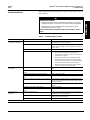
When troubleshooting, refer to page 3 for contactor ratings (Table 1) and coil
ratings (Table 2).
Table 4: Troubleshooting Procedure
Problem Possible Causes Corrective Action
The contacts do not close
or operation is sluggish. Improper or inoperative operating coil Visually verify the coil part number. Measure the resistance
to determine if the coil is inoperative.
Low control circuit voltage
*
Measure the control circuit voltage. It must be at least 80%
of the rated coil voltage. If it is 0, the problem is elsewhere
in the circuit.
Loose connection in the control circuit Inspect the connections. Tighten if loose.
Mechanical interference or binding Inspect for mechanical interference or binding:
— Disconnect the mechanical interlock from the
contactor that is binding (see “Mechanical Interlock
Adjustment” on page 6).
— Ensure that the tie bar is not causing the binding.
— Manually close the contact arm and verify that the
cap screw head (35) on the core of the magnet frame
assembly clears the hole in the armature plate.
— Manually close the contact arm and verify that the
auxiliary arm bearings are not binding.
The contact tips overheat,
short tip life. Loose connections Inspect the contact tips and shunt connections. Tighten if
loose.
The movable or stationary contact tip is not properly
aligned. Align the contact tips. See page 5.
There is foreign matter on the contact surfaces. Remove all foreign matter.
The contact tips are worn beyond the recommended
limits. Replace the contact tips. See page 7.
The contact surfaces are severely scored or burned. Ensure that the arc chute wires are connected to the contact
arm supportandarenotbroken.Inspectthecontactsurfaces
and file as required.
The arc chute is improperly installed. Verify that the arc chute is pivoted to the full downward
position.
The auxiliary arm spring is inoperative. Replace the spring.
Normal load currents are below 5% of rated contactor
current. Use a smaller size contactor.
The operating coil
overheats. Improper or inoperative coil Visually verify the coil part number. Measure the resistance
to determine if the coil is inoperative.
High voltage condition on the coil
*
Measure the control circuit voltage. It must not exceed
110% of the rated coil voltage.
Loose connection at the coil terminals Check the connections. Tighten if loose.
*See the danger statement above.
TROUBLESHOOTING
HAZARDOUS VOLTAGE
• Troubleshooting procedures marked with an asterisk (*) require the
application of power. Do not touch the contactor with power applied.
• Disconnect power to the contactor before performing any other
troubleshooting corrective action.
Failure to follow these instructions will result in death or serious
injury.
DANGER

LINE-ARC®DC Contactor, NEMA Size 5, N.O. / Size 5A, N.O. 7004-69
Ordering Instructions 11/00
© 1981–2000 Schneider Electric All Rights Reserved
12
ENGLISH
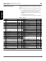
Specify the quantity, part number, and description of the part, giving the
complete nameplate data of the contactor. To identify parts, see Figure 7 on
page 13.
NOTE: The following modification kits are also available for this contactor:
— Class 9999 Type MM3 mechanical interlock kit for two single-pole
normally-open or two double-pole normally-open contactors
— Class 9999 Type MT3 tie bar kit for two single-pole normally-open
contactors
— Class 9999 Type MK2 pneumatic timer kit
— Class 9999 Type ML2 power lug kit, consisting of 4 clam shell lugs
Table 5: Parts List
Item Description Part Number Qty Item Description Part Number Qty
1 Arc chute 51019-217-50 1 30 Armature plate 51019-234-01 1
2Blowout coil assembly
Size 5
Size 5A 51019-205-50
51019-157-50 131 5/16"-18 x 5/8" hex-head cap screw 2
32 5/16" plain washer 2
3 Blowoutcoil guard 51019-237-01 1 33 Nameplate 1
41/4"-20 x 1/2" pan-head screw with captive lock washer 534 #6-32x
1/4" pan-head screw 2
51/4"-20 x 7/8" slotted hex-head cap screw 235 5/16"-18 x 3/4" silicon bronze hex-head capscrew 21407-22240 1
61/4" lock washer 236 5/16" silicon bronze lock washer 23711-22200 1
75/16"-18x1"slottedhex-headcapscrew 2 37 Core cap spacer, phosphor bronze 50502-006-11 1
85/16" lock washer 10 38 Core cap, steel 50502-006-10 1
91/4"-20 x 3/8" flat head brass screw 21203-20120 1 39 Operating coil, 230/240 Vdc
Operating coil, 115/120 Vdc 51019-243-53
51019-243-56 1
1
10 Contact tip kit (2 sets of tips & hardware)
Copper
Silver
Class 9998 Type
MG1
Class 9998 Type
MG2
1
1
40 Spring washer 51019-041-01 1
41 Magnet frame 51019-223-50 1
42 Contactor base 51019-238-50 1
11 3/8"-16 x 7/8" silicon bronze hex-head cap screw 21407-24280 2 43 5/16"-18 x 1/2" hex-head cap screw 2
12 3/8" silicon bronze lock washer 23711-22400 2 44 Stop bracket 51019-256-50 1
13 Auxiliary arm 51019-255-50 1 45 5/16"-18 x 2-1/2" hex-head capscrew 1
14 Auxiliary arm spring 50502-602-44 1 46 5/16"-18 x 3/4"slottedhex-headcapscrew 2
15 Auxiliary arm spring retainer 51019-239-01 1 47 3/8"-16 x 7/8" hex-head cap screw 21401-24280 1
16 5/16"-18 x 2" hex-head cap screw 148 3/8" lock washer 23701-00240 1
17 5/16"-18 hex-head nut 2
49
Electricalinterlock kit
Bulk pack of 5 sets of replacement interlock contacts,
includes:
10 movable contact tips (item 52), 10 bottom stationary
contacttips(item 56),10topstationary contact tips(item
57), 4 spring retainers (item 53) & 2 springs (item 54)
Class 9999, Type
MX1
51075-038-54 1
1
18 3/8"-16 x 2" headless slotted halfdog point set screw 21802-24640 1
19 3/8" plain washer 2
20 3/8"-16 hex-head nut 2
21 Shunt
Size 5
Size 5A 51019-204-50
51019-204-51 150 #10-24 x 1" pan-head screw 2
51 #10 lock washer 2
22 Contactarm 51019-214-50 1 52 Movablecontacttip 2
23 Contactarm support 51019-230-01 1 53 Spring retainer 2
24 Contactarm pin 51019-251-07 1 54 Spring 1
25 Bearing 29005-32220 2 55 #10-24x 1/2" pan-head screw with captive lock washer 1
26 3/8"-16 x 1" headless slotted half dog point set screw 21802-24320 1 56 Bottom stationary contacttip 2
27 Auxiliary arm pin 51019-251-05 1 57 Top stationary contact tip 2
28 Bearing 29005-24161 2 58 #10-24 x 1/2" captive screw assembly with long shank &
captive lock washer 1
29 Opening spring 50502-602-13 1 59 #10 plain washer 3
Obtain standard hardware, listed without Square D part number, from a local hardware supplier.
Parts recommended for general maintenance.
ORDERING INSTRUCTIONS

7004-69 LINE-ARC®DC Contactor, NEMA Size 5, N.O. / Size 5A, N.O.
11/00 Exploded Assembly Drawing
13
© 1981–2000 Schneider Electric All Rights Reserved
ENGLISH
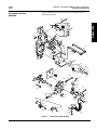
Figure 7 identifies items in the parts list and in the maintenance and
adjustment procedures.
Figure 7: Contactor Assembly Drawing
EXPLODED ASSEMBLY
DRAWING
45
8
17
1
654
44
42 3
9843
87
10
12
11
4
41
40
39
38 37
36
35
11
12
10
13
30
29
23
8
46
26 48 20 22
32
8
28
28 27
14
16
15
31
33
34
25
24
49
58 57
56 59
55 54
53 52 50
51
59
19
4847 21
18
8
17 19
48 20
2

7004-69 11/00
Replaces 50006-369-09, 50006-369-19, and
7004-80.
7004-69 11/00
Reemplaza 50006-369-09, 50006-369-19 y
7004-80).
7004-69 11/00
Remplace 50006-369-09, 50006-369-19 et
7004-80.
Square D Company
P.O. Box 9247
Columbus, SC 29290
1-888-411-8326
www.squared.com
Importado en México por:
Schneider Electric México, S.A. de C.V.
Calz. J. Rojo Gómez 1121-A
Col. Gpe. del Moral 09300 México, D.F.
Tel. 5804-5000
www.schneider-electric.com.mx
Schneider Canada Inc.
19 Waterman Avenue, M4B 1 Y2
Toronto, Ontario
(416) 752-8020
www.schneider-electric.ca
LINE-ARC®DC Contactor, NEMA Size 5, N.O. / Size 5A, N.O. /
Contactor de cd LINE-ARC®, tamaños NEMA 5 y tamaños 5A, N.A. /
Contacteur cc unipolaire LINE-ARC®, NEMA tailles 5 et tailles 5A, N.O.
FRANÇAIS
-
 1
1
-
 2
2
-
 3
3
-
 4
4
-
 5
5
-
 6
6
-
 7
7
-
 8
8
-
 9
9
-
 10
10
-
 11
11
-
 12
12
-
 13
13
-
 14
14


Electric Controller & Mfg. (EC&M) DC Magnetic Contactor - Class 7004 Type MGO1 MGAO1, 300A 400A, SPNO, Size NEMA5 5A, Series A Installation guide
- Type
- Installation guide
Ask a question and I''ll find the answer in the document
Finding information in a document is now easier with AI
Related papers
-
 Electric Controller & Mfg. (EC&M) 7004-61 ECM Size 1 and 2 NO Contactor Installation guide
-
 Electric Controller & Mfg. (EC&M) DC Magnetic Contactor - Class 7004 Type MGAO3, 400A, SPNC, Size 5a, Series A Installation guide
-
 Electric Controller & Mfg. (EC&M) DC Magnetic Contactor - Class 7004 Type MGO3, 300A, SPNC, Size NEMA5, Series A Installation guide
-
 Electric Controller & Mfg. (EC&M) Magnet Controller - Class 6815 Type M135, M175, MF135, MF175, 60-135A 85-175A Installation guide
-
 Electric Controller & Mfg. (EC&M) Magnet Controller - Class 6815 Type M35, M60, MF35, MF60, 15-35 25-60A Installation guide
-
 Electric Controller & Mfg. (EC&M) DC Installation guide


Other documents
-
Lincoln Electric SAF-600 Operating instructions
-
Lincoln Electric MECH. Travel Power Pack Operating instructions
-
Eaton 36-inch wide vacuum-break starters rated 360 amperes, 7200 volts, slide-out type Operating instructions
-
 Rockwell Automation Allen-Bradley 7712 User manual
-
Allen-Bradley 1512B User manual
-
-
-
-
-
