Page is loading ...

Medium Voltage Controllers Bulletin 1512A 800A
One-High Cabinet Standard and Arc Resistant Enclosure
Catalog Numbers 1512A, 1512AT, 1512DM, 1512M
User Manual

Important User Information
Read this document and the documents listed in the additional resources section about installation, configuration, and
operation of this equipment before you install, configure, operate, or maintain this product. Users are required to
familiarize themselves with installation and wiring instructions in addition to requirements of all applicable codes, laws,
and standards.
Activities including installation, adjustments, putting into service, use, assembly, disassembly, and maintenance are required
to be carried out by suitably trained personnel in accordance with applicable code of practice.
If this equipment is used in a manner not specified by the manufacturer, the protection provided by the equipment may be
impaired.
In no event will Rockwell Automation, Inc. be responsible or liable for indirect or consequential damages resulting from the
use or application of this equipment.
The examples and diagrams in this manual are included solely for illustrative purposes. Because of the many variables and
requirements associated with any particular installation, Rockwell Automation, Inc. cannot assume responsibility or
liability for actual use based on the examples and diagrams.
No patent liability is assumed by Rockwell Automation, Inc. with respect to use of information, circuits, equipment, or
software described in this manual.
Reproduction of the contents of this manual, in whole or in part, without written permission of Rockwell Automation,
Inc., is prohibited.
Throughout this manual, when necessary, we use notes to make you aware of safety considerations.
Labels may also be on or inside the equipment to provide specific precautions.
Allen-Bradley, Rockwell Software, Rockwell Automation, and TechConnect are trademarks of Rockwell Automation, Inc.
Trademarks ArcShield™, IntelliVAC™ Control, IntelliVAC™, IntelliVAC™ Plus not belonging to Rockwell Automation are property of their respective companies.
WARNING: Identifies information about practices or circumstances that can cause an explosion in a hazardous environment,
which may lead to personal injury or death, property damage, or economic loss.
ATTENTION: Identifies information about practices or circumstances that can lead to personal injury or death, property
damage, or economic loss. Attentions help you identify a hazard, avoid a hazard, and recognize the consequence.
IMPORTANT
Identifies information that is critical for successful application and understanding of the product.
SHOCK HAZARD: Labels may be on or inside the equipment, for example, a drive or motor, to alert people that dangerous
voltage may be present.
BURN HAZARD: Labels may be on or inside the equipment, for example, a drive or motor, to alert people that surfaces may
reach dangerous temperatures.
ARC FLASH HAZARD: Labels may be on or inside the equipment, for example, a motor control center, to alert people to
potential Arc Flash. Arc Flash will cause severe injury or death. Wear proper Personal Protective Equipment (PPE). Follow ALL
Regulatory requirements for safe work practices and for Personal Protective Equipment (PPE).

Rockwell Automation Publication 1512A-UM102C-EN-P - November 2015 3
Summary of Changes
This manual contains new and updated information.
New and Updated
Information
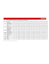
This table contains the changes that are made to this revision.
Topic Page
Changed description for 1512DM and 1512M Bulletin Numbers 9
Modified figure Typical Structure Nameplate. 10
Modified figure Typical Unit Nameplate. 10
Modified figure Access to Power Bus from Side and Rear Cabinet Typical. 16
Modified information in Figure 14 for current transformer. 20
Modified figure Access to Low Voltage Compartments, Arc Resistant. 23
Added steps to Opening the Medium Voltage Door. 24
Added All MV doors must be securely bolted closed before the ArcShield latch
handles are rotated.
25
Added Important table. 26
Added Important table. 27
Added figures Low Voltage Panel, Access to Power Bus with Low Voltage Panel
Rotated, Removal Of Access Panel with Low Voltage panel Rotated, Removal of
Low Voltage Barriers, and Power Bus with Bottom Access Barrier Removed.
30 … 32
Modified Access Power Bus Front Access - Top Entry procedure. 30
Added Typical Ground Bus Splicing Configuration (Front View) illustration. 37
Modified Important table. 43
Added Attention table. 44
Modified figures Door Interlock Lever, Inspecting Isolation Switch in Open
position, Contactor Voltage Checkpoints, Isolation Switch Voltage, Removing the
Contactor Front View), Closing Contactor Manually (some parts not shown),
Isolation Switch Lubrication Points, Isolation Switch Grounding Adjustment,
Location of ISa and ISb Auxiliary Contacts, Adjusting Auxilary Contacts (ISa
Auxiliary Contacts shown).
44 … 57
Added part numbers 80178-750-51, 80158-147-52, PN-272006. 61
Increased the unit quantity of PN-272006 61
Added 50 kA to ArcShield™ Unit Information. 63
Added Attention and Warning Tables. 73
Added Attention and Warning Tables. 82

4 Rockwell Automation Publication 1512A-UM102C-EN-P - November 2015
Summary of Changes
Notes:

Rockwell Automation Publication 1512A-UM102C-EN-P - November 2015 5
Table of Contents
Chapter 1
General Information
Scope . . . . . . . . . . . . . . . . . . . . . . . . . . . . . . . . . . . . . . . . . . . . . . . . . . . . . . . . . . . . . 9
Starter Identification . . . . . . . . . . . . . . . . . . . . . . . . . . . . . . . . . . . . . . . . . . . . . . . 9
Recommended Torque Values . . . . . . . . . . . . . . . . . . . . . . . . . . . . . . . . . . . . 10
Chapter 2
Installation - Standard Enclosure (Not
Arc Resistant)
Door Opening Procedure . . . . . . . . . . . . . . . . . . . . . . . . . . . . . . . . . . . . . . . . . 11
Opening the Low Voltage Doors. . . . . . . . . . . . . . . . . . . . . . . . . . . . . . . 11
Opening the Medium Voltage Doors . . . . . . . . . . . . . . . . . . . . . . . . . . . . . . 12
Anchoring. . . . . . . . . . . . . . . . . . . . . . . . . . . . . . . . . . . . . . . . . . . . . . . . . . . . . . . 13
Joining the Sections . . . . . . . . . . . . . . . . . . . . . . . . . . . . . . . . . . . . . . . . . . 14
Access to the Power Bus . . . . . . . . . . . . . . . . . . . . . . . . . . . . . . . . . . . . . . . . . . 15
Rear Access . . . . . . . . . . . . . . . . . . . . . . . . . . . . . . . . . . . . . . . . . . . . . . . . . . 15
Side Access. . . . . . . . . . . . . . . . . . . . . . . . . . . . . . . . . . . . . . . . . . . . . . . . . . . 16
Front Access – Top Incoming Load Cables . . . . . . . . . . . . . . . . . . . . . 17
Front Access – Bottom Incoming Line Cables . . . . . . . . . . . . . . . . . . 19
Load Cable Connections . . . . . . . . . . . . . . . . . . . . . . . . . . . . . . . . . . . . . . . . . 19
Chapter 3
Installation – Arc Resistant Enclosure
(ArcShield™)
Door Opening Procedure . . . . . . . . . . . . . . . . . . . . . . . . . . . . . . . . . . . . . . . . . 23
Opening the Low Voltage Doors. . . . . . . . . . . . . . . . . . . . . . . . . . . . . . . 23
Opening the Medium Voltage Doors. . . . . . . . . . . . . . . . . . . . . . . . . . . 24
Anchoring. . . . . . . . . . . . . . . . . . . . . . . . . . . . . . . . . . . . . . . . . . . . . . . . . . . . . . . 26
Access Power Bus . . . . . . . . . . . . . . . . . . . . . . . . . . . . . . . . . . . . . . . . . . . . . . . . 28
Rear Access . . . . . . . . . . . . . . . . . . . . . . . . . . . . . . . . . . . . . . . . . . . . . . . . . . 28
Side Access. . . . . . . . . . . . . . . . . . . . . . . . . . . . . . . . . . . . . . . . . . . . . . . . . . . 28
Front Access – Top Entry . . . . . . . . . . . . . . . . . . . . . . . . . . . . . . . . . . . . . 30
Chapter 4
Common Installation
Bus Splicing . . . . . . . . . . . . . . . . . . . . . . . . . . . . . . . . . . . . . . . . . . . . . . . . . . . . . 35
Power Bus . . . . . . . . . . . . . . . . . . . . . . . . . . . . . . . . . . . . . . . . . . . . . . . . . . . 35
Insulated Power Bus Splicing . . . . . . . . . . . . . . . . . . . . . . . . . . . . . . . . . . 36
Ground Bus. . . . . . . . . . . . . . . . . . . . . . . . . . . . . . . . . . . . . . . . . . . . . . . . . . 37
Incoming Line Cable Connections . . . . . . . . . . . . . . . . . . . . . . . . . . . . . . . . 37
Hi-Pot and Megger Test . . . . . . . . . . . . . . . . . . . . . . . . . . . . . . . . . . . . . . . . . . 38
Start-up Procedure . . . . . . . . . . . . . . . . . . . . . . . . . . . . . . . . . . . . . . . . . . . . . . . 39
Vacuum Contactor Inspection . . . . . . . . . . . . . . . . . . . . . . . . . . . . . . . . 39
Preliminary Checks. . . . . . . . . . . . . . . . . . . . . . . . . . . . . . . . . . . . . . . . . . . 39
Testing the Contactor Operation . . . . . . . . . . . . . . . . . . . . . . . . . . . . . . 40
Chapter 5
Maintenance
Tool Requirements. . . . . . . . . . . . . . . . . . . . . . . . . . . . . . . . . . . . . . . . . . . . . . . 43
Door Interlock Circumvention. . . . . . . . . . . . . . . . . . . . . . . . . . . . . . . . . . . . 44
Power Lockout Procedure . . . . . . . . . . . . . . . . . . . . . . . . . . . . . . . . . . . . . . . . 45

6 Rockwell Automation Publication 1512A-UM102C-EN-P - November 2015
Table of Contents
Fuse Removal and Replacement . . . . . . . . . . . . . . . . . . . . . . . . . . . . . . . . . . . 48
Bolt-on Fuses. . . . . . . . . . . . . . . . . . . . . . . . . . . . . . . . . . . . . . . . . . . . . . . . . 48
Bolt-on Fuse Removal and Installation . . . . . . . . . . . . . . . . . . . . . . . . . 49
Contactor Maintenance. . . . . . . . . . . . . . . . . . . . . . . . . . . . . . . . . . . . . . . . . . . 49
Removing the Contactor . . . . . . . . . . . . . . . . . . . . . . . . . . . . . . . . . . . . . . 49
Contactor Interlock Rod Adjustment . . . . . . . . . . . . . . . . . . . . . . . . . . . . . . 51
Reduce the Gap Distance. . . . . . . . . . . . . . . . . . . . . . . . . . . . . . . . . . . . . . 52
Increase the Gap Distance . . . . . . . . . . . . . . . . . . . . . . . . . . . . . . . . . . . . . 52
Isolation Switch Mechanism Inspection and Lubrication . . . . . . . . . . . . 53
Isolation Switch Mechanism Grounding Adjustment. . . . . . . . . . . . . . . . 54
Auxiliary Contacts Inspection and Replacement . . . . . . . . . . . . . . . . . . . . 55
Isolation Switch Auxiliary Contacts. . . . . . . . . . . . . . . . . . . . . . . . . . . . . . . . 57
Adjusting the Normally Open (ISa) Contacts . . . . . . . . . . . . . . . . . . 57
Adjusting the Normally Closed (ISb) Contacts. . . . . . . . . . . . . . . . . . 58
Adjusting the Change of State Point. . . . . . . . . . . . . . . . . . . . . . . . . . . . 58
Emergency Circumvention Procedure for Power Cell Entry . . . . . . 59
Chapter 6
Spare Parts
Spare Parts List. . . . . . . . . . . . . . . . . . . . . . . . . . . . . . . . . . . . . . . . . . . . . . . . . . . 61
Appendix A
ArcShield™ Unit Information
Overview . . . . . . . . . . . . . . . . . . . . . . . . . . . . . . . . . . . . . . . . . . . . . . . . . . . . . . . . 63
ArcShield Design . . . . . . . . . . . . . . . . . . . . . . . . . . . . . . . . . . . . . . . . . . . . . 63
Exhaust Systems: Chimney or Plenum Option . . . . . . . . . . . . . . . . . . . . . . 64
Plenum Information . . . . . . . . . . . . . . . . . . . . . . . . . . . . . . . . . . . . . . . . . . 64
Plenum Exhaust Considerations . . . . . . . . . . . . . . . . . . . . . . . . . . . . . . . . . . . 65
Additional Notes . . . . . . . . . . . . . . . . . . . . . . . . . . . . . . . . . . . . . . . . . . . . . . . . . 68
Chimney Information . . . . . . . . . . . . . . . . . . . . . . . . . . . . . . . . . . . . . . . . . . . . 68
Chimney Exhaust Considerations . . . . . . . . . . . . . . . . . . . . . . . . . . . . . . . . . 68
Appendix B
ArcShield™ Plenum Installation
Instructions
Recommended Torque Values. . . . . . . . . . . . . . . . . . . . . . . . . . . . . . . . . . . . . 69
Plenum Bracing . . . . . . . . . . . . . . . . . . . . . . . . . . . . . . . . . . . . . . . . . . . . . . . . . . 69
General Plenum Layout for ArcShield Line-up. . . . . . . . . . . . . . . . . . . . . . 71
STEP 1 – Mounting a Single Plenum . . . . . . . . . . . . . . . . . . . . . . . . . . . . . . 72
Cabinet Preparation . . . . . . . . . . . . . . . . . . . . . . . . . . . . . . . . . . . . . . . . . . 73
Plenum Placement on Structure. . . . . . . . . . . . . . . . . . . . . . . . . . . . . . . . 74
STEP 2 – Alignment of “Side-by-Side” Plenums . . . . . . . . . . . . . . . . . . . . 74
STEP 3 – Sequence of Final Assembly. . . . . . . . . . . . . . . . . . . . . . . . . . . . . . 75
STEP 4 – Closing the Front of the Plenum Sections. . . . . . . . . . . . . . . . . 76
STEP 5 – Extension and Elbow Assembly . . . . . . . . . . . . . . . . . . . . . . . . . . 76
STEP 6 – Mounting Extension/Elbow to Plenum “Line-up” . . . . . . . . . 77
STEP 7 – Additional Mounting Support . . . . . . . . . . . . . . . . . . . . . . . . . . . 79

Rockwell Automation Publication 1512A-UM102C-EN-P - November 2015 7
Table of Contents
Appendix C
ArcShield™ Chimney Installation
Instructions
Recommended Torque Values . . . . . . . . . . . . . . . . . . . . . . . . . . . . . . . . . . . . 81
General Plenum Layout for ArcShield Line-up . . . . . . . . . . . . . . . . . . . . . 81
Cabinet Preparation . . . . . . . . . . . . . . . . . . . . . . . . . . . . . . . . . . . . . . . . . . 82
Chimney Placement on Structure. . . . . . . . . . . . . . . . . . . . . . . . . . . . . . 83

8 Rockwell Automation Publication 1512A-UM102C-EN-P - November 2015
Table of Contents
Notes:

Rockwell Automation Publication 1512A-UM102C-EN-P - November 2015 9
Chapter 1
General Information
Scope
This document pertains to the Rockwell Automation® Bulletin 1512A medium
voltage (MV) controller. The Bulletin 1512A structure provides one complete
MV controller unit.
The product Bulletin numbers that are covered by this document are:
• 1512A 800A FVNR controller
• 1512AT 800A Transformer Feeder
This document can also be used as a reference guide for these Bulletin numbers:
• 1512DM 800A (FVIO) Input Contactor with Output Isolator
• 1512M 800A (FVOP) Output Bypass Controller
Starter Identification
A nameplate is attached to the right-side flange of the structure (Figure 1). See
the nameplate for information such as series number, section number, NEMA
(National Electrical Manufacturers Association) enclosure type, unit ratings, and
bus ratings.
IMPORTANT
This document is used for all Bulletin 800 amp1512A unit types, including arc
resistant (ArcShield™) units. Important information specifically for ArcShield
units can be found in Appendix A, B, and C.
ATTENTION: See the information in Appendix A, B, and C to install and
maintain ArcShield arc resistant units. Failure to do so can negate the arc
resistant benefits that are provided by ArcShield, which exposes personnel to
risk of serious injury or death.

10 Rockwell Automation Publication 1512A-UM102C-EN-P - November 2015
Chapter 1 General Information
Figure 1 - Typical Structure Nameplate
A nameplate is also found in the low voltage compartment (see Figure 2) with
unit motor application information.
Figure 2 - Typical Unit Nameplate
Refer to these nameplates whenever you contact Rockwell Automation for
assistance. Be prepared to provide such information as series number, structure
series, unit series, diagram schematic, and catalog number.
Recommended Torque
Values
When you are installing components, or when assembling the cabinet, tighten
these bolt sizes to the specified torque values.
Table 1 - Torque Values
1/4 in. Hardware 6 lb•ft (8 N•m)
5/16 in. Hardware 12 lb•ft (15 N•m)
3/8 in. Hardware 20 lb•ft (27 N•m)
1/2 in. Hardware 48 lb•ft (65 N•m)

Rockwell Automation Publication 1512A-UM102C-EN-P - November 2015 11
Chapter 2
Installation - Standard Enclosure (Not Arc
Resistant)
Door Opening Procedure
Opening the Low Voltage Doors
Low voltage door is identified as LV in Figure 3.
1. To access the low voltage compartment, use a flat-head screwdriver to turn
both 1/4-turn fasteners on the low voltage door, counterclockwise 90°. See
Figure 3
.
2. The door is now released and swings open.
3. To secure the door, reverse the procedure.
Figure 3 - Access to Low Voltage Compartments, Standard Enclosure
IMPORTANT
For installation of ArcShield™ arc resistant equipment, refer to Chapter 3.
IMPORTANT
For information on the installation site preparation, see General Handling
Procedures for MV Products, Publication MV-QS050_-EN-P
.
ATTENTION: Use personal protective equipment (PPE) per local codes or
regulations. Failure to do so can result in severe burns, injury, or death.
1/4 turn Fasteners for
Upper LV Door
MV
MV
MV
LV

12 Rockwell Automation Publication 1512A-UM102C-EN-P - November 2015
Chapter 2 Installation - Standard Enclosure (Not Arc Resistant)
Opening the Medium Voltage
Doors
Medium voltage (MV) doors are identified in Figure 4.
Figure 4 - Access to Medium Voltage Compartments, Standard Enclosure
The MV door has its own isolation switch handle and the interlocking
safeguards.
See Access to the Power Bus
on page 15, for the procedure to open the swing-out
low voltage (LV) panel behind the low voltage (LV) door (for standard cabinet
only).
1. Press the STOP button on the starter or at the remote control location.
Both open the contactor electrically.
2. Move the isolation switch handle to the OFF position.
3. Unscrew the door locking-bolts for the upper right-hand MV door.
The door is now released.
4. Open the upper right-hand MV door by swinging it open.
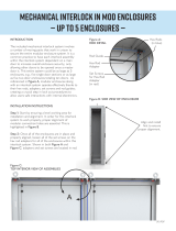
5. Pull the interlock release lever forward. The Interlock release lever is at the
bottom right corner of the door opening.
6. Open the bottom right-hand door by unscrewing the locking bolts.
7. Unbolt and open the bottom left door.
8. Close the doors by reversing the procedure.
Door locking bolts
Door locking bolts
Isolation Switch handle
LV
MV
MV
MV
IMPORTANT
The Bottom MV doors cannot be opened until the interlock release lever is
pulled forward.
IMPORTANT
Verify that the swing-out low voltage panel is in its original position before
attempting to close the medium voltage (MV) door. When closing the MV
doors, verify all door locking-bolts on the right side of the MV door are in place.
Tightened the bolts until the door is even with the flange. Do not over tighten
the bolts. If the door is not securely fastened, the isolation switch handle
cannot be moved to the ON position.

Rockwell Automation Publication 1512A-UM102C-EN-P - November 2015 13
Installation - Standard Enclosure (Not Arc Resistant) Chapter 2
Anchoring
Place the controller in the required installation location. Use M12 (1/2 in.) floor
mounting-bolts to fasten the controller to the mounting surface. See Figure 5
as
an example of the location of the mounting holes in the cabinet.
Figure 5 - Cabinet Floor Plan
ATTENTION: Complete the Power Lockout Procedure on page 45 before
beginning any service procedures to the unit. Failure to do so can result in
severe burns, injury, or death.
IMPORTANT
See the Dimension Drawing for additional details that are related to the
cabinet floor plan.
IMPORTANT
Pre-determined cabinets are designed for Uniform Building Code (UBC) seismic
zone 1, 2A, 2B, 3, 4, and IBC (International Building Code) seismic activity
without overturning or lateral movement. Provided they are securely mounted
according to UBC, IBC, and the local building codes. This restriction can include
concrete pad design, steel floor design and the sizing of cabinet anchors.
Concrete floor cutouts must not be next to floor anchor bolts and must be sized
to seismic load. If an accredited engineer must review the floor mounting,
consult the factory. Many jurisdictions require an engineer from the local area
to review the design. Seismic qualification does not indicate that the
equipment will function properly after a seismic event.
Line Cable Conduit opening.
Load Cable Conduit opening.
Control Wire Conduit opening.
Mounting Holes for M12 (1/2 in.) Diameter Anchor Bolts.
Removable Lifting Angle (2).
1.00 [25] X 3.00 [76] Non- removeable Sill Channels.
Front

14 Rockwell Automation Publication 1512A-UM102C-EN-P - November 2015
Chapter 2 Installation - Standard Enclosure (Not Arc Resistant)
Joining the Sections
1. Position the left side section on a level surface and secure the section in
place with M12 (1/2 in.) Floor mounting-bolts (see Anchoring
on
page 13).
2. When joining NEMA/EEMAC Type 12 sections, apply a continuous
3 mm (0.125 in.) bead of silicon around the perimeter of one section.
3. Remove the side bus access covers, if applicable.
4. Position the right section against the left section. Make sure that the
surface is level.
5. Secure the sections together with 0.25 - 20 self-tapping screws. Thread the
screw through the 0.281 in. clearance hole to the corresponding 0.219 in.
pilot hole. To access the front clearance holes of the left-side cabinet, open
the medium voltage (MV) doors. To access the rear clearance holes,
remove the rear covers of the starter. If rear access is not available, refer to
Front Access – Top Incoming Load Cables
on page 17 or Front Access –
Bottom Incoming Line Cables on page 19.
6. Secure the right section to the floor using ½ in. (M12) floor mounting-
bolts (see Anchoring
on page 13).
IMPORTANT
FOR SEISMIC APPLICATIONS
For installations on concrete – the minimum depth and radius of concrete that
supports the cabinet anchors is dependent on seismic loads. See Anchoring
on
page 13 for important information.
For installations on a metal structure – the metal plate depth and the method
to anchor the cabinet is dependent on seismic loads.
IMPORTANT
The joining hardware can be found in a package mounted to the front of the
shipping skid. See Publication MV-QS050_-EN-P
requirements for a level floor
surface.

Rockwell Automation Publication 1512A-UM102C-EN-P - November 2015 15
Installation - Standard Enclosure (Not Arc Resistant) Chapter 2
Figure 6 - Joining the Sections
Access to the Power Bus
Rear Access
1. Remove the hardware that secures the center rear bus access-cover
(Figure 7
).
2. Remove the center rear bus access-cover.
3. When the rear bus cover is removed, you see the three power bus bars and
grounding bus (Figure 8
).
Side Bus Access Cover
0.281 in. (7.137 mm) Clearance (Qty 3)
0.219 in.(5.562) Pilot Holes (Qty 5)
0.219 in. (5.562)Pilot Holes (Qty 3)
0.281 in. (7.137 mm) Clearance Holes (Qty 5)
ATTENTION: This procedure requires contact with medium voltage (MV)
components. To avoid shock hazards and stop incoming power, do the Power
Lockout Procedure on page 45. Verify that all circuits are voltage free by using a
hot stick or appropriate device that measures voltage. Failure to do so can result
in severe burns, injury, or death.

16 Rockwell Automation Publication 1512A-UM102C-EN-P - November 2015
Chapter 2 Installation - Standard Enclosure (Not Arc Resistant)
Figure 7 - Access to Power Bus From Side and Rear Cabinet, typical
Figure 8 - Bus Bars from Back Access
Side Access
A side bus access cover is on each side of the controller.
1. Remove the hardware from the appropriate side bus access cover.
2. Remove the side bus access cover.
3. When the side bus access cover is removed, you see the three power bus
bars and grounding bus (Figure 9
).
Center Rear Bus Access Cover
Side Bus Access Cover

Rockwell Automation Publication 1512A-UM102C-EN-P - November 2015 17
Installation - Standard Enclosure (Not Arc Resistant) Chapter 2
Figure 9 - Side Bus Access Cover Removed
Front Access – Top Incoming Load Cables
1. Complete the Power Lockout Procedure on page 45 for medium-voltage
power cells and the power bus.
2. Open the low-voltage cell door (see page 11
).
3. Open the medium-voltage cell doors (see page 12
).
4. Remove the self-tapping screws from the low voltage panel if installed.
Installed for shipment purposes – Figure 10
.
Figure 10 - Removal of Access Panel with Low Voltage Panel Rotated.
5. Use a flat head screwdriver to turn the 1/4 turn fasteners counterclockwise
180°.
1/4 turn fasteners
Self-tapping screws

18 Rockwell Automation Publication 1512A-UM102C-EN-P - November 2015
Chapter 2 Installation - Standard Enclosure (Not Arc Resistant)
6. Pull on right-hand side of low voltage panel. Swing the low voltage panel
to the front and left of cabinet (see Figure 12
).
7. Locate the removable bus access barriers.
Figure 11 - Access to Power Bus with Low Voltage Panel Rotated
8. Remove the retaining screws from removable bus access barrier. The
incoming cable connections to main bus are exposed (see Figure 12
).
Figure 12 - Power Bus with Barrier Removed
9. Install the incoming line cables to power bus. Torque to recommended
values on page 10
.
10. Reverse procedure after cables are installed.
IMPORTANT
Before the low voltage panel is rotated, the power cell door must be in a fully
opened position.
The Retaining Screws
Bus Access Barriers
ATTENTION: Make sure that all barriers are installed before re-energizing the
equipment. Failure to do so can result in electrical faults, damage equipment, or
severe injury to personnel.

Rockwell Automation Publication 1512A-UM102C-EN-P - November 2015 19
Installation - Standard Enclosure (Not Arc Resistant) Chapter 2
Front Access – Bottom Incoming Line Cables
If the incoming cables in your cabinet enter the section from the bottom, follow
the same procedure as for Front Access – Top Incoming Load Cables
on page 17.
1. Open all power cell doors.
2. Locate incoming cable duct at rear left-hand side of power cell (see
Figure 13
).
3. Remove self-tapping screws from the cable duct access-barriers. Remove
barriers.
4. Route and install incoming line cables up to power bus. Torque to the
recommended values specified on page 10
.
5. Reverse procedure after cables are installed.
Figure 13 - Access to Bottom Incoming Cables
Load Cable Connections
Bottom cable opening
(top exit cables
configuration shown)
ATTENTION: Make sure that all barriers are installed before re-energizing the
equipment. Failure to do so can result in electrical faults, damage equipment, or
severe injury to personnel.
ATTENTION: To avoid shock hazards and lockout incoming power, do the Power
Lockout Procedure on page 45 before working on the equipment. Verify that all
circuits are voltage free by using a hot stick or appropriate device that measures
voltage. Failure to do so can result in severe burns, injury, or death.
IMPORTANT
The current transformers can be positioned for top or bottom cable exit. Follow
the appropriate procedure that is described for your starter configuration.
IMPORTANT
Cable size cannot exceed 1-1000 MCM, 2-750 MCM, 3-500MCM, or
4-500 MCM per phase.

20 Rockwell Automation Publication 1512A-UM102C-EN-P - November 2015
Chapter 2 Installation - Standard Enclosure (Not Arc Resistant)
1. Complete the Power Lockout Procedure on page 45.
2. Remove the appropriate cable conduit-opening plate from the cabinet (see
Figure 14
…Figure 17). The plate can be punched or cut to mount conduit.
3. Route load cables for the power cell before control cables. Pull the cables
into the cabinet through the appropriate opening (see
Figure 14
…Figure 17).
4. Connect the cables to the current transformers and tighten the
connections to 48 lb•ft (65 N•m).
5. Connect cable shields (if present) to the Ground lug.
6. Reinstall the current transformer barrier and reassemble the cabinet.
Figure 14 - Access to Load Cable Conduit Openings (Top Exit Configuration Shown)
IMPORTANT
See Dimensional Drawings that are provided with order documentation for
additional details that are related to cabinet floor plan.
Current Transformer
Control Cable Conduit Opening
Bottom-exit removable
load cable conduit-plate
/