Page is loading ...

DTP2T212 • Setup Guide
The Extron
DTP2
T
212 is a
two input HDMI switcher with two simultaneous outputs for 4K video signals. The
DTP2
T
212
extends
signals 330feet (100meters) and features two HDMI inputs, one local HDMI output, and one TP output. The TP output extends
digital video and audio, remote power, analog audio, and bidirectional RS-232 and IR. The switcher also features EDIDMinder
®
,
which maintains continuous EDID communication with connected devices and ensures the HDMI sources power up properly and
maintains correct video output, and Key Minder to manage HDCP
®
. The switcher supports computer and video resolutions up
to 2560x1600@60Hz and 4K UHD@60Hz 4:4:4, with a maximum data rate of 18.0Gbps and HDCP2.2. This guide provides
instructions for an experienced installer to set up and operate this switcher.
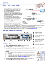
The diagram below shows a typical application for a DTP2T212 switcher.
For full installation, conguration, and operation details,
see the DTP2T212 User Guide, available at www.extron.com.
DTP2 R 212
Switcher DA Extender
OUTPUTS
POWER
12V
0.8A MAX
SIG LINK
DTP2 IN
RS-232
IR
Tx Rx Tx RxG
L R
AUDIO
OVER DTP2
Rx GTx
RS-232 IR
RxTx
OVER TP
POWER
12V
2.0A MAX
RS-232
CONTACT /
TALLY
1
C G T C G GRxTx+VT
2
1
AUDIO
2 A
B
REMOTE
INPUTS
OUTPUTS
SIG LINK
OUT
DTP
HDBT
OFF
SEND
POWER
RS-232
RS-232
HDBT
Video/
Control
MLC Plus 100
MediaLink Plus Controller
Extron
DTP2 T 212
Switcher DA Extender
HDBT
Projector
WiFi
1 2 3 4
Laptop
PC
Local Monitor
HDMI
HDMI
HDMI
RS-232
Control
HDMI
DISPLAY
VOLUME
Extron
ON OFF
PC
VGA
DOC
CAM
MUTE
Figure 1. Application Diagram of the DTP2 T 212
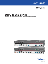
Rear Panel Features and Connections
Rx GTx
RS-232IR
RxTx
OVER TP
POWER
12V
2.0A MAX
RS-232
CONTACT /
TALLY
1
CGTC
GG
RxTx+VT
2
1
AUDIO
2A
B
REMOTE
INPUTS
OUTPUTS
SIG LINK
OUT
DTP
HDBT
OFF
SEND
POWER
J
J
J
JI
I
IH
H
HG
G
G
F
F
F
E
E
ED
D
DC
C
CB
B
BA
A
A
A
Power inlet
F
TP function toggle switch
B
Audio input
G
Over TP RS-232 and IR switching port
C
HDMI input
H
SEND POWER toggle switch
D
HDMI output
I
Contact/Tally port
E
TP2 RJ-45 output
J
Remote RS-232 port
Figure 2. DTP2T212 Rear Panel
Installation Steps
1. Turn off and disconnect all of the equipment from their power sources.
2. Mount the switcher on a rack shelf or furniture (optional).
3. Connect HDMI input sources to one or both of the HDMI inputs (see gure1,
C
).
NOTE: Use provided LockIt lacing brackets to secure the HDMI cables to the ports to reduce stress on the HDMI connectors
and prevent signal loss due to loose cable connections (see LockIt Lacing Brackets on page3).
4. Connect an HDMI device to the HDMI output (
D
). By default, the EDID of this device is stored at the HDMI output.
5. Connect an unbalanced stereo audio source to the 3.5 mm mini stereo input (
B
) for analog audio input (optional). Analog
audio input can be congured to be embedded in the HDMI signal or transmitted separately. It is available for either selected input.
1
2
1

6. Connect an RJ‑45 DTP or HDBT receiving device to the output (see figure2,
E
on the previous
page) for either DTP or HDBT mode (see image to the right to properly wire the RJ-45 connector).
• If the receiver is in the Extron DTP2 series, set the DTP/HDBT toggle switch (
F
) to DTP and the
SEND POWER switch (
H
) to the UP (SEND POWER) position. On the receiver, set the
SEND POWER switch to the DOWN (OFF) position.
• If the receiver is in the Extron Legacy DTP series, set the DTP/HDBT toggle switch (
F
) to
DTP and the SEND POWER switch (
H
) to the DOWN (OFF) position.
• If the receiver is HDBaseT enabled, set the DTP/HDBT toggle switch (
F
) to HDBT, and the
SEND POWER switch (
H
) to the DOWN (OFF) position.
ATTENTION:
• Position these toggle switches (see figure2,
F
and
H
) BEFORE connecting the appropriate device to the TP
connector. Failure to comply can damage the endpoint.
• Positionnez ces sélecteurs (voir figure2,
F
et
H
) AVANT de connecter l’appareil approprié au connecteur TP. Ne pas
respecter cette procédure pourrait endommager le point de connexion.
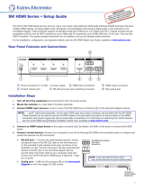
• The DTP2 T 212 is congured to output power to DTP2 models only. If connected to a Legacy DTP or HDBT device, set
the SEND POWER toggle switch to the “DOWN” position (OFF). Failure to turn the power OFF will damage the connected
Legacy DTP device.
• Le DTP2 T 212 est conguré pour fournir une alimentation aux modèles DTP2 uniquement. S’il est connecté à un autre
appareil, veuillez positionner l’interrupteur à bascule sur « DOWN » (OFF). Si l’interrupteur n’est pas positionné sur OFF,
vous risquez d’entraîner la défaillance de l’appareil Legacy DTP connecté.
NOTE: When the output is configured for DTP mode, remote power is available for Extron DTP2 devices only. When the
output is configured for HDBT mode, remote power is disabled and both the switching transmitter and receiver require their
own 12VDC power supply.
DTP2 R 211
CONFIG
INPUT
LINK
OUTPUT
SEND
POWER
OFF
STATUS
SEND
POWER
OFF
SEND
POWER
OFF
DTP2 R 211
CONFIG
INPUT
LINK
OUTPUT
SEND
POWER
OFF
STATUS
SEND
POWER
OFF
SEND
POWER
OFF
SEND
POWER
OFF
DTP HDMI 330 Rx
OVER DTP
RS-232
IR
Tx Rx Tx RxG
OFF
OFF
ON
ON OFF
Rx GTx
RS-232 IR
RxTx
OVER TP
POWER
12V
2.0A MAX
RS-232
CONTACT /
TALLY
1
CGTCGGRxTx+VT
2
1
AUDIO
2A
B
REMOTE
INPUTS
OUTPUTS
SIG LINK
OUT
DTP
HDBT
OFF
SEND
POWER
Rx GTx
RS-232 IR
RxTx
OVER TP
POWER
12V
2.0A MAX
RS-232
CONTACT /
TALLY
1
CGTCGGRxTx+VT
2
1
AUDIO
2A
B
REMOTE
INPUTS
OUTPUTS
SIG LINK
OUT
DTP
HDBT
OFF
SEND
POWER
Rx GTx
RS-232 IR
RxTx
OVER TP
POWER
12V
2.0A MAX
RS-232
CONTACT /
TALLY
1
CGTCGGRxTx+VT
2
1
AUDIO
2A
B
REMOTE
INPUTS
OUTPUTS
SIG LINK
OUT
DTP
HDBT
OFF
SEND
POWER
Local
Power Supply
CATx Cable
up to 330' (100 m)
Local
Power Supply
No Remote Power
Extron
DTP2 T 212
Transmitter
Extron
DTP HDMI 4K 330 Rx
Receiver
DTP Endpoint Connected to a DTP2 Endpoint
CATx Cable
up to 330' (100 m)
Direction of
Remote Power
Local
Power Supply
Extron
DTP2 T 212
Transmitter
Extron
DTP2 R 211
Receiver
CATx Cable
up to 330' (100 m)
Direction of
Remote Power
Extron
DTP2 T 212
Transmitter
Extron
DTP2 R 211
Receiver
DTP2 Endpoint Connected to a DTP2 Endpoint
Local
Power Supply
DTP2 R 211
CONFIG
INPUT
LINK
OUTPUT
SEND
POWER
OFF
STATUS
SEND
POWER
OFF
SEND
POWER
OFF
DTP2 R 211
CONFIG
INPUT
LINK
OUTPUT
SEND
POWER
OFF
STATUS
SEND
POWER
OFF
SEND
POWER
OFF
SEND
POWER
OFF
DTP HDMI 330 Rx
OVER DTP
RS-232
IR
Tx Rx Tx RxG
OFF
OFF
ON
ON OFF
Rx GTx
RS-232 IR
RxTx
OVER TP
POWER
12V
2.0A MAX
RS-232
CONTACT /
TALLY
1
CGTCGGRxTx+VT
2
1
AUDIO
2A
B
REMOTE
INPUTS
OUTPUTS
SIG LINK
OUT
DTP
HDBT
OFF
SEND
POWER
Rx GTx
RS-232 IR
RxTx
OVER TP
POWER
12V
2.0A MAX
RS-232
CONTACT /
TALLY
1
CGTCGGRxTx+VT
2
1
AUDIO
2A
B
REMOTE
INPUTS
OUTPUTS
SIG LINK
OUT
DTP
HDBT
OFF
SEND
POWER
Rx GTx
RS-232 IR
RxTx
OVER TP
POWER
12V
2.0A MAX
RS-232
CONTACT /
TALLY
1
CGTCGGRxTx+VT
2
1
AUDIO
2A
B
REMOTE
INPUTS
OUTPUTS
SIG LINK
OUT
DTP
HDBT
OFF
SEND
POWER
Local
Power Supply
CATx Cable
up to 330' (100 m)
Local
Power Supply
No Remote Power
Extron
DTP2 T 212
Transmitter
Extron
DTP HDMI 4K 330 Rx
Receiver
DTP Endpoint Connected to a DTP2 Endpoint
CATx Cable
up to 330' (100 m)
Direction of
Remote Power
Local
Power Supply
Extron
DTP2 T 212
Transmitter
Extron
DTP2 R 211
Receiver
CATx Cable
up to 330' (100 m)
Direction of
Remote Power
Extron
DTP2 T 212
Transmitter
Extron
DTP2 R 211
Receiver
DTP2 Endpoint Connected to a DTP2 Endpoint
Local
Power Supply
Figure 3. Send Power Toggle Switch Configuration
7. Connect Over TP RS‑232 and IR control. Connect a serial RS-232 signal, a modulated
IR signal, or both into this 3.5
mm, 5-pole captive screw port (
G
) for IR and bidirectional
RS-232 communication (see wiring diagram on the right).
3
5
Pin
1
2
3
6
7
8
4
Wire color
White-green
Green
White-orange
White-blue
Orange
White-brown
Brown
Blue
TIA/EIA T
568B
TP Wires
12345678
Pins:
Rx Tx
Tx Rx
Gnd
Gnd
IR Device
RS-232 Device
OVER TP RS-232/IR
RS-232
OVER TP
IR
Tx Rx Tx RxG
Tx/Rx
Pins
DTP2T212 • Setup Guide (Continued)
2

8. Connect control devices. Connect your computer to one of the following communication ports to congure and control the
switcher via SIS commands or Product Conguration Software (PCS):
• RS‑232 port — Connect the unterminated transmit, receive, and ground wires of the
RS-232 cable to the three pins on the provided 3-pole captive screw connector, as shown
in the diagram on the right. Insert the connector into the rear panel Remote port (
J
), and
the other end of the cable into your computer serial port. Protocol for the RS-232 port:
• 9600 baud • 8 data bits • no parity
• Config port — Connect a USB mini-B cable to the front panel USB port (see figure5,
C
, on the next page) for USB control.
9. Connect a contact closure device (optional). Connect a push-button contact closure device to a
Contact port (see figure2,
I
, on page1) to enable input switching via contact closure.
a. Wire and plug one of the provided blue, 3.5mm, 3-pole connectors into a Contact/Tally port
representing input 1 or input 2 on the DTP2T212.
• C = Contact closure input
• G = Contact and Tally Ground
• T = Tally output
b. Press the button on the contact closure device to switch the connected input to the output.
TIP: The Contact and Tally ports can be used with Extron Show Me cables. For each cable, connect
the red wire to the Contact Closure pin and the black wire to the Tally Out pin (see diagram on the
right).
10. Connect an indicator device to the Tally Out port (optional). To identify the currently selected input when the front panel
buttons are not visible, connect a device such as an LED to the Contact/Tally port (figure2,
I
). When the input you are using is
selected, the corresponding tally out pin shorts to ground, which activates the connected indicator.
Wire and connect one of the provided blue, 3.5
mm, 4-pole connectors into a Contact In/Tally Out port.
• C = Contact closure input
• G = Contact and Tally Ground
• T = Tally output
• +V = +5 VDC (Insert the power wire for the contact indicator device into the +V port.)
CONTACT /
TALLY
1
C
G
T
CG +VT
2
11. If necessary, wire a 2-pole captive screw connector to your power supply as shown in gure4 (see figure2,
A
on page1).
SECTION A–A
Ridges
Smooth
A
A
3/16"
(5 mm) Max.
POWER
12V
--A MAX
Figure 4. Wiring the Power Connector
CAUTION: The DC output cables must be kept separate from each
other while the power supply is plugged in. Remove power before
wiring.
ATTENTION : Les câbles de sortie CC doivent être séparés les uns
des autres tant que la source d’alimentation est branchée. Coupez
l’alimentation avant d’effectuer un raccordement.
ATTENTION:
• Do not connect any external power supplies until you have read the Attention notications in the Power Supply section of
the DTP2 T/R 211 User Guide.
• Ne branchez pas de sources d’alimentation externes avant d’avoir lu les mises en garde dans la section « Power Supply »
du DTP2 T/R 211 User Guide.
12. Power on the output display.
13. Connect power to the switcher.
14. Power on the source devices.
LockIt Lacing Brackets
Use the included LockIt Lacing Brackets to securely fasten the HDMI cables to each device as follows.
1
Plug the HDMI cable into the rear panel connection.
2
Loosen the HDMI connection mounting screw from the panel enough to allow the LockIt lacing
bracket to be placed over it. The screw does not have to be removed.
3
Place the LockIt lacing bracket on the screw and against the HDMI connector, then tighten the screw
to secure the bracket.
4
CONTACT /
TALLY
1
CGT
Red
Black
Show Me Cable
CG +VT
2
1
3
4
2
5
REMOTE RS-232
Tx Rx
RS-232
G
REMOTE
3

DTP2T212 • Setup Guide (Continued)
For information on safety guidelines, regulatory compliances, EMI/EMF compatibility, accessibility, and related topics, see the
Extron Safety and Regulatory Compliance Guide on the Extron website.
© 2019 Extron Electronics — All rights reserved. www.extron.com
All trademarks mentioned are the property of their respective owners.
Worldwide Headquarters: Extron USA West, 1025 E. Ball Road, Anaheim, CA 92805, 800.633.9876
ATTENTION:
• Do not overtighten the HDMI connector mounting screw. The shield it fastens to is very thin and can easily be stripped.
• Ne serrez pas trop la vis de montage du connecteur HDMI. Le blindage auquel elle est attachée est très n et peut
facilement être dénudé.
4
Loosely place the included tie wrap around the HDMI connector and the LockIt lacing bracket as shown.
5
While holding the connector securely against the lacing bracket, use pliers or similar tools to tighten the tie wrap, then remove any
excess length.
Front Panel Features
DTP2 T 212
CONFIG
2
AB
1
INPUTS
MODE NORM/AUTO
OUTPUTS
SIGNAL
HDCP
R
AUTO
SWITCH
INPUTS
1
2
A
A
A B
B
B C
C
C D
D
D E
E
E
F
F
F
A
Auto Switch LED
C
USB Config port
E
Inputs and Outputs Signal LEDs
B
Reset Button
D
Input selection buttons and LEDs
F
Inputs and Outputs HDCP LEDs
Figure 5. DTP2T212 Front Panel
A
Auto Switch LED — Lights when Auto Switch is enabled.
B
Reset button — Press and hold the reset button for 3 seconds while operating the unit to reset back to factory default.
C
USB Config port — Connect a USB A to mini-B cable between your computer and this female USB mini-B port to configure and
control the switcher via SIS commands or PCS, and to update the firmware.
D
Inputs selection buttons and LEDs — Press one of these buttons to select an input to switch to the output. The LED at the right of
each button lights when the corresponding input is selected. If auto-input switching is in effect, these buttons are disabled, but the
LEDs continue to light to indicate the selected input.
To enable or disable Auto-Switch mode via the front panel, press and hold the Input
1 button for 3 seconds, then press and
release the Input
2 button to toggle between Normal and Auto Switch.
E
Inputs and Outputs LEDs
• Inputs — Light when a source is connected to the corresponding input and TMDS clock activity is detected.
• Outputs — Light when active sink devices are connected to the HDMI and TP outputs.
F
Inputs and Outputs HDCP LEDs
• Inputs — Light if the connected sources are HDCP encrypted and have been authenticated by the switcher inputs.
NOTE: If the source device connected to the selected input is HDCP encrypted (requires HDCP authentication), the
corresponding signal LED may not light unless HDCP has been authenticated.
• Outputs — Light when the currently selected input requires HDCP and the connected output device has been successfully
authenticated.
NOTE: HDCP is re-authenticated on the output whenever a new input is selected.
NOTE: All front panel LEDs will flash three times simultaneously to indicate enabling or disabling of Executive Mode, which will lock
out front panel input buttons when enabled via PCS or SIS commands.
5
68-2915-50 Rev. A
12 19
4
/