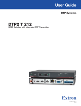
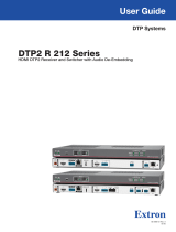
Extron DTP2 R 211 User manual

Type
User manual

This manual is also suitable for

User Guide
DTP2T/R211
DTP Systems
HDMI Twisted Pair Transmitters and Receivers
68‑2938‑01 Rev. H
08 23
Safety Instructions
Safety Instructions • English
WARNING: This symbol, , when used on the product, is intended to
alert the user of the presence of uninsulated dangerous voltage within
the product’s enclosure that may present a risk of electric shock.
ATTENTION: This symbol, , when used on the product, is intended
to alert the user of important operating and maintenance (servicing)
instructions in the literature provided with the equipment.
For information on safety guidelines, regulatory compliances, EMI/EMF
compatibility, accessibility, and related topics, see the Extron Safety and
Regulatory Compliance Guide, part number 68‑290‑01, on the Extron website,
www.extron.com.
www.extron.com.
.
.
I
www.extron.com.
www.extron.com.
.
Copyright
© 2019‑2023 Extron. All rights reserved. www.extron.com
Trademarks
All trademarks mentioned in this guide are the properties of their respective owners.
The following registered trademarks (®), registered service marks (SM), and trademarks (TM) are the property of RGBSystems, Inc. or Extron (see the
current list of trademarks on the Terms of Use page at www.extron.com):
Registered Trademarks (®)
Extron, Cable Cubby, ControlScript, CrossPoint, DTP, eBUS, EDID Manager, EDID Minder, eLink, Flat Field, FlexOS, Glitch Free, GlobalConfigurator,
GlobalScripter, GlobalViewer, Hideaway, HyperLane, IPIntercom, IPLink, KeyMinder, LinkLicense, LockIt, MediaLink, MediaPort, NAV,
NetPA, PlenumVault, PoleVault, PowerCage, PURE3, Quantum, ShareLink, Show Me, SoundField, SpeedMount, SpeedSwitch, StudioStation,
SystemINTEGRATOR, TeamWork, TouchLink, V‑Lock, VN‑Matrix, VoiceLift, WallVault, WindoWall, XPA, XTP, XTPSystems, and ZipClip
Registered Service Mark(SM) : S3 Service Support Solutions
Trademarks ()
AAP, AFL (Accu‑RATEFrameLock), ADSP(Advanced Digital Sync Processing), AVEdge, CableCover, CDRS(ClassD Ripple Suppression),
CodecConnect, DDSP(Digital Display Sync Processing), DMI (DynamicMotionInterpolation), DriverConfigurator, DSPConfigurator, DSVP(Digital
Sync Validation Processing), EQIP, Everlast, FastBite, Flex55, FOX, FOXBOX, IP Intercom HelpDesk, MAAP, MicroDigital, Opti‑Torque,
PendantConnect, ProDSP, QS‑FPC(QuickSwitch Front Panel Controller), RoomAgent, Scope‑Trigger, SIS, SimpleInstructionSet, Skew‑Free,
SpeedNav, Triple‑Action Switching, True4K, True8K, Vector™ 4K, WebShare, XTRA, and ZipCaddy
FCC Class A Notice
This equipment has been tested and found to comply with the limits for a Class A digital
device, pursuant to part15 of the FCC rules. The ClassA limits provide reasonable
protection against harmful interference when the equipment is operated in a commercial
environment. This equipment generates, uses, and can radiate radio frequency energy and,
if not installed and used in accordance with the instruction manual, may cause harmful
interference to radio communications. Operation of this equipment in a residential area is
likely to cause interference; correcting the interference is at the expense of the user.
ATTENTION:
The Twisted Pair Extension technology works with unshielded twisted pair (UTP)
or shielded twisted pair (STP) cables; but to ensure FCC Class A and CE
compliance, STP cables and STP Connectors are required.
La technologie extension paires torsadées fonctionne avec les câbles paires
torsadées blindées(UTP) ou non blindées(STP). Afin de s’assurer de la
compatibilité entre FCC ClasseA et CE, les câbles STP et les connecteurs STP
sont nécessaires.
NOTES:
This unit was tested with shielded I/O cables on the peripheral devices. Shielded
cables must be used to ensure compliance with FCC emissions limits.
For more information on safety guidelines, regulatory compliances, EMI/EMF
compatibility, accessibility, and related topics, see the Extron Safety and
Regulatory Compliance Guide on the Extron website.
Conventions Used in this Guide
Notifications
The following notifications are used in this guide:
CAUTION: Risk of minor personal injury.
ATTENTION : Risque de blessuremineure.
ATTENTION:
Risk of property damage.
Risque de dommages matériels.
NOTE: A note draws attention to important information.
Software Commands
Commands are written in the fonts shown here:
^AR Merge Scene,,Op1 scene 1,1 ^B 51 ^W^C
[01] R 0004 00300 00400 00800 00600 [02] 35 [17] [03]
E X! *X1&* X2)* X2#* X2! CE}
NOTE: For commands and examples of computer or device responses mentioned
in this guide, the character "0" is used for the number zero and "O" is the capital
letter "o."
Computer responses and directory paths that do not have variables are written in the font
shown here:
Reply from 208.132.180.48: bytes=32 times=2ms TTL=32
C:\Program Files\Extron
Variables are written in italics form as shown here:
ping xxx.xxx.xxx.xxx —t
SOH R Data STX Command ETB ETX
Selectable items, such as menu names, menu options, buttons, tabs, and field names are
written in the font shown here:
From the File menu, select New.
Click the OK button.
Specifications Availability
Product specifications are available on the Extron website, www.extron.com.
Extron Glossary of Terms
A glossary of terms is available at https://www.extron.com/technology/glossary.aspx.
viiDTP2 T/R 211 • Table of Contents
Contents
Introduction ................................................1
About this Guide .................................................. 1
About the DTP2211 Transmitter and Receiver .... 1
Control Communications ................................. 2
TP Cable Advantages ...................................... 2
Application Diagram ............................................ 2
Features .............................................................. 3
Installation and Operation............................ 5
Installation Overview ............................................ 5
Connections ........................................................ 6
Transmitter Rear Panel Connections ................ 6
Receiver Rear Panel Connections .................... 8
Securing the HDMI Connector ....................... 10
TP Cable Termination and
Recommendations ....................................... 11
Power Supply Wiring ..................................... 12
RS‑232 and IR Connector Wiring .................. 14
Operations......................................................... 15
Front Panel Features ...................................... 15
Connecting to the Front Panel USB Port ........ 17
Resetting ....................................................... 17
Analog Audio Embedding (Transmitter) .......... 17
HDMI Audio De‑embedding (Receiver) ........... 17
Remote Control .........................................18
Introduction to SIS ............................................. 18
Error Messages ............................................. 18
Timeout ......................................................... 18
Symbols Used in this Guide ............................... 19
Symbol Definitions ......................................... 19
Command and Response Table for
SIS Commands ................................................ 20
Downloading and Updating Firmware ................ 22
Downloading Extron Firmware Loader ........... 22
Installing Firmware Loader ............................. 23
Downloading Firmware to a PC ..................... 23
Updating Firmware on a DTP2211 Device .... 24
Reference Information ...............................28
Mounting the Transmitter or Receiver ................. 28
Tabletop Mounting ......................................... 28
Mounting Kits ................................................ 28
UL Rack‑Mounting Guidelines ....................... 29
Internal Settings ................................................. 30
Extron Warranty ........................................ 33
FCC Class A Notice .............................................iv
Conventions Used in this Guide ............................v
Notifications ..................................................... v
Software Commands ........................................v
Specifications Availability ......................................v
Extron Glossary of Terms ......................................v
DTP2 T/R 211 • Table of Contents viii
DTP2 T/R 211 • Introduction 1
Introduction
About this Guide
About the DTP2211 Transmitter and Receiver
Application Diagram
Features
About this Guide
This guide describes the Extron DTP2211 long distance High Definition Multimedia Interface
(HDMI) Twisted Pair Extenders, which consists of a transmitter and receiver:
DTP2T211 — 330feet (100meters) transmitter
DTP2R211 — 330feet (100meters) receiver
This guide describes how to install, operate, and configure the transmitter and receiver.
About the DTP2211 Transmitter and Receiver
The Extron DTP2211 transmitter and receiver pair (see figure1 on page2) extends
the usable distance of HDMI digital video with resolutions up to 4K@60Hz (4:4:4), analog
audio, remote power, and bidirectional RS‑232 and infrared (IR) control signals over one
Extron XTPDTP24 shielded twisted pair (STP) cable (recommended), or Category CAT 6a,
or CAT 7 STP, or unshielded twisted pair (UTP) cable up to 330feet (100meters).
The DTP2211 devices extend the digital signal to Legacy DTP inputs 330feet
(100meters) with a maximum resolution of up to 4K @ 30Hz, 4:4:4, supporting data rates
up to 10.2Gbps.
The DTP2211 devices extend the digital signal to DTP2 inputs 330feet (100meters)
with a maximum resolution of up to 4K @ 60Hz, 4:4:4, supporting data rates up to
18Gbps.
Both units are HDMI(2.0b and 1.4) and HDCP(2.3 and 1.x) compliant. EDID and CEC
are negotiated from source to sink, with the transmitter and receiver transparent during
the exchange. The transmitter input always reports to the source as an HDCP‑authorized
device, so signal from devices such as Apple products are always encrypted. This cannot
be disabled.
DTP2 transmitters feature configurable analog audio embedding that can be configured
via Simple Instructions Set (SIS) commands.
DTP2 receivers feature configurable digital audio de‑embedding, which can be selected
using the audio toggle switch on the rear panel.
The DTP2211 transmitter and receiver are housed in 1 inch tall, quarter rack width,
6inches deep metal enclosures. They can be set on a tabletop, mounted in a rack, or under
or through furniture. The receiver can also be mounted on a projector bracket.
DTP2 T/R 211 • Introduction 2
Control Communications
The RS‑232 and IR communications are passive pass‑through only. The transmitter and
receiver do not generate or respond to the RS‑232 and IR communication signals. EDID
and CEC are negotiated from source to sink, with the transmitter and receiver transparent
during the exchange. The transmitter input always reports to the source as an HDCP‑
authorized device, so signals from devices such as Apple products are always encrypted.
This cannot be disabled.
TP Cable Advantages
Twisted pair cable is much smaller, lighter, more flexible, and less expensive than coaxial
or HDMI cable. These transmitter and receiver twisted pair (TP) products make cable runs
simpler and less cumbersome. Termination of the cable with RJ‑45 connectors is simple,
quick, and economical.
ATTENTION:
Do not use Extron UTP23SF‑4 Enhanced Skew‑Free AV UTP cable or STP201
cable to link the transmitter and receiver. The DTP2211 T/R do not work
properly with these cables.
N’utilisez pas le câble audiovisuel Skew Free UTP version améliorée UTP23SF‑4
Extron ou le câble STP201 pour relier l’émetteur et le récepteur/sélecteur. Le
DTP2211 T/R ne fonctionne pas correctement avec ces câbles.
Application Diagram
INPUT
OFF
SEND
POWER
STATUS
OUTPUT
LINK
DTP2 R 211
CONFIG
L
RS-232 IR
Tx Rx Tx RxG
R
POWER
12V
--A MAX
AUDIO
OUTPUTS
OVER DTP2
SIG LINK
DTP2 IN
POWER
12V
--A MAX AUDIO
INPUTS SIG LINK
DTP2 OUT
OVER DTP2
RS-232IR
Tx Rx Tx RxG
INPUT
OFF
SEND
POWER
STATUS
OUTPUT
LINK
DTP2 T 211
CONFIG
POWER
12V
0.3A MAX
IPL PRO S3
G
Tx Rx RTS CTS G
Tx Rx RTS CTS G
Tx Rx RTS CTS
COM 1 COM 2 COM 3
LAN / PoE
4K/60 Display
CATx Cable up to 330' (100 m)
RS-232
RS-232
HDMIHDMIAudio
PC with 4K/60 Video Output
Extron
DTP2 T 211
Transmitter
Extron
IPL Pro S3
IP Link Pro
Control Processor
Extron
DTP2 R 211
Receiver
Figure 1. Typical DTP2 211 Transmitter and Receiver Application
1
DTP2 T/R 211 • Introduction 3
Features
Transmits HDMI plus control and analog audio up to 330 feet (100 meters) over
a shielded CATx cable — The DTP2T211 provides high reliability and maximum
performance on an economical and easily installed cable infrastructure.
Receives HDMI plus control and analog audio up to 330 feet (100 meters) over
a shielded CATx cable — The DTP2R211 provides high reliability and maximum
performance on an economical and easily installed cable infrastructure.
DTP2 R 211 inputs and output
Input: One DTP2 twisted pair input on RJ‑45
Outputs: One HDMI, stereo audio on captive screw
DTP2 T 211 inputs and output
Inputs: One HDMI, one 3.5 mm stereo mini jack for audio
Output: One DTP2 twisted pair input on RJ 45
Supports computer and video resolutions up to 4K/60 @ 4:4:4 — Support of
4K/60 at 4:4:4 chroma sampling requires connection to a matching DTP2 product.
Stereo audio de-embedding (DTP2 R 211) — The captive screw stereo output is
selectable for de embedded or pass‑through analog audio.
Analog stereo audio embedding (DTP2 T 211) — Analog stereo audio signals can
be selectively embedded onto the digital video output signal and transported over DTP.
The DTP2 T 211 can be set to pass the embedded digital audio, embed the analog
audio, or to automatically embed the analog audio when no digital audio is detected.
Accepts additional analog stereo audio signals — The DTP2 R 211 accepts stereo
analog audio from a DTP enabled product. The DTP2 T 211 accepts stereo analog
audio signals for simultaneous transmission over the same shielded twisted pair cable.
Supported HDMI 2.0 specification features include data rates up to 18 Gbps,
3D, HD lossless audio formats, and CEC pass-through
HDCP 2.3 compliant — Ensures display of content‑protected 4K video media and
maintains interoperability with earlier versions of HDCP.
Remote power capability — For simplified installation, the transmitter can be remotely
powered by a DTP2‑enabled product over the twisted pair connection. It can also be
configured to provide power to the connected DTP2 receiver product.
Supports Consumer Electronics Control (CEC) signal transmission — CEC
control passes through from the transmitter to the receiver.
Bidirectional RS 232 and IR pass-through for AV device control — Bidirectional
RS 232 control and IR signals can be transmitted alongside the video signal, allowing
remote AV devices to be controlled without the need for additional cabling.
Supports multiple embedded audio formats — Compatible with a broad range of
multi‑channel audio signals, providing reliable operation with HDMI sources.
Front panel USB configuration port — Provides convenient access for information
and firmware updates.
LED indicators for signal presence, power, and link status — Provide visual
indication of system status for real‑time feedback and monitoring of key performance
parameters.
RJ 45 signal and link LED indicators for DTP port — Provide a means for validating
signal flow and operation, allowing quick identification of connectivity issues
DTP2 T/R 211 • Introduction 4
1-inch high, quarter rack width, metal enclosures — With low profile enclosures,
the transmitter and receiver can be discreetly installed in locations such as behind a
plasma or LCD flat‑panel display.
Includes LockIt HDMI cable lacing brackets — LockIt lacing brackets are used to
secure HDMI cables connected to the HDMI input and output connectors, preventing
accidental disconnection of the cables.
Extron XTP DTP 24 shielded twisted pair cable is strongly recommended for
optimal performance.
Compatible with CATx shielded twisted pair cable — The DTP2R211 and
DTP2T211 fully support a maximum transmission distance of 330 feet (100 meters)
for all compatible resolutions when used with CATx shielded twisted pair cable.
Shielded twisted pair cabling with solid center conductor sizes of 24AWG or better is
recommended for optimal performance.
External Extron Everlast power supply included (with the transmitter only)
Provides worldwide power compatibility with high‑demonstrated reliability and low
power consumption.
Extron Everlast Power Supply is covered by a 7-year parts and labor warranty.
DTP2 T/R 211 • Installation and Operation 5
Installation and Operation
This section describes the installation and the operation of the DTP2211 transmitter and
receiver, including:
Installation Overview
Connections
Operations
Installation Overview
To install and set up the DTP2211 transmitter and receiver:
1. Turn off all equipment and disconnect it from the power source.
2. Mount the transmitter and receiver (optional) on a rack shelf or furniture (see
Mounting the Transmitter or Receiver on page28).
3. Connect an HDMI input source to the DTP2T211 input (see figure2, C on
page6).
4. Connect an HDMI output device to the DTP2R211 HDMI output (see figure3, D
page8).
NOTE: LockIt cable lacing brackets are provided to secure the HDMI cables to the
port to reduce stress on the HDMI connectors and prevent signal loss due to
loose cable connections (see Securing the HDMI Connector on page10).
5. Connect the transmitter DTP2 Out RJ-45 port (see figure2, D) to the receiver
DTP2 In RJ‑45 port (see figure3, C) using a Twisted Pair Cable.
6. Connect an unbalanced stereo audio source to the 3.5 mm mini stereo input on
the DTP2T211 (see figure2, B) for an analog audio input.
7. Connect a balanced or unbalanced stereo or mono audio device to the
DTP2R211 via the Audio captive screw output (see figure3, F).
8. Set the Audio configuration toggle switch (see figure3, E) on the DTP2R211
to the UP position to de‑embed digital audio from the HDMI signal and output it to the
captive screw output for analog audio output. Set the Audio configuration toggle
switch to the DOWN position for the analog input from the TRS audio port on the Tx unit
to be transported simultaneously with the digital embedded HDMI audio and output on
the captive screw output (see figure3, F).
9. Connect a serial RS-232 signal, a modulated IR signal, or both into this 3.5mm,
5‑pole captive screw Over DTP port for bidirectional RS‑232 and IR communication
(see figure2, E on the transmitter and figure3, B on the receiver).
10. Connect control devices. Connect your computer to the front panel Configuration
port (see figure9, B on page15 on the transmitter and receiver) to configure and
control the transmitter and receiver via SIS commands.
11. Power on the output display.
DTP2 T/R 211 • Installation and Operation 6
12. In a DTP2 transmitter to DTP2 receiver configuration, set the SEND POWER
toggle switch to the UP position on the powered DTP2 device to enable sending
remote power to the far end DTP2 device. Set the toggle switch to the DOWN position on
the DTP2 device receiving power (see figure9, D on page15).
ATTENTION:
The DTP2211 device is configured to output power to DTP2 models only. If
connected to a Legacy DTP device, set the toggle switch to the DOWN (OFF)
position. Failure to turn the power OFF will damage the connected Legacy
DTP device.
Le DTP2211 est configuré pour fournir une alimentation aux modèles
DTP2 uniquement. S’il est connecté à un autre appareil, veuillez positionner
l’interrupteur à bascule sur « DOWN » (OFF). Si l’interrupteur n’est pas
positionné sur OFF, vous risquez d’entraîner la défaillance de l’appareil
Legacy DTP connecté.
13. Connect power to the transmitter or receiver.
14. Power on the source devices.
After the transmitter, the receiver, and their connected devices are powered up, the system
is fully operational. If any problems are encountered, ensure all cables are routed and
connected properly.
NOTE: Ensure the video source and display selected for the DDC are properly
connected to the transmitter and receiver pair, and the transmitter, receiver, and
display have power applied before power is applied to the video source. If the other
devices are not turned on before the video source, the image may not appear.
Connections
Transmitter Rear Panel Connections
INPUTS
POWER
12V
0.8A MAX
SIG LINK
DTP2 OUT
OVER DTP2
RS-232 IR
Tx Rx Tx RxG
AUDIO
A
A
AB
B
BC
C
CD
D
DE
E
E
A Power inlet
B Audio input
C HDMI input
D DTP2 Output RJ-45 port
E Over DTP2 RS-232 and IR port
Figure 2. DTP2T211 Transmitter Connectors
A Power inlet — Plug the included external 12VDC power supply into either this 2‑pole
inlet or the power inlet on the receiver (see figure3, A on page8, and Power
Supply Wiring on page12 to wire the connector).
2
DTP2 T/R 211 • Installation and Operation 7
NOTES:
One power supply is included with the transmitter and can normally power
both units. Remote power is only available if both the transmitter and the
receiver are from the ExtronDTP2 series.
The power supply can be plugged into either the transmitter or the receiver
to power both units.
If the internal jumper setting for ground is removed, a DTP2 211 unit cannot
remotely power the other unit, because of ground potential differences. Each
unit requires a local power supply (see Internal Settings on page30).
B Audio input (Optional)— (see figure2 on page6) Plug an analog audio input
into the transmitter via this female 3.5mm TRS stereo connector (see Analog Audio
Embedding (Transmitter) on page17).
NOTE: The analog audio input is in addition to
the digital audio that may be embedded in the
HDMI input (see the figure at right to identify the
connector tip, ring, and sleeve).
A mono audio connector consists of the tip
and sleeve.
A stereo audio connector consists of the tip,
ring, and sleeve.
Sleeve ( )
Ring (
-
)
Tip (+)
3.5 mm Stereo Plug Connector
(balanced)
C HDMI input — Connect an HDMI cable between this port and the HDMI output port (or
DVI port, with an appropriate adapter) of the digital video source.
NOTE: See Securing the HDMI Connector on page10 to securely fasten the
HDMI connector to the transmitter and the receiver.
D DTP2 Out RJ-45 port — Connect one end of a TP cable to this RJ‑45 port on the
transmitter. Ensure the opposite end of this cable is connected to the receiver DTP2
Input RJ‑45 port (see figure3, C on page8).
Signal LED — This green LED indicates the unit is receiving a TMDS clock signal
on the HDMI input.
Link LED — This amber LED indicates a valid link is established between the units
on the DTP input and output cable.
ATTENTION:
Do not connect these devices to a telecommunications or computer data
network.
Ne connectez pas ces appareils à un réseau de télécommunications ou de
données informatiques.
NOTE: See TP Cable Termination and Recommendations on page11 to
properly wire the RJ‑45 connectors and detailed NOTES on page9.
E Over DTP2 RS-232 and IR port — Connect a serial RS‑232 signal, a modulated IR
signal, or both to this 3.5mm, 5‑pole captive screw port for bidirectional RS‑232 and
IR communication (see RS-232 and IR Connector Wiring on page14 to wire the
connector).
DTP2 T/R 211 • Installation and Operation 8
Receiver Rear Panel Connections
OUTPUTS
POWER
12V
0.8A MAX
SIG LINK
DTP2 IN
RS-232 IR
Tx Rx Tx RxG
LR
AUDIO
OVER DTP2
A
A
AB
B
BC
C
CD
D
DE
E
EF
F
F
A Power inlet
B Over DTP2 RS-232 and IR port
C DTP2 IN RJ-45 port
D HDMI output
E Audio configuration toggle switch
F Audio output
Figure 3. DTP2211 Receiver Connectors
A Power inlet — Plug the included external 12VDC power supply into either this 2‑pole
inlet or the power inlet on the transmitter (see figure2,A on page6, and Power
Supply Wiring on page12 to wire the connector).
NOTES:
One power supply is included with the transmitter and can normally power
both units. Remote power is only available if both the transmitter and the
receiver are from the ExtronDTP2 series.
The power supply can be plugged into either the transmitter or the receiver
to power both units.
If the internal jumper setting for ground is removed, a DTP2 211 unit cannot
remotely power the other unit, because of ground potential differences. Each
unit requires a local power supply (see Internal Settings on page30)
B Over DTP2 RS-232 and IR port — Connect a serial RS‑232 signal, a modulated IR
signal, or both to this 3.5mm, 5‑pole captive screw port for bidirectional RS‑232 and
IR communication (see RS-232 and IR Connector Wiring on page14 to wire the
connector).
C DTP2 In RJ-45 port — Connect one end of the TP cable from the transmitter output
to this RJ‑45 port. Ensure the opposite end of this cable is connected to the transmitter
DTP2 Output RJ‑45 port (see figure2, D on page6).
Signal LED — This green LED indicates the unit is receiving a valid signal on the
DTP In port.
Link LED — This amber LED indicates a valid link is established between the units
on the DTP input and output cable.
NOTE: See TP Cable Termination and Recommendations on page11 to
properly wire the RJ‑45 connectors and detailed NOTES on page11.
D HDMI output — Connect a display with an HDMI input port (or DVI input port, with an
appropriate adapter) to display the transmitted digital image.
NOTE: See Securing the HDMI Connector on page10 to securely fasten the
HDMI connector to the transmitter and the receiver.
E Audio configuration toggle switch
Set the toggle switch to the UP position to de‑embed digital audio from the HDMI
signal and output it to the captive screw output for analog audio output.
Set the toggle switch to the DOWN position for the analog input from the TRS audio
port on the Tx unit to be transported simultaneously with the digital embedded
HDMI audio and output on the captive screw output (see figure3, E and HDMI
Audio De-embedding (Receiver) on page17).
3
DTP2 T/R 211 • Installation and Operation 9
F Audio output — This 5‑pole, 3.5mm captive screw connector outputs the transmitted,
unamplified, line level analog audio. Connect a balanced or unbalanced stereo or
mono audio device, such as an audio amplifier or powered speakers (see figure3 on
page8).
See figure4 to properly wire a captive screw output connector. Use the supplied
tie‑wrap to strap the audio cable to the extended tail of the connector.
Balanced Audio Output
Tip
Ring
Tip
Ring
Sleeves
Unbalanced Audio Output
Tip
Tip
Sleeves
LR
LR
Do not tin the wires!
No Ground Here
No Ground Here
Figure 4. Captive Screw Connector Wiring for Stereo Audio Output
NOTE: See the Attention notifications before wiring the captive screw connector.
ATTENTION:
For unbalanced audio, connect the sleeves to the ground contact. DO NOT
connect the sleeves to the negative (–) contacts.
Pour l’audio asymétrique, connectez les manchons au contact au sol. Ne
PAS connecter les manchons aux contacts négatifs (–).
Do not tin the wire leads before installing into the connector. Tinned wires
are not as secure in the connector and could be pulled out.
Ne pas étamer les conducteurs avant de les insérer dans le connecteur. Les
câbles étamés ne sont pas aussi bien fixés dans le connecteur et pourraient
être tirés.
The length of the exposed wires in the stripping process is important. The
ideal length is 3/16inch (5mm). Any longer and the exposed wires may
touch, causing a short circuit between them. Any shorter and the wires can
be easily pulled out even if tightly fastened by the captive screws.
La longueur des câbles exposés est importante lorsque l’on entreprend de
les dénuder. La longueur idéale est de 5mm (3/16inches). S’ils sont
trop longs, les câbles exposés pourraient se toucher et provoquer un court‑
circuit. S’ils sont trop courts, ils peuvent être tirés facilement, même s’ils
sont correctement serrés par les borniers à vis.
4
DTP2 T/R 211 • Installation and Operation 10
Securing the HDMI Connector
HDMI signals run at a very high frequency and are especially prone to errors caused by bad
video connections, too many adapters, or excessive cable length. To avoid the loss of an
image or jitter, follow these guidelines:
Limit or avoid the use of adapters.
Use only cables specifically intended for HDMI or DVI signals.
To securely fasten an HDMI cable to a device:
1. Plug the HDMI cable into the rear panel connection (see figure2 on page6 and
figure3 on page8).
3
33
11
44
55
22
Figure 5. Installing the LockItTM Lacing Bracket
2. Loosen the HDMI connection mounting screw from the panel enough to allow the
LockIt lacing bracket to be placed over it (2). The screw does not have to be removed.
3. Place the LockIt lacing bracket on the screw and against the HDMI connector, then
tighten the screw to secure the bracket (3).
ATTENTION:
Do not overtighten the HDMI connector mounting screw. The shield to
which it fastens is very thin and can easily be stripped.
Ne serrez pas trop la vis de montage du connecteur HDMI. Le blindage
auquel elle est attachée est très fin et peut facilement être dénudé.
4. Loosely place the included tie wrap around the HDMI connector and the LockIt lacing
bracket (4).
5. While holding the connector securely against the lacing bracket, use pliers or similar
tools to tighten the tie wrap, then remove any excess length (5).
5
DTP2 T/R 211 • Installation and Operation 11
TP Cable Termination and Recommendations
The TIA/EIA T 568B wiring standard is detailed in figure6. Use this standard to terminate
TP cables with RJ‑45 connectors.
5
Pin
1
2
3
6
7
8
4
Side
12345678
Insert
Tw isted
Pair Wires
Pins:
RJ-45
Connecto
r
Wire color
White-green
Green
White-orange
White-blue
Orange
White-brown
Brown
Blue
TIA/EIA T
568 B
Figure 6. TP Cable Termination
ATTENTION:
Do not use Extron UTP23SF‑4 Enhanced Skew‑Free AV UTP cable or STP201
cable to link the XTP products or with DTP2 transmitters or receivers. The
DTP2211 does not work properly with these cables.
N’utilisez pas le câble audiovisuel Skew‑Free UTP version améliorée UTP23SF‑4
Extron ou le câble STP201 pour relier les produits XTP à des émetteurs ou
récepteurs DTP2. Le DTP2 211 ne fonctionne pas correctement avec ces
câbles.
Supported cables —
The DTP2211 transmitter and receiver are compatible with CAT 6a, and CAT 7 shielded
twisted pair (F/UTP, SF/UTP, and S/FTP) and unshielded twisted pair (U/UTP) cable.
Cable recommendations —
Extron recommends using the following practices to achieve full transmission distances up
to 330feet (100meters) and reduce transmission errors.
Use the following Extron XTPDTP24SF/UTP cables and DTP 24 connectors for the
best performance:
XTPDTP24/1000 Non‑Plenum 1000feet (305meters) spool
XTPDTP24P/1000 Plenum 1000feet (305meters) spool
XTPDTP24 Plug Package of 10
If not using XTPDTP24 cable, at a minimum, Extron recommends 24AWG, solid
conductor, STP cable with a minimum bandwidth of 400MHz.
Terminate cables with shielded connectors to the TIA/EIAT568B standard.
Use no more than two pass‑through points, which may include patch points, punch
down connectors, couplers, and power injectors. If these pass‑through points are
required, use CAT6 or 6a shielded couplers and punch down connectors.
NOTES: When using CAT 6a and CAT 7 cable in bundles or conduits, consider this:
Do not exceed 40% fill capacity in conduits.
Do not comb the cable for the first 65feet (20meters), where cables are
straightened, aligned, and secured in tight bundles.
Loosely place cables and limit the use of tie wraps or hook‑and‑loop fasteners.
Separate twisted pair cables from AC power cables.
6
DTP2 T/R 211 • Installation and Operation 12
Power Supply Wiring
A 12VDC, 1.5Apower supply is provided with the DTP2211 transmitter. Follow these
instructions to wire the 2‑pole captive screw connector to your power supply:
CAUTION: Risk of minor personal injury. The DC output cables must be kept separate
from each other while the power supply is plugged in. Remove power before wiring.
ATTENTION: Risque de blessuremineure. Les câbles de sortie CC doivent être
séparés les uns des autres tant que la source d’alimentation est branchée. Coupez
l’alimentation avant d’effectuer les raccordements.
ATTENTION:
Do not connect any external power supplies until you have read the
ATTENTION below.
Veuillez lire les encadrés « Attention » ci‑dessous avant de brancher une source
d’alimentation externe.
NOTES:
One power supply is included with the transmitter and can normally power both
units, if they are both from the Extron DTP2 series.
If the ground jumper (JMP 2) is Open (Off), (see Internal Settings on page30)
because of ground potential differences, one DTP2211 unit cannot remotely
power the other unit. Each unit requires a local power supply.
See figure7 to wire the captive screw connector and secure the power cord to the
extended tail of the connector.
SECTION A–A
Ridges
Smooth
A
A
3/16"
(5 mm) Max.
POWER
12V
--A MAX
Figure 7. Power Connector Wiring
1. Cut the DC output cord to the length needed.
2. Strip the jacket to expose 3/16inch (5mm) of the conductors.
3. Slide the leads into the supplied 2‑pole captive screw plug and secure them, using a
small screwdriver.
4. To verify the power cord polarity before connecting the plug, connect the power supply
with no load and check the output with a voltmeter.
5. Use the supplied tie wrap to strap the power cord to the extended tail of the connector.
ATTENTION:
Always use a power supply supplied and or specified by Extron. Use of an
unauthorized power supply voids all regulatory compliance certification and may
cause damage to the supply and the end product.
Utilisez toujours une source d’alimentation fournie ou recommandée par Extron.
L’utilisation d’une source d’alimentation non autorisée annule toute certification
de conformité réglementaire, et peut endommager la source d’alimentation et
l’unité.
7
ATTENTION
  • Page 1 1
  • Page 2 2
  • Page 3 3
  • Page 4 4
  • Page 5 5
  • Page 6 6
  • Page 7 7
  • Page 8 8
  • Page 9 9
  • Page 10 10
  • Page 11 11
  • Page 12 12
  • Page 13 13
  • Page 14 14
  • Page 15 15
  • Page 16 16
  • Page 17 17
  • Page 18 18
  • Page 19 19
  • Page 20 20
  • Page 21 21
  • Page 22 22
  • Page 23 23
  • Page 24 24
  • Page 25 25
  • Page 26 26
  • Page 27 27
  • Page 28 28
  • Page 29 29
  • Page 30 30
  • Page 31 31
  • Page 32 32
  • Page 33 33
  • Page 34 34
  • Page 35 35
  • Page 36 36
  • Page 37 37
  • Page 38 38
  • Page 39 39
  • Page 40 40
  • Page 41 41

Extron DTP2 R 211 User manual

Type
User manual
This manual is also suitable for

Ask a question and I''ll find the answer in the document

Finding information in a document is now easier with AI

in other languages