Extron electronics DTP2 T 203 User manual

Type
User manual
1
IMPORTANT:
Go to www.extron.com for the complete
user guide, installation instructions, and
specifications before connecting the
product to the power source.
DTP2 T 203 • Setup Guide
The Extron DTP2 T 203 is a three-input, multi-format switcher consisting of one DP input and two HDMI inputs, one analog audio
input, and a DTP/HDBT output. It switches and extends digital video with resolutions up to 4K/60, analog audio, bi-directional
RS-232 and IR up to 330 feet (100 meters) using shielded twisted pair cabling as a transmission medium.
This setup guide provides instructions for an experienced installer to set up the Extron DTP2 T 203 series of twisted pair (TP)
switchers. The diagram below shows a typical application for a DTP2 T 203 switcher. For full installation, conguration, and
operation details, see the DTP2 T 203 User Guide, available at www.extron.com.
GRxTx
CONTACT IN RS-232TALLY OUT
123G 123+V
REMOTE
G
R
x
T
x
CO
NTA
C
T IN
RS
-232
T
ALLY
O
U
T
1
3
G
1
2
3
+
V
R
EM
O
TE
POWER
12V
1.5A MAX
INPUTS
AUDIO
1
HDMI
2
HDMI
DP
3
LINK
OUT
DTP
HDBT
OFF
SEND
POWER
SIG
OVER TP
REMOTE
LAN
Rx GTx RxTxG
RS-232 IR
RxTx
CONTACT IN RS-232
123G 123+V
TALLY OUT
OUTPUTS
POWER
12V
0.8A MAX
SIG LINK
DTP2 IN
RS-232
IR
Tx Rx Tx RxG
LR
AUDIO
OVER DTP2
1A 1B
DTP2/XTP/HDBT
2
DTP2/XTP
1A
1B
DTP2
/
XTP
/
HDBT
2
D
TP2
/
XTP
Tx Rx
RS-232
G
RESET
100-240V 50/60 Hz
--A MAX
IN1808 IPCP SA
Tx Rx
RTSCTS
G
Tx Rx GTxRxG
R
1234G
DIGITAL I/OCOM 3COM 2COM 1
SSGG
1
1
2
2
C34C
+S G-S+V
PWR OUT = 6W
RRRRRRRRRR
R
R
R
R
R
R
R
R
R
RR
R
R
IR/SERIALeBUSRELAYS
LANAV LAN 1
AV LAN 2
AV LAN 3
TLP Pro 1025M
IN1808 IPCP SA
DTP2 R 211
Projector
Extron
DTP2 T 203
Switcher
Ethernet
HDMI
PC
Blu-Ray
HDMI
Laptop
XTP DTP 24 Cable
330'
HDMI
DisplayPort to HDMI
Figure 1. Application Diagram of the DTP2 T 203
Rear Panel Features and Connections
A
DC Power connector
B
Analog audio input connector
C
HDMI, DisplayPort input connectors
D
Send Power mode switch
E
DTP2/HDBaseT output connector
F
DTP/HDBaseT mode switch
G
Over TP RS-232/IR connectors
H
Remote Contact, Tally, and RS-232 connectors
I
LAN/Ethernet connector
Figure 2. DTP2 T 203 Rear Panel
Installation Steps
1.
Turn off and disconnect all of the equipment from their power sources.
2.
Mount the switcher on a rack shelf or furniture (optional).
3.
Connect the HDMI or DisplayPort input sources to the inputs (see figure 2,
C
).
NOTE: Use provided LockIt
®
lacing brackets to secure the HDMI cables to the ports to reduce stress on the HDMI
connectors and prevent signal loss due to loose cable connections (see the included LockIt HDMI Cable Lacing
Bracket Installation Guide).
4. Connect an unbalanced audio source to this 3.5 mm mini stereo input (see figure 2,
B
) for analog audio input (optional).
gure 2
2
DTP2 T 203 • Setup Guide (Continued)
5. Connect an RJ-45 DTP or HDBT receiving device to the output (see figure 2,
E
on the previous
page) for either DTP or HDBT model (see image to the right to properly wire the RJ-45 connector).
For DTP2 series receivers, set the DTP/HDBT switch (
F
) to DTP and the SEND POWER switch
(
D
) to the UP (SEND POWER) position. On the receiver, set the SEND POWER switch to the
DOWN (OFF) position (see figure 3 below).
For legacy DTP series, set the DTP/HDBT toggle switch (
F
) to DTP, and the SEND POWER
switch to the DOWN (OFF) position (see figure 3 below).
If the receiver is HDBaseT enabled, set the DTP/HDBT toggle switch (
F
) to HDBT, and the SEND
POWER switch (
D
) to the DOWN (OFF) position.
ATTENTION:
Position these toggle switches (see figure 2,
D
and
F
) BEFORE connecting the appropriate device to the TP
connector. Failure to comply can damage the endpoint.
Positionnez ces sélecteurs (voir figure 2,
D
et
F
) AVANT de connecter l’appareil approprié au connecteur TP. Ne
pas respecter cette procédure pourrait endommager le point de connexion.
The DTP2 T 203 device is congured to output power to DTP2 models only. If connected to a legacy DTP or
HDBT device, set the SEND POWER toggle switch to the DOWN position (OFF). Failure to turn the power OFF will
damage the connected DTP device.
Le DTP2 T 203 est conguré pour fournir une alimentation aux modèles DTP2 uniquement. S’il est connecté
à un autre appareil, veuillez positionner l’interrupteur à bascule sur « DOWN » (OFF). Si l’interrupteur n’est pas
positionné sur OFF, vous risquez d’entraîner la défaillance de l’appareil legacy DTP connecté.
NOTE: When the output is configured for DTP mode, remote power is available for Extron DTP2 devices only. When the
output is configured for HDBT mode, remote power is disabled and both the switcher and receiver require their own
12VDC power supply.
Figure 3. Send Power Toggle Switch Configuration
Wire color
White-green
Green
White-orange
White-blue
Orange
White-brown
Brown
Blue
TIA/EIA T
568 B
TP Wires
12345678
Pins:
5
Pin
1
2
3
6
7
8
4
DTP2 R 211
CONFIG
INPUT
LINK
OUTPUT
SEND
POWER
OFF
STATUS
SEND
POWER
OFF
SEND
POWER
OFF
DTP2 R 211
CONFIG
INPUT
LINK
OUTPUT
SEND
POWER
OFF
STATUS
SEND
POWER
OFF
SEND
POWER
OFF
SEND
POWER
OFF
DTP HDMI 330 Rx
OVER DTP
RS-232
IR
Tx Rx Tx RxG
OFF
OFF
ON
ON OFF
P
O
WER
O
FF
POWER
12V
1.5A MAX
INPUTS
AUDIO
1
HDMI
2
HDMI
DP
3
LINK
OUT
DTP
HDBT
OFF
SEND
POWER
SIG
OVER TP
REMOTE
LAN
Rx GTx RxTxG
RS-232 IR
RxTx
CONTACT IN RS-232
123G 123+V
TALLY OUT
P
O
WER
O
FF
POWER
12V
1.5A MAX
INPUTS
AUDIO
1
HDMI
2
HDMI
DP
3
LINK
OUT
DTP
HDBT
OFF
SEND
POWER
SIG
OVER TP
REMOTE
LAN
Rx GTx RxTxG
RS-232 IR
RxTx
CONTACT IN RS-232
123G 123+V
TALLY OUT
PO
WER
O
FF
POWER
12V
1.5A MAX
INPUTS
AUDIO
1
HDMI
2
HDMI
DP
3
LINK
OUT
DTP
HDBT
OFF
SEND
POWER
SIG
OVER TP
REMOTE
LAN
Rx GTx RxTxG
RS-232 IR
RxTx
CONTACT IN RS-232
123G 123+V
TALLY OUT
Local
Power Supply
CATx Cable
up to 330' (100 m)
Local
Power Supply
No Remote Power
Extron
DTP2 T 203
Transmitter
Extron
DTP HDMI 4K 330 Rx
Receiver
DTP2 Endpoint Connected to a DTP Endpoint
CATx Cable
up to 330' (100 m)
Direction of
Remote Power
Local
Power Supply
Extron
DTP2 T 203
Transmitter
Extron
DTP2 R 211
Receiver
CATx Cable
up to 330' (100 m)
Direction of
Remote Power
Extron
DTP2 T 203
Transmitter
Extron
DTP2 R 211
Receiver
DTP2 Endpoint Connected to a DTP2 Endpoint
Local
Power Supply
3
6. Connect Over TP RS-232 and IR control. Connect a serial RS-232 signal, a modulated
IR signal, or both into this 3.5
mm, 5-pole captive screw port (see figure 2,
G
on
page1) for IR and bidirectional RS-232 communication (see wiring diagram on the right).
7. Connect control devices. Connect your computer to one of the following
communication ports to configure and control the switcher via SIS commands or
Product Configuration Software (PCS):
LAN port — Insert an RJ-45 cable into the rear panel LAN port (
I
) for LAN/Ethernet connectivity.
Config port — Connect a USB mini-B cable to the front panel USB port (see figure 5,
C
, on the next page) for USB
control.
8. Connect a contact closure device (optional). Connect a push-button contact closure device to a Contact In port (see
figure 2,
H
, on page1) to enable input switching via contact closure.
a. Wire and plug one of the provided blue, 3.5mm, 3-pole connectors into a Contact In port representing input 1 or input 2
on the DTP2T203 (see image below).
1 = Contact input 1
2 = Contact input 2
3 = Contact input 3
G = Ground
b. Press the button on the contact closure device to switch the connected input to the output.
TIP: The Contact and Tally ports can be used with Extron Show Me cables. For each cable,
connect the red wire to the Contact In pin and the black wire to the Tally Out pin (see image on
the right).
9. Connect an indicator device to the Tally Out port (optional). To identify the currently selected input when the front panel
buttons are not visible, connect a device such as an LED to the Contact/Tally port (see figure 2,
H
). When the input you are
using is selected, the corresponding tally out pin shorts to ground, which activates the connected indicator.
Wire and connect one of the provided blue, 3.5
mm, 4-pole connectors into a Tally Out port (see image below).
1 = Tally input 1
2 = Tally input 2
3 = Tally input 3
+V = +5 VDC output
10. Connect a cable to the LAN port (see figure 2,
I
) (optional), if desired, for Ethernet connectivity of the system.
Green LED indicator — Indicates the switcher is properly connected to an Ethernet LAN. This LED should light steadily.
Amber LED indicator — Indicates transmission of data packets on the RJ-45 connector. This LED should flicker as the
receiver communicates.
11. If necessary, wire a 2-pole captive screw connector (see figure 4 below) to your power supply (see figure 2,
A
). DO NOT
connect the power supply to the DTP2 T 203 switcher at this time.
SECTION A–A
Ridges
Smooth
A
A
3/16"
(5 mm) Max.
POWER
12V
--A MAX
Figure 4. Wiring the Power Connector
CAUTION: The DC output cables must be kept separate from each other while the power supply is plugged in.
ATTENTION : Les câbles de sortie CC doivent être séparés les uns des autres tant que la source d’alimentation est
branchée. Coupez l’alimentation avant d’effectuer les raccordements.
ATTENTION:
Do not connect power to the DTP2 T 203 until you have read the ATTENTION notices on page4.
Ne branchez pas l’alimentation au DTP2 T 203 avant d’avoir lu les mises en garde ATTENTION au page4.
12. Power on the devices connected to the output of the DTP2 T 203 switcher.
13. Connect power to the DTP2 T 203 switcher.
14. Power on the source devices.
CONTACT IN
+V321
G321
TALLY OUT
REMOTE
Red
Black
“Show MeCable
Rx Tx
Tx Rx
Gnd
Gnd
IR Device
RS-232 Device
OVER TP RS-232/IR
RS-232
OVER TP
IR
Tx Rx Tx RxG
Tx/Rx
Pins
4
68-3117-50 Rev. B
07 19
DTP2 T 203 • Setup Guide (Continued)
© 2019 Extron Electronics — All rights reserved. www.extron.com
All trademarks mentioned are the property of their respective owners.
Worldwide Headquarters: Extron USA West, 1025 E. Ball Road, Anaheim, CA 92805, 800.633.9876
For information on safety guidelines, regulatory compliances, EMI/EMF compatibility, accessibility, and related topics, see the
Extron Safety and Regulatory Compliance Guide on the Extron website.
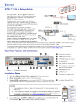
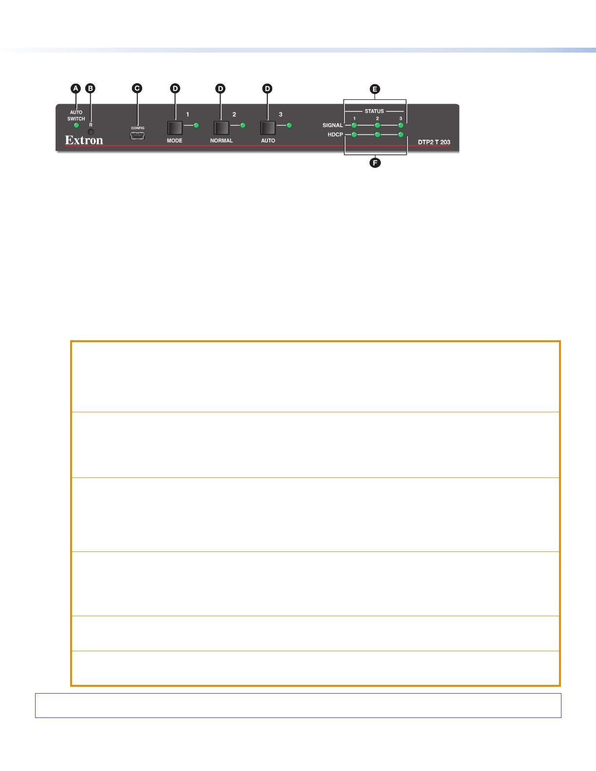
Front Panel
A
Auto Switch LED — Lights green when auto-input switching is enabled.
B
Reset Button — Accesses reset modes when pressed.
C
USB Config port — Updates rmware and congures the device through SIS commands or software control.
D
Input selection buttons — Selects the active input and used to change switching modes. Each button has an
associated LED which lights green to indicate input selection status. If auto-input switching is in effect, these buttons are
disabled, but the LEDs continue to light to indicate the selected input.
To enable or disable the auto-input switching mode via the front panel, press and hold the Input
1 (MODE) button
until it ashes, then press either the Input
2 (NORMAL) button to enable normal switching or the Input 3 (AUTO)
button to enable auto-input switching.
E
Input Signal LEDs — Lights green when a signal is detected on the associated input.
F
Input HDCP LEDs — Lights green when HDCP presence is detected on the associated input.
Figure 5. DTP2 T 203 Front Panel
ATTENTION:
Always use a power supply provided by or specied by Extron. Use of an unauthorized power supply voids all regulatory
compliance certication and may cause damage to the supply and the end product.
Utilisez toujours une source d’alimentation fournie ou recommandée par Extron. L’utilisation d’une source d’alimentation
non autorisée annule toute conformité réglementaire et peut endommager la source d’alimentation ainsi que le produit
nal.
The installation must always be in accordance with the applicable provisions of National Electrical Code ANSI/NFPA
70, article 725 and the Canadian Electrical Code part 1, section 16. The power supply shall not be permanently xed to
building structure or similar structure.
Cette installation doit toujours être conforme aux dispositions applicables du Code américain de l’électricité (National
Electrical Code) ANSI/NFPA 70, article 725, et du Code canadien de l’électricité, partie1, section16. La source
d’alimentation ne devra pas être xée de façon permanente à la structure de bâtiment ou à d’autres structures similaires.
Power supply voltage polarity is critical. Incorrect voltage polarity can damage the power supply and the unit. The ridges
on the side of the cord identify the power cord negative lead (see figure 4 on page3. To verify the polarity before
connection, plug in the power supply with no load and check the output with a voltmeter.
La polarité de la source d’alimentation est primordiale. Une polarité incorrecte pourrait endommager la source
d’alimentation et l’unité. Les stries sur le côté du cordon permettent de repérer le pôle négatif du cordon d’alimentation
(voir figure 4 sur la page3). Pour vérier la polarité avant la connexion, brancher l’alimentation hors charge et mesurer
sa sortie avec un voltmètre.
The length of the exposed wires in the stripping process is important. The ideal length is 3/16 inches (5 mm). Any longer
and the exposed wires may touch, causing a short circuit between them. Any shorter and the wires can be easily pulled
out even if tightly fastened by the captive screws.
La longueur des câbles exposés est importante lorsque l’on entreprend de les dénuder. La longueur idéale est de 5mm
(3/16inches). S’ils sont trop longs, les câbles exposés pourraient se toucher et provoquer un court-circuit. S’ils sont trop
courts, ils peuvent être tirés facilement, même s’ils sont correctement serrés par les borniers à vis.
Unless otherwise stated, the AC/DC adapters are not suitable for use in air handling spaces or in wall cavities.
Sauf mention contraire, les adaptateurs CA/CC ne conviennent pas à une utilisation dans les espaces d’aération ou dans
les cavités murales.
Remote power is intended for indoors use only. No part of a network that uses remote power can be routed outdoors.
L’alimentation à distance est exclusivement réservée à un usage en intérieur. Un réseau utilisant une alimentation à
distance ne peut pas être routé en extérieur.
  • Page 1 1
  • Page 2 2
  • Page 3 3
  • Page 4 4

Extron electronics DTP2 T 203 User manual

Type
User manual

Ask a question and I''ll find the answer in the document

Finding information in a document is now easier with AI

in other languages