Page is loading ...

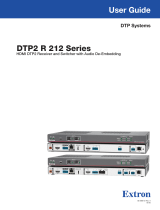
DTP2T204 • Setup Guide
The Extron DTP2 T 204 is an HDCP-compliant, four
input HDMI switcher with a DTP2 output that switches
and extends digital embedded audio, bidirectional
RS-232, IR, and remote power.
It supports video resolutions up to 4K @ 60 Hz and
1080p @ 120 Hz, using shielded twisted pair cabling as
a transmission medium, and extends HDMI video signals
up to 330 feet (100 meters).
The switcher features four HDMI inputs and a
DTP2/HDBT output, data rates up to 18 Gbps, HDR,
12 bit Deep Color, 3D, Lip Sync, HD lossless audio
formats, and SIS to CEC control. EDID Minder®
maintains EDID communication with connected devices
and ensures that the HDMI sources power up properly
and maintain correct video output.
Control is available via front panel buttons, USB, Extron
Product Control Software (PCS), Ethernet, RS-232,
contact closure, and auto-input switching for integration
with any control system. Front panel LED indicators provide immediate visual conrmation of HDCP authentication and signal
presence for each input and output. Remote power for the end unit is available via the DTP output.
This guide provides instructions for an experienced installer to set up and operate this switcher. For full installation,
conguration, and operation details, see the DTPT204 User Guide, available at www.extron.com.
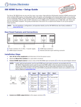
Rear Panel Features and Connections
INPUTS
OVER TP
DTP2 T 204
1 2 3 4
LAN
RS-232 IR
Tx Rx GTxRx
LINKSIG
OUT
Tx
TTCCT +VT
C
TG+V
C
TG+V
C
C
12 34
56
Rx
RS-232
G
2.2A
MAX
POWER
12V
REMOTE
CONT
HDBT
DTP
SEND POWER
OFF
A
B
C
D
E
F
G
H
F
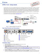
I
Figure 1. DTP2T204Rear Panel
Installation Steps
1. Turn off and disconnect all of the equipment from the power source.
2. Mount the switcher on a rack shelf or furniture (optional).
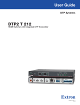
3. Connect HDMI input sources to one or more of the DTP2T 204 inputs (see figure1,
B
). The default (Extron) EDID is
present at each input and HotPlugDetect (HPD) is actively controlled on each input.
NOTES:
• The default (Extron) EDID is 1080p @ 60 Hz (see the DTP2T204 User Guide for the
EDID table).
• LockIt
®
cable lacing brackets are provided to secure the HDMI cables to the rear panel
connectors to reduce stress on the HDMI connectors and prevent signal loss due to
loose cable connections (see the LockIt Lacing Brackets on page4).
4. Connect the input of a DTP2 or HDBaseT compatible device to the DTP/HDBT OUT
RJ-45 connector (
C
). See the image at right to wire the connector.
INPUTS
OVER TP
DTP2 T 204
12 34
LAN
RS-232 IR
Tx Rx GTxRx
LINKSIG
OUT
Tx
TTCCT
+V
T
C
TG+V
C
TG+V
C
C
12 34
56
Rx
RS-232
G
2.0AMAX
POWER
12V
REMOTE
CONT
HDBT
DTP
SEND POWER
OFF
L
RS-232 IR
Tx Rx TxRxG
R
POWER
12V
--A MAX
AUDIO
OUTPUTS
OVER DTP2
SIG LINK
DTP2 IN
POWER
12V
0.3A MAX
IPL PRO S3
G
Tx Rx RTSCTS
G
Tx Rx RTSCTS
G
Tx Rx RTSCTS
COM 1 COM 2 COM 3
LAN / PoE
SHARE
SHARE
SHARE
MODEL 80
FLAT PANEL
LAN
LAN
ON OFFMUTE
HDMI
Ethernet
Extron
DTP2 T 204
Transmitter
Extron
IPL Pro S3
IP Link Pro
Control Processor
Extron
DTP2 R 211
Receiver
Ethernet
CATx Cable
up to 330' (100 m)
Flat Panel Display
HDMI
RS-232
Extron
CCR 30
Contact Closure Remote
with Three LED Switches
ON/OFF/MUTE Control
Extron
HDMI SM
Show Me Cables
1
Wire color
White-green
Green
White-orange
White-blue
Orange
White-brown
Brown
Blue
TIA/EIA T
568 B
TP Wires
12345678
Pins:
5
Pin
1
2
3
6
7
8
4
A
Power input connector
B
HDMI input connectors
C
DTP/HDBT Output RJ-45 port
D
TP mode switch
E
Over TP RS-232 and IR port
F
Contact input and
tally output
ports with +V connectors
G
Remote RS-232 port
H
LAN RJ-45 port
I
Remote power toggle switch
1
IMPORTANT:
IMPORTANT:
Go to www.extron.com for the complete
user guide, installation instructions, and
specifications before connecting the
product to the power source.

5. Set the TP mode switch (
D
) to HDBT (up) or DTP (down) as follows:
• If the receiving device is an Extron DTP device, set the switch to DTP.
• If the receiving device is HDBaseT enabled, set the switch to HDBT.
When the output is congured for DTP mode, remote power is available. When the output is congured for HDBT mode,
remote power is disabled and the switcher and receiver each require its own 12 VDC power supply.
ATTENTION:
• Position this switch before connecting the appropriate device to the TP connector. Failure to comply can damage
the endpoint.
• Positionnez le sélecteur avant de connecter l’appareil approprié au connecteur TP. Ne pas respecter cette
procédure pourrait endommager le point de connexion.
• Do not connect these devices to a computer data or telecommunications network.
• Ne connectez pas cet appareil à un réseau de télécommunications ou de données informatiques.
6. Connect Over TP RS-232 and IR control. Connect a serial RS-232 signal,
a modulated IR signal, or both into this 3.5 mm, 5-pole captive screw connector
(see figure1,
E
, on the previous page) for bidirectional RS-232 and IR
communication (see the image on the right to wire the RS-232 and IR connector).
7. Connect control devices. Connect your computer to one of the following
DTP2T204 communication ports to configure and control
the switcher via SIS commands or PCS:
• RS-232 port — Connect the unterminated transmit,
receive, and ground wires of the RS-232 cable to the
three pins on the provided 3-pole captive screw plug,
as shown in the image at right. Connect the plug to the
rear panel Remote RS-232 connector (
G
), and the
other end of the cable to your computer serial port.
Protocol for the RS-232 port is 9600 baud, 8 data
bits, 1 stop bit, and no parity.
• Config port — Connect a USB mini-B cable to the
front panel USB connector (see figure2,
B
, on the
next page) for USB control.
• LAN port — To control the DTP2 T 204 through Ethernet, connect a LAN to the RJ-45 LAN connector (see figure 1,
H
). The default IP address of the scaler is 192.168.254.254, the default subnet mask is 255.255.255.0, and the default
gateway address is 0.0.0.0. (See the diagram in step 4 on the previous page to wire this connector.)
8. (Optional) Connect contact closure and tally indicator devices. The Contact/Tally
section of the rear panel (
B
, on the previous page) contains four captive screw
connectors, each containing two pairs of pins labeled C and T (see
1
,
3
,
5
, and
6
in the image at right). Each C-T pin pair is labeled with its contact input number (1
through 6), and each individual pin is labeled with its function:
• C = Contact closure input
• T = Tally output
• G = Ground (for example,
4
)
• +V = +V connector for the tally output power wire (for example,
2
)
To enable input switching via contact closure, connect a contact closure device to a
contact-tally port as follows:
a. Connect a push-button contact closure device to a C pin of one of the contact-tally connectors.
b. Connect the ground wire of the contact device to one of the G pins.
c. If desired, to identify the currently selected input when the front panel LEDs are not visible, connect an indicator device,
such as an LED, to tally output pin (T) to the right of the connected C pin. When the input you are using is selected, the
corresponding tally out pin shorts to ground, which activates the connected indicator.
d. Insert the LED+ wire of the indicator device into a +V connector.
e. Press the button on the contact closure device to switch the connected input to the output.
Ground
Receive pin
Transmit pin
Connected RS-232
and IR Device Pins
Receive pin
Transmit pin
RS-232
IR
Tx Rx Tx RxG
Tx/Rx
Pins
Computer or
Control Syste
m
RS-232 Port
DTP2 T 204 Switcher
Rear Panel
Remote Port
NOTE: If you use cable that has a drain
wire, tie the drain wire to ground at both ends.
Ground (G)
Transmit (Tx)
Receive (Rx)
Transmit (Tx)
Receive (Rx)
Tx Rx G
RS-232
CONT
5
12 34
G
6
C+
VTGC+VT
C+VTCTCTCT
RxTx
G
RS-232
22
4
4
4
5
5
5 6
6
6
3
3
3
1
1
1
REMOTE
OFF
SEND
POWER
2
DTP2 T 204 • Setup Guide (Continued)

Contact/Tally ports operate in four modes depending on the needs and conguration of the user. These modes can be
selected and congured via SIS Commands or PCS
.
The modes are as follows:
• Mode 0 — (Default) Inputs 1 through 4 are grouped and mutually exclusive. Inputs 5 and 6 are independent.
• Mode 1 — Inputs 1 through 6 are independent and must be configured via SIS commands or PCS.
• Mode 2 — Inputs 1 through 4 are grouped and mutually exclusive. Inputs 5 and 6 are grouped
and mutually exclusive.
• Mode 3 — Inputs 1 through 4 are mutually exclusive. Inputs 5 and 6 are in single switch mode.
Using a Show Me cable:
The Contact and Tally connectors can also be used with Extron SM Series (Show Me) cables. The
diagram at right shows an example of how to wire an Show Me cable to a contact input.
For each Show Me cable:
• Connect the red pigtail to the C pin corresponding to the input being used.
• Connect the black pigtail to the T pin of the same input.
9. Connect power (see figure1,
A
, on page 1). Connect an
IEC power cord between the included 12 VDC, 3 A power supply and
a 100-240 VAC, 50-60 Hz source. Use the included tie-wrap to strap
the cord to the captive screw connector (see the diagram at right for
wiring).
ATTENTION:
• The wires must be kept separate while the power supply is plugged in. Remove power before wiring.
• Les deux cordons d’alimentation doivent être maintenus séparés lorsque la source d’alimentation est branchée.
Coupez l’alimentation avant d’effectuer un raccordement.
• The power supply must not be permanently fixed to the building structure or similar structures.
• La source d’alimentation ne devra pas être fixée de façon permanente à une structure de bâtiment ou à une
structure similaire.
• These power supplies are not suitable for use in air handling spaces or in wall cavities.
• Ces sources d’alimentation ne sont pas appropriées pour une utilisation dans les espaces d’aération ou dans les
cavités murales.
• Do not connect power to the switcher until you have read the CAUTION and ATTENTION notices on pages 5 and 6
of the DTP2 T 204 User Guide.
• Ne branchez pas l’alimentation au DTP2 T 204 User Guide avant d’avoir lu les mises en garde « CAUTION » et
«ATTENTION » aux pages 5 et 6.
10. Power on the output display.
11. Power on the source devices.
Front Panel Features
R
AUTO
SWITCH
CONFIG
DTP2 T 204
INPUTS OUTPUT
SIGNAL
HDCP
12
HDMI SWITCHER
1
INPUTS
34
w
2
43
C
C
C
DDD
F
B
B
B
A
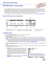
E
Figure 2. DTP2T204 Front Panel
A
Auto Switch LED — Lights when auto-input switching is in effect (see for more information). When auto-input switching is
enabled, the switcher automatically switches to the highest-number input with an active video signal.
B
USB Config port — Connect a USB cable (USB A to mini-B) between your computer and this female USB mini-B port to
configure and control the switcher via SIS commands or PCS and to update the firmware.
Contact/Tally
Connector
Black
Red
Show Me
Cable
CT
C
T
+V
1
2
SECTION A–A
Ridges
Smooth
A
A
3/16"
(5 mm) Max.
POWER
12 V
2.2 A MA
X
A
Auto Switch LED
B
USB Config port
C
Input and output signal
LEDs
D
HDCP LEDs
E
Input selection buttons
F
Reset button
2
3
3

For information on safety guidelines, regulatory compliances, EMI/EMF compatibility, accessibility, and related topics, see the
Extron Safety and Regulatory Compliance Guide on the Extron website.
© 2020 Extron — All rights reserved. www.extron.com
All trademarks mentioned are the property of their respective owners.
Worldwide Headquarters: Extron USA West, 1025 E. Ball Road, Anaheim, CA 92805, 800.633.9876
C
Input and output signal LEDs
• Inputs — Light when a source is connected to the corresponding input connector and TMDS clock activity is detected.
• Output — Lights when a video output is actively sent on the DTP/HDBT output.
D
HDCP LEDs
• Inputs — Light for each input if the connected sources are HDCP-encrypted and have been authenticated by the
switcher.
NOTE: If the source device connected to the selected input is HDCP encrypted (requires HDCP authentication), the
corresponding signal LED may not light unless HDCP has been authenticated.
• Output — Lights when the HDCP has been authenticated between the output of the switcher and the sink device
connected.
NOTE: HDCP is re-authenticated on the output whenever a new input is selected.
E
Input selection buttons — Press one of these buttons to select an input to switch to the output. The green LED at the right
of each button lights when the corresponding input is selected. If auto-input switching is in effect, these buttons are disabled,
but the LEDs continue to light to indicate the selected input. The input buttons are also used to initiate a system reset and to
enable and disable front panel lockout (see the DTP2T204 User Guide for more information).
F
Reset button — This button initiates three modes of reset for the switcher. For the different reset levels, press and hold the
button while the switcher is running or while you power up the switcher. (For more information about reset modes, see the
DTP2 T 204 User Guide at www.extron.com.)
LockIt Lacing Brackets
Use the included LockIt lacing brackets to securely fasten the HDMI cables to each device as follows.
1
Plug the HDMI cable into the rear panel connection.
2
Loosen the HDMI connection mounting screw from the panel enough to allow the
LockIt lacing bracket to be placed over it. The screw does not have to be removed.
3
Place the LockIt lacing bracket on the screw and against the HDMI connector, then tighten
the screw to secure the bracket.
ATTENTION:
• Do not overtighten the HDMI connection mounting screw. The shield it fastens
to is very thin and can easily be stripped.
• Ne serrez pas trop la vis de montage du connecteur HDMI. Le blindage auquel
elle est attachée est très fin et peut facilement être dénudé.
4
Loosely place the included tie wrap around the HDMI connector and the LockIt lacing
bracket as shown.
5
While holding the connector securely against the lacing bracket, use pliers or similar
tools to tighten the tie wrap, then remove any excess length.
3
1
2
3
4
5
4
68-3277-50 Rev. A
08 20
/