Page is loading ...

User Guide
DTP2R212 Series
DTP Systems
HDMI DTP2 Receiver and Switcher with Audio De-Embedding
68-2986-01 Rev. B
01 21

Safety Instructions
Safety Instructions • English
WARNING: This symbol, , when used on the product, is intended to
alert the user of the presence of uninsulated dangerous voltage within the
product’s enclosure that may present a risk of electric shock.
ATTENTION: This symbol, , when used on the product, is intended
to alert the user of important operating and maintenance (servicing)
instructions in the literature provided with the equipment.
For information on safety guidelines, regulatory compliances, EMI/EMF
compatibility, accessibility, and related topics, see the Extron Safety and
Regulatory Compliance Guide, part number 68-290-01, on the Extron
website, www.extron.com.
Sicherheitsanweisungen • Deutsch
WARNUNG: Dieses Symbol auf dem Produkt soll den Benutzer
darauf aufmerksam machen, dass im Inneren des Gehäuses dieses
Produktes gefährliche Spannungen herrschen, die nicht isoliert sind und
die einen elektrischen Schlag verursachen können.
VORSICHT: Dieses Symbol auf dem Produkt soll dem Benutzer in der im
Lieferumfang enthaltenen Dokumentation besonders wichtige Hinweise
zur Bedienung und Wartung (Instandhaltung) geben.
Weitere Informationen über die Sicherheitsrichtlinien, Produkthandhabung,
EMI/EMF-Kompatibilität, Zugänglichkeit und verwandte Themen finden Sie in
den Extron-Richtlinien für Sicherheit und Handhabung (Artikelnummer
68-290-01) auf der Extron-Website, www.extron.com.
Instrucciones de seguridad • Español
ADVERTENCIA: Este símbolo, , cuando se utiliza en el producto,
avisa al usuario de la presencia de voltaje peligroso sin aislar dentro del
producto, lo que puede representar un riesgo de descarga eléctrica.
ATENCIÓN: Este símbolo, , cuando se utiliza en el producto,
avisa al usuario de la presencia de importantes instrucciones de uso y
mantenimiento recogidas en la documentación proporcionada con el
equipo.
Para obtener información sobre directrices de seguridad, cumplimiento
de normativas, compatibilidad electromagnética, accesibilidad y temas
relacionados, consulte la Guía de cumplimiento de normativas y seguridad
de Extron, referencia 68-290-01, en el sitio Web de Extron, www.extron.com.
Instructions de sécurité • Français
AVERTISSEMENT : Ce pictogramme, , lorsqu’il est utilisé sur le
produit, signale à l’utilisateur la présence à l’intérieur du boîtier du
produit d’une tension électrique dangereuse susceptible de provoquer
un choc électrique.
ATTENTION : Ce pictogramme, , lorsqu’il est utilisé sur le produit,
signale à l’utilisateur des instructions d’utilisation ou de maintenance
importantes qui se trouvent dans la documentation fournie avec le
matériel.
Pour en savoir plus sur les règles de sécurité, la conformité à la
réglementation, la compatibilité EMI/EMF, l’accessibilité, et autres sujets
connexes, lisez les informations de sécurité et de conformité Extron, réf.
68-290-01, sur le site Extron, www.extron.com.
Istruzioni di sicurezza • Italiano
AVVERTENZA: Il simbolo, , se usato sul prodotto, serve ad
avvertire l’utente della presenza di tensione non isolata pericolosa
all’interno del contenitore del prodotto che può costituire un rischio di
scosse elettriche.
ATTENTZIONE: Il simbolo, , se usato sul prodotto, serve ad avvertire
l’utente della presenza di importanti istruzioni di funzionamento e
manutenzione nella documentazione fornita con l’apparecchio.
Per informazioni su parametri di sicurezza, conformità alle normative,
compatibilità EMI/EMF, accessibilità e argomenti simili, fare riferimento
alla Guida alla conformità normativa e di sicurezza di Extron, cod. articolo
68-290-01, sul sito web di Extron, www.extron.com.
I

Copyright
© 2020 – 2021 Extron. All rights reserved.
Trademarks
All trademarks mentioned in this guide are the properties of their respective owners.
The following registered trademarks(
®
), registered service marks(
SM
), and trademarks(
TM
) are the property of RGBSystems, Inc. or Extron
(see the current list of trademarks on the Terms of Use page at www.extron.com):
Registered Trademarks
(
®
)
Extron, Cable Cubby, ControlScript, CrossPoint, DTP, eBUS, EDID Manager, EDID Minder, Flat Field, FlexOS, Glitch Free, Global
Configurator, GlobalScripter, GlobalViewer, Hideaway, HyperLane, IPIntercom, IPLink, KeyMinder, LinkLicense, LockIt, MediaLink,
MediaPort, NAV, NetPA, PlenumVault, PoleVault, PowerCage, PURE3, Quantum, Show Me, SoundField, SpeedMount, SpeedSwitch,
StudioStation, SystemINTEGRATOR, TeamWork, TouchLink, V-Lock, VideoLounge, VN-Matrix, VoiceLift, WallVault, WindoWall, XTP,
XTPSystems, and ZipClip
Registered Service Mark
(SM)
: S3 Service Support Solutions
Trademarks
(
™
)
AAP, AFL (Accu-RATEFrameLock), ADSP(Advanced Digital Sync Processing), AVEdge, CableCover, CDRS(ClassD Ripple Suppression),
Codec Connect, DDSP(Digital Display Sync Processing), DMI (DynamicMotionInterpolation), DriverConfigurator, DSPConfigurator,
DSVP(Digital Sync Validation Processing), eLink, EQIP, Everlast, FastBite, Flex55, FOX, FOXBOX, IP Intercom HelpDesk, MAAP,
MicroDigital, Opti-Torque, PendantConnect, ProDSP, QS-FPC(QuickSwitch Front Panel Controller), RoomAgent, Scope-Trigger,
ShareLink, SIS, SimpleInstructionSet, Skew-Free, SpeedNav, Triple-Action Switching, True4K, Vector™ 4K , WebShare, XTRA, and
ZipCaddy

FCC Class A Notice
This equipment has been tested and found to comply with the limits for a Class A digital device,
pursuant to part15 of the FCC rules. The ClassA limits provide reasonable protection against harmful
interference when the equipment is operated in a commercial environment. This equipment generates,
uses, and can radiate radio frequency energy and, if not installed and used in accordance with the
instruction manual, may cause harmful interference to radio communications. Operation of this
equipment in a residential area is likely to cause interference. This interference must be corrected at
the expense of the user.
ATTENTION:
• The Twisted Pair Extension technology works with unshielded twisted pair (UTP)
or shielded twisted pair (STP) cables; but to ensure FCC Class A and CE
compliance, STP cables and STP Connectors are required.
• La technologie extension paires torsadées fonctionne avec les câbles paires
torsadées blindées(UTP) ou non blindées(STP). Afin de s’assurer de la
compatibilité entre FCC ClasseA et CE, les câbles STP et les connecteurs STP
sont nécessaires.
NOTES:
• This unit was tested with shielded I/O cables on the peripheral devices. Shielded
cables must be used to ensure compliance with FCC emissions limits.
• For more information on safety guidelines, regulatory compliances, EMI/EMF
compatibility, accessibility, and related topics, see the Extron Safety and
Regulatory Compliance Guide on the Extron website.

Conventions Used in this Guide
Notifications
The following notifications are used in this guide:
WARNING: Potential risk of severe injury or death.
AVERTISSEMENT : Risque potentiel de blessure grave ou de mort.
CAUTION: Risk of minor personal injury.
ATTENTION : Risque de blessuremineure.
ATTENTION:
• Risk of property damage.
• Risque de dommages matériels.
NOTE: A note draws attention to important information.
TIP: A tip provides a suggestion to make working with the application easier.
Software Commands
Commands are written in the fonts shown here:
^AR Merge Scene,,0p1 scene 1,1 ^B 51 ^W^C.0
[01] R 0004 00300 00400 00800 00600 [02] 35 [17] [03]
E X! *X1&* X2)* X2#* X2! CE}
NOTE: For commands and examples of computer or device responses mentioned
in this guide, the character “0” is used for the number zero and “O” is the capital
letter “o.”
Computer responses and directory paths that do not have variables are written in the font
shown here:
Reply from 208.132.180.48: bytes=32 times=2ms TTL=32
C:\Program Files\Extron
Variables are written in slanted form as shown here:
ping xxx.xxx.xxx.xxx —t
SOH R Data STX Command ETB ETX
Selectable items, such as menu names, menu options, buttons, tabs, and field names are
written in the font shown here:
From the File menu, select New.
Click the OK button.
Specifications Availability
Product specifications are available on the Extron website, www.extron.com.
Extron Glossary of Terms
A glossary of terms is available at http://www.extron.com/technology/glossary.aspx.


viiDTP2 R 212 Series • Contents
Contents
Introduction ................................................1
About this Guide .................................................. 1
About the DTP2R212 ........................................ 1
Features ............................................................. 2
Application Diagrams ........................................... 5
Installation .................................................. 7
Installation Overview ............................................ 7
Rear Panel Features ............................................ 8
Wiring Connections ........................................... 12
Power Connector .......................................... 12
LAN Connector Wiring ................................... 14
TP Connector and
Cable Recommendations ............................. 14
Analog Audio Output Connector .................... 15
Display and Remote RS‑232 Control ............. 16
Remote Control (SA models only) .................. 16
Over DTP2 RS‑232 and IR Control ................ 17
LockIt Lacing Brackets ...................................... 18
Operation.................................................. 19
Front Panel Features .......................................... 19
Operations......................................................... 20
Powering on the Receiver .............................. 20
Selecting an Input .......................................... 20
Front Panel Lockout (Executive Mode) ........... 21
Connecting to the USB Port .............................. 21
Configuration ..................................................... 23
Enabling Auto‑Input Switching ....................... 23
EDID Minder .................................................. 23
HDCP ............................................................ 24
Audio Configuration ....................................... 24
Configuration Software .............................25
Software Installation........................................... 25
Connecting to PCS ............................................ 26
Opening PCS ................................................ 26
Software Overview ............................................. 27
PCS Device Menu ......................................... 27
Software Menu .............................................. 28
Updating Firmware ............................................ 31
Downloading DTP2R212 Firmware .............. 31
Uploading Firmware to the Switcher .............. 32
SIS Commands ......................................... 35
Using Simple Instruction Set (SIS) Commands ... 35
Host‑to‑switcher Communications ................ 35
Switcher‑initiated Messages .......................... 35
Password Messages ..................................... 36
Error Responses ............................................ 36
Timeout ......................................................... 37
Unsolicited Responses .................................. 37
Using the Command and Response Table ..... 37
Symbol Definitions ............................................. 38
Command and Response Table for SIS
Commands ..................................................... 42
Command and Response Table for CEC
Communications SIS Commands .................... 51
Internal Web Page ..................................... 54
Accessing the Internal Web Page ...................... 54
Disabling Compatibility Mode ......................... 55
Web Page Panels .............................................. 55
Device Info Panel ........................................... 56
Device Status Panel ....................................... 56
Network Settings Panel ................................. 57
Firmware Panel .............................................. 58
Roles and Permissions Panel ......................... 59

DTP2 R 212 Series • Contents viii
Mounting .................................................. 60
Mounting the DTP2R212 ................................. 60
Tabletop Use ................................................. 60
Rack Mounting .............................................. 60
Furniture Mounting......................................... 60

DTP2 R 212 Series • Introduction 1
Introduction
This section gives an overview of the Extron DTP2R 212 and DTP2 R 212 SA switching
receivers. Topics include:
• About this Guide
• About the DTP2R212
• Features
• Application Diagrams
About this Guide
This guide describes the DTP2R212 and DTP2R212 SA two‑input switching receivers
and provides instructions on how to install, configure, and operate them. The DTP2R212
switches and extends signals up to 330 feet (100 meters).
Details regarding configurating and operating the receivers through the Extron Product
Configuration Software (PCS) can be found in the DTP2R212 PCS Help File available after
you’ve opened up PCS (see PCS Device Menu on page27).
In this guide, the DTP2R212 and DTP2R212 SA are commonly referred to as “receiver”,
“switcher”, “switching receiver”, or simply as DTP2R212.
About the DTP2R212
The Extron DTP2R212 is a two‑input switcher for 4K video signals with two simultaneous
outputs. The switching receiver features one HDMI and one DTP2 input, and one local
HDMI output. The device also features EDID Minder for managing EDID, and Key Minder for
managing HDCP outputs.
The DTP2R212 can also extract embedded HDMI two‑channel PCM audio to a stereo
captive screw output or an optional stereo amplifier output (DTP2 R 212 SA).
• The DTP2R212 receives the digital signal from Legacy DTP inputs up to 330feet
(100meters) with a maximum resolution of up to 4K @ 60 Hz, 4:2:0, with HDCP1.4,
supporting data rates up to 10.2Gbps.
• The DTP2R212 receives the digital signal from DTP2 inputs up to 330feet
(100meters) with a maximum resolution of up to 4K @ 60 Hz, 4:4:4, with HDCP2.3,
supporting data rates up to 18Gbps.
The switcher is housed in a one‑inch high, three‑quarter rack wide, rack‑mountable metal
enclosure, and is powered by an external power supply.

DTP2 R 212 Series • Introduction 2
Features
• Receives HDMI plus control and analog audio up to 330 feet (100 meters)
over a shielded CATx cable — The DTP2 R 212 models provide high reliability and
maximum performance on an economical and easily installed cable infrastructure.
• HDMI and DTP2 inputs
• HDMI input is ideal for connecting to a local source, such as a laptop or
ShareLink wireless collaboration gateway
• Supports computer and video resolutions up to 4K/60 @ 4:4:4 — Support of
4K/60 at 4:4:4 chroma sampling requires connection to a matching DTP2 product.
• Auto-switching between inputs — Auto‑switching allows for simple, unmanaged
installation. When multiple inputs are active, the switching priority is configurable.
• Supported HDMI 2.0b specification features include data rates up to 18 Gbps,
HDR, Deep Color up to 12-bit, 3D, HD lossless audio formats, and CEC
• Support for HDR – High Dynamic Range video — Enables greater contrast range
and wider color gamut by providing the necessary video bandwidth, color depth, and
metadata interchange capability for HDR video.
• HDCP 2.3 compliant — Ensures display of content‑protected 4K video media and
maintains interoperability with earlier versions of HDCP.
• Stereo audio de-embedding — Embedded HDMI two‑channel PCM audio can be
extracted to the stereo captive screw output or the optional stereo amplifier output.
• DTP2 R 212 SA model features energy efficient class D stereo amplifier
• 90 dB signal-to-noise ratio with 0.1% THD+N — Ensures quiet, low‑noise
amplification and maintains audio signal integrity for exceptional performance in a
compact, economical amplifier.
• Extron-patented CDRS™ - Class D Ripple Suppression — CDRS is an
Extron Patented technology that provides a smooth, clean audio waveform and an
improvement in signal fidelity over conventional Class D amplifier designs. CDRS
eliminates the high frequency switching ripple characteristic of Class D amplifiers,
a source of RF emissions which can interfere with sensitive AV equipment such as
wireless microphones.
• Automatic clip limiter — Detects actual onset of clipping by comparing input and
output waveforms. Gain is automatically reduced without audible artifacts to protect
speakers from clipping distortion.
• Selectable volume control — Allows the output volume to be remotely controlled
via SIS or using an optional Extron VCM 110 or VCM 200 analog volume and mute
controller or the VC 50 analog volume controller.
• 25.8 watts rms output power: 2 x 12.9 watts @ 4 ohms or 2 x 7.6 watts
@ 8 ohms — Used in combination with surface mount or ceiling speakers, the
integrated amplifier provides a compact, economical audio solution for classrooms,
meeting rooms and other applications, providing a significant step‑up in sound
quality over the speakers built into displays.
• CEC - Consumer Electronics Control Capability — Standard, built‑in CEC
commands can be triggered to control displays or other AV devices connected to
the HDMI output. The ability to control specific functions, such as power on/off, input
selection, or volume level, is dependent on implementation by the device manufacturer.
• Extron XTP DTP 24 shielded twisted pair cable is strongly recommended for
optimal performance

DTP2 R 212 Series • Introduction 3
• Compatible with CATx shielded twisted pair cable — The DTP2R212 models fully
support a maximum transmission distance of 330 feet (100 meters) for all compatible
resolutions when used with CATx shielded twisted pair cable. Shielded twisted pair
cabling with solid center conductor sizes of 24 AWG or better is recommended for
optimal performance.
• Remote power capability with DTP2 products — For simplified installation, the
standard DTP2 R 212 without amplifier can be remotely powered by a DTP2 transmitter
over the twisted pair connection. It can also be configured to provide power to the
connected DTP2 transmitter.
• Accepts additional analog stereo audio signals — The DTP2R212 models accept
stereo analog audio from a DTP‑enabled product. This audio may be switched to the
stereo captive screw output or the optional stereo amplifier output, independent of the
video input selection.
• Stereo audio embedding — Pass‑through audio from the DTP input can be
embedded onto the HDMI output.
• Bidirectional RS-232 and IR pass-through for AV device control — Bidirectional
RS‑232 control and IR signals can be transmitted alongside the video signal, allowing
remote AV devices to be controlled without the need for additional cabling.
• RS-232 insertion from the Ethernet control port — Saves system resources and
simplifies installation by enabling a control processor to access remote RS‑232 devices
over Ethernet.
• Display control RS-232 port — Serial commands inserted from Ethernet can be
routed to this port to control a connected display or other device.
• Supports multiple embedded audio formats — The DTP2R212 models are
compatible with a broad range of multi‑channel audio signals, providing reliable
operation with HDMI sources.
• Compatible with all DTP transmitters and DTP-enabled products — Enables
mixing and matching with desktop and wallplate transmitters, as well as other DTP‑
enabled products to meet application requirements.
• User-selectable HDCP authorization — Allows the unit to appear HDCP compliant
or non‑HDCP compliant to the connected source, which is beneficial if the source
automatically encrypts all content when connected to an HDCP‑compliant device.
Protected material is not passed in non‑HDCP mode.
• Comprehensive EDID management — Use PCS software to access EDID Minder for
setting video input EDID, capturing EDID from connected displays, or uploading custom
EDID files. Proper EDID management ensures that sources and displays are easily
integrated into a system resulting in optimized system operation. Freely downloadable
EDID Manager 2.0 software is available for advanced EDID editing and creating custom
EDID files.
• EDID Minder automatically manages EDID communication between connected
devices — EDID Minder ensures that the source powers up properly and reliably
outputs content for display.
• HDCP authentication and signal presence confirmation — Provides real‑time
verification of HDCP status for each digital video input and output. This allows for
simple, quick, and easy signal and HDCP verification through front panel LEDs, RS‑232,
USB, or Ethernet, providing valuable feedback to a system operator or helpdesk
support staff.
• HDCP Visual Confirmation — When HDCP‑encrypted content is transmitted to
a non‑HDCP compliant display, a full‑screen green signal is sent to the display for
immediate visual confirmation that protected content cannot be viewed on that display.

DTP2 R 212 Series • Introduction 4
• HDMI to DVI Interface Format Correction — Automatically enables or disables
embedded audio and InfoFrames, and sets the correct color space for proper
connection to HDMI and DVI displays.
• Automatic color bit depth management — Automatically adjusts color bit depth
based on the display EDID, preventing color compatibility conflicts between source and
displays.
• Output muting control — Provides the capability to mute the HDMI and/or analog
audio output at any time.
• Bass and treble controls
• Selectable stereo or dual mono audio — Allows the user to choose between
stereo output, or to sum the left and right channels into dual mono outputs using SIS
command.
• Ethernet monitoring and control — Enables control and proactive monitoring over a
LAN, WAN, or the Internet.
• Built-in Web pages — Enables the use of a standard browser for device monitoring
and troubleshooting over an intuitive Web interface.
• Front panel security lockout — This feature locks out all front panel functions; all
functions however, are available through USB or RS‑232 control.
• RS-232 control port — Enables the use of serial commands for integration into
a control system. Extron products use the SIS ‑ Simple Instruction Set command
protocol, a set of basic ASCII commands that allow for quick and easy programming.
• Front panel USB configuration port — Provides convenient access for information
and firmware updates.
• LED indicators for signal presence, power, and link status — Provide visual
indication of system status for real‑time feedback and monitoring of key performance
parameters.
• RJ-45 signal and link LED indicators for DTP port — Provide a means for validating
signal flow and operation, allowing quick identification of connectivity issues.
• Easy setup and commissioning with Extron PCS - Product Configuration
Software — Conveniently configure multiple products using a single software
application.
• 1” (2.5 cm) high, three-quarter rack width metal enclosure — With a low profile
enclosure, the device can be installed discreetly wherever needed.
• Includes LockIt HDMI cable lacing brackets
• External Extron Everlast power supply included — Provides worldwide power
compatibility with high‑demonstrated reliability and low power consumption.
• Extron Everlast Power Supply is covered by a 7-year parts and labor warranty

DTP2 R 212 Series • Introduction 5
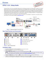
Application Diagrams
The following diagrams show typical applications for the DTP2R212 series.
CLASS 2
WIRING
4/8 OHM
1
2
L
R
Rx GTx
HDMI HDMI
RS-232IR
RxTx
OVER DTP2
Rx GTx
RS-232
DISPLAY
POWER
12V
3.0 A MAX
RS-232
RxTx G
INPUTS
OUTPUT
CVG
10V50mA
LR
VOL
REMOTE
R
DTP2 R 212 SA
LAN
OFF
SEND POWER
SIG LINK
DTP2 IN
POWER
12V
--A MAX
AUDIO
INPUTS
SIG LINK
DTP2 OUT
OVER DTP2
RS-232
IR
Tx Rx Tx RxG
INPUT
OFF
SEND
POWER
STATUS
OUTPUT
LINK
DTP2 T 211
CONFIG
POWER
12V
1A MAX
G
Tx Rx RTSCTS
COM 1
G
Tx Rx
COM 2
VCG
VOL
RELAYS
12C
1 2 3 4G
DIGITAL I/O
PWR OUT =6W
eBUS
+V +S
-S
G
LAN
IPCP PRO250
IR/S
SG
Extron
Extron
LAN
Extron
DTP2 R 212 SA
Receiver
Extron
SM 3
Surface Mount
Speakers
4K HDR Display
RS-232
HDMI
HDMI
RS-232
HDMI
CATx Cable
up to 330' (100 m)
PC with
4K HDR
Video Output
Extron
DTP2 T 211
Transmitter
Extron
IPCP Pro 250
IP Link Pro
Control Processor
Audio
4K Media Player
TLP Pro 725M
7" Wall Mount
Touchlink Pro
Touchpanel
Figure 1. Typical Switching Receiver Application
1

DTP2 R 212 Series • Introduction 6
DTP2 R 212 SERIES
CONFIG
AUTO
SWITCH
INPUTS
OUTPUT
12
SIGNAL
HDCP
INPUTS
1
MODE NORM/ AUTO
2
CLASS 2
WIRING
4/8 OHM
1
2
L
R
Rx GTx
HDMI HDMI
RS-232 IR
RxTx
OVER DTP2
Rx GTx
RS-232
DISPLAY
POWER
12V
3.0 A MAX
RS-232
RxTx G
INPUTS
OUTPUT
CVG
10V 50mA
LR
VOL
REMOTE
R
DTP2 R 212 SA
LAN
OFF
SEND POWER
SIGLINK
DTP2 IN
POWER
12V
23
--A MAX
Rx
G
Tx RxTxG
IR
RxTx
1
RGB
HDMI DP
HDBT
DTP
AUDIO
CONTACT IN
RS-232
TALLY OUT
123G123+V
INPUTS
OVER DTP
REMOTE
RS-232
SIG
OUT
LINK
LAN
MODEL 80
FLAT PANEL
Extron Extron
ShareLink Pro 1000
HD WIN
STANDBY
SCREEN
DECODER
HD PASS
HDMI DECODER
SIGNAL
HDCP
CONFIG
OUTPUTINPUT
HDMI
WINDOW
HDMI
PASS-THROUGH
12
USB
LAN
Extron
Cable Cubby
Extron
DTP2 R 212 SA
Receiver
Extron
SM 3
Surface Mount
Speakers
Audio
Flat Panel Display
RS-232
HDMI
Audio
VGA
HDMI
HDMI
DisplayPort
Laptop
Extron
Cable Cubby 700
Series/2 Cable
Access Enclosure
Wireless
Laptop
Tablet
Smartphone
Extron
DTP T DSW
4K 233
Transmitter
Extron
ShareLink Pro 1000
Collaboration Gateway
Ethernet
Ethernet
Ethernet
Facility/Room
Wireless Access Point
Laptop Laptop
AudioVGAHDMIDisplayPort
CATx Cable
up to 230'
(70 m)
Figure 2. Typical Switching Receiver Application
2

DTP2 R 212 Series • Installation 7
Installation
This section describes the installation and setup of the DTP2R212 switcher. Topics include:
• Installation Overview
• Rear Panel Features
• Wiring Connections
• LockIt Lacing Brackets
Installation Overview
To install and set up the DTP2R212 switching receiver:
1. Turn off all equipment and disconnect it from the power source.
2. Mount the switcher (optional) on a rack shelf or furniture (see Mounting the
DTP2R212 on page60).
3. Connect an HDMI input source to the DTP2R212 input. The default (Extron) EDID is
present and Hot Plug Detect (HPD) is actively controlled on the input.
NOTE: LockIt cable lacing brackets are provided to secure the HDMI cables to the
rear panel ports to reduce stress on the HDMI connectors and prevent signal loss
due to loose cable connections (see the LockIt Lacing Brackets on page18).
4. Connect an HDMI output device to the HDMI output. By default, the EDID of this
device is stored at the HDMI inputs.
5. Connect an RJ-45 DTP2 transmitting device to the DTP2 In connector (see
figure3,
D
, on page8), set the Send Power switch (
E
).
ATTENTION:
• Position this switch (see figure3,
E
) BEFORE connecting the appropriate
device to the TP connector. Failure to comply can damage the endpoint.
• Positionnez le sélecteur (voir figure3,
E
) AVANT de connecter l’appareil
approprié au connecteur TP. Ne pas respecter cette procédure pourrait
endommager le point de connexion.
• If the transmitting device is in the Extron DTP2 series and you are setting up the
DTP2R212 receiver to supply power to the transmitter:
• Set the receiver SEND POWER switch (
E
) to the “UP” (SEND POWER)
position (see figure4 on page10).
• Set the transmitter SEND POWER switch (
E
) to the “DOWN” (OFF) position.
• If the transmitting device is in the Extron DTP2 series and you setting up the
DTP2R212 (non‑amplifier model) to receive power from the transmitter:
• Set the receiver SEND POWER switch of the receiver (
E
) to the “DOWN”
(OFF) position (see figure4 on page10).
• Set the transmitter SEND POWER switch to the “UP” (SEND POWER)
position.

DTP2 R 212 Series • Installation 8
• If the transmitting device is in the Extron DTP2 series and you setting up the
DTP2R212 SA (amplifier model), you can only set the receiver to send power to
the transmitter:
• Set the receiver SEND POWER switch of the receiver (
E
) to the “UP” (SEND
POWER) position (see figure5 on page11).
• Set the transmitter SEND POWER switch of the transmitter to the “DOWN”
(OFF) position.
• If the transmitting device is in the Extron Legacy DTP series and not the DTP2
series, set the SEND POWER switches of both devices to the “DOWN” (OFF)
position (see figure4 on page10).
6. Connect Over DTP RS-232 and IR control. Connect a serial RS‑232 signal, a
modulated IR signal, or both into this 3.5mm, 5‑pole captive screw port (
C
) for
bidirectional RS‑232 and IR communication (see Over DTP2 RS-232 and IR Control
on page17 for connection procedures).
7. Connect control devices. Connect your computer to one of the following ports to
configure and control the device via SIS commands or PCS:
• RS-232 port — This 3‑pole RS‑232 port (
L
) for serial RS‑232 control (see
Display and Remote RS-232 Control on page16 for connection procedures).
• Config port — USB mini‑B port for USB control (see Connecting to the USB
Port on page21 for connection procedures).
• LAN (Ethernet) port — Connect an Ethernet cable for LAN control. LEDs on
the connector indicate link and activity status (see LAN Connector Wiring on
page14 for connection wiring).
8. Power on the output display.
9. Connect power to the switcher (see Powering on the Receiver on page20).
10. (Optional) Configure EDID Minder (see the DTP2R212 PCS Help File).
11. Power on the source devices.
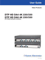
Rear Panel Features
1
2
Rx GTx
HDMI HDMI
RS-232
DTP2 R 212
IR
RxTx
OVER DTP2
Rx GTx
RS-232
DISPLAY
POWER
12V
2.0 A MAX
RS-232
RxTx G
INPUTS
OUTPUT
LAN
REMOTE
LR
OFF
SEND
POWER
R
SIGLINK
DTP2 IN
CLASS 2
WIRING
4/8 OHM
1
2
L
R
Rx GTx
HDMI HDMI
RS-232 IR
RxTx
OVER DTP2
Rx GTx
RS-232
DISPLAY
POWER
12V
3.0 A MAX
RS-232
RxTx G
INPUTS
OUTPUT
CVG
10V 50mA
LR
VOL
REMOTE
R
DTP2 R 212 SA
LAN
OFF
SEND POWER
SIGLINK
DTP2 IN
B DCA I J LKGF H M NE
**
*
A
Power inlet
H
Amplified audio output (SA models)
B
HDMI input
I
Display control
C
OVER DTP2 control
J
Remote amplified volume control
(SA models)
D
DTP2 IN RJ-45 port
K
Switch for volume control
(SA models)
E
Send Power toggle switch
L
Remote RS-232 port
F
HDMI output
M
LAN (Ethernet) port
G
Audio output
N
Reset button
Figure 3. Rear Panel Features
3

DTP2 R 212 Series • Installation 9
A
Power inlet — Plug the provided external 12VDC power supply into this 2‑pole,
3.5mm captive screw inlet and into an DC power outlet (see Power Connector on
page12).
NOTE: The DTP2 R 212 SA model is supplied with, and requires, a higher‑wattage
power supply (4.2 A, 50 Watts). The non‑SA model can use a standard 2.0 A,
24Watt supply.
B
HDMI input — Connect a HDMI video source to this female type A HDMI connector.
This port can also accept DVI video with appropriate adapter.
NOTE: LockIt cable lacing brackets are provided to secure the HDMI cables to the
rear panel ports and reduce stress on the connectors, preventing signal loss due
to loose cable connections (see LockIt Lacing Brackets on page18).
C
OVER DTP2 control — Connect a serial RS‑232 signal, a modulated IR signal,
or both into this 3.5mm, 5‑pole captive screw port for bidirectional RS‑232 and IR
communication (see Over DTP2 RS-232 and IR Control on page17 to wire the
connector).
D
DTP2 IN RJ-45 port — Plug one end of a DTP2 cable to this RJ‑45 female port.
Plug the opposite end of this cable into the DTP port on a compatible transmitter (see
TP Connector and Cable Recommendations on page14 to wire the RJ‑45
connector and NOTES on page15).
• Signal LED — Lights green when the unit is sensing a TMDS clock signal on the
DTP2 input.
• Link LED — Lights amber to indicate a valid link is established between the units.
ATTENTION:
• Do not connect this device to a telecommunications or computer data network.
• Ne connectez pas cet appareil à un réseau de télécommunications ou de
données informatiques.
E
Send Power toggle switch (see figure3 on page8) — The Send Power switch
enables or disables the sending of power from the receiver to a DTP2 transmitter.
Set the toggle switch to the UP (Send Power) position on the powered DTP2 unit to
enable sending remote power to the other device. Set the toggle switch to the DOWN
(OFF) position on the DTP2 unit receiving power.
NOTES: Guidelines for setting the Send Power switch:
• If you are using the DTP2 R 212 SA (amplified audio) receiver, the power output
of the DTP2 transmitter is not enough to power the receiver. You can send
power from the receiver to the transmitter, but not from the transmitter to the
receiver (see figure5 on page11).
• If you are using the DTP2 R 212 receiver (not the SA model), the power output
of the DTP2 transmitter is enough to power the receiver. You can send power
either way, if desired (see figure4 on page10).

DTP2 R 212 Series • Installation 10
ATTENTION:
• The DTP2R212 device is configured to send or receive power with other
DTP2 models only. If connected to a Legacy DTP device, set the SEND
POWER toggle switch to the “DOWN” position (OFF). Failure to turn the power
OFF will damage the connected DTP device (see figure4).
• Le DTP2R212 est configuré pour fournir une alimentation aux modèles
DTP2 uniquement. S’il est connecté à un autre appareil, veuillez positionner
l’interrupteur à bascule sur « DOWN » (OFF). Si l’interrupteur n’est pas
positionné sur OFF, vous risquez d’entraîner la défaillance de l’appareil Legacy
DTP connecté (voir figure4).
1
2
Rx GTx
HDMI HDMI
RS-232
DTP2 R 212
IR
RxTx
OVER DTP2
Rx GTx
RS-232
DISPLAY
POWER
12V
2.0 A MAX
RS-232
RxTx G
INPUTS
OUTPUT
LAN
REMOTE
LR
OFF
SEND
POWER
R
SIG LINK
DTP2 IN
SEND
POWER
OFF
OFF
DTP2 T 211
CONFIG
INPUT
LINK
OUTPUT
SEND
POWER
OFF
STATUS
DTP HDMI 330 Tx
1
2
Rx GTx
HDMI HDMI
RS-232
DTP2 R 212
IR
RxTx
OVER DTP2
Rx GTx
RS-232
DISPLAY
POWER
12V
2.0 A MAX
RS-232
RxTx G
INPUTS
OUTPUT
LAN
REMOTE
LR
OFF
SEND
POWER
R
SIG LINK
DTP2 IN
SEND
POWER
OFF
OFF
SEND
POWER
OFF
ON
DTP2 T 211
CONFIG
INPUT
LINK
OUTPUT
SEND
POWER
OFF
STATUS
1
2
Rx GTx
HDMI HDMI
RS-232
DTP2 R 212
IR
RxTx
OVER DTP2
Rx GTx
RS-232
DISPLAY
POWER
12V
2.0 A MAX
RS-232
RxTx G
INPUTS
OUTPUT
LAN
REMOTE
LR
OFF
SEND
POWER
R
SIG LINK
DTP2 IN
SEND
POWER
OFF
ON
SEND
POWER
OFF
OFF
DTP2 T 211
CONFIG
INPUT
LINK
OUTPUT
SEND
POWER
OFF
STATUS
CATx Cable
up to 330' (100 m)
No Remote Power
Local
Power Supply
Extron
DTP2 R 212
Receiver
Extron
DTP HDMI 4K 330 Tx
Transmitter
CATx Cable
up to 330' (100 m)
Direction of
Remote Power
CATx Cable
up to 330' (100 m)
Direction of
Remote Power
Extron
DTP2 R 212
Receiver
Extron
DTP2 T 211
Transmitter
Extron
PS 1220
(2 A, 24 Watts)
Local
Power Supply
Extron
DTP2 R 212
Receiver
Extron
DTP2 T 211
Transmitter
Extron
PS 1220
(2 A, 24 Watts)
Figure 4. DTP2 R 212 (non-SA) Send Power Toggle Switch Configuration
4

DTP2 R 212 Series • Installation 11
CLASS 2
WIRING
4/8 OHM
1
2
L
R
Rx GTx
HDMI HDMI
RS-232 IR
RxTx
OVER DTP2
Rx GTx
RS-232
DISPLAY
POWER
12V
3.0 A MAX
RS-232
RxTx G
INPUTS
OUTPUT
CVG
10V 50mA
LR
VOL
REMOTE
R
DTP2 R 212 SA
LAN
OFF
SEND POWER
SIG LINK
DTP2 IN
SEND
POWER
OFF
OFF
DTP2 T 211
CONFIG
INPUT
LINK
OUTPUT
SEND
POWER
OFF
STATUS
DTP HDMI 330 Tx
CLASS 2
WIRING
4/8 OHM
1
2
L
R
Rx GTx
HDMI HDMI
RS-232 IR
RxTx
OVER DTP2
Rx GTx
RS-232
DISPLAY
POWER
12V
3.0 A MAX
RS-232
RxTx G
INPUTS
OUTPUT
CVG
10V50mA
LR
VOL
REMOTE
R
DTP2 R 212 SA
LAN
OFF
SEND POWER
SIG LINK
DTP2 IN
SEND
POWER
OFF
ON
SEND
POWER
OFF
OFF
DTP2 T 211
CONFIG
INPUT
LINK
OUTPUT
SEND
POWER
OFF
STATUS
CATx Cable
up to 330' (100 m)
No Remote Power
Extron
PS 1242
(4.2 A, 50 Watts)
Local
Power Supply
Extron
DTP2 R 212 SA
Receiver
Extron
DTP HDMI 4K 330 Tx
Transmitter
DTP2 Endpoint Connected to a DTP2 Endpoint
CATx Cable
up to 330' (100 m)
Direction of
Remote Power
Extron
DTP2 R 212 SA
Receiver
Extron
DTP2 T 211
Transmitter
Extron
PS 1242
(4.2 A, 50 Watts)
Figure 5. DTP2 R 212 SA Send Power Toggle Switch Configuration
F
HDMI output — Connect an HDMI display device to this female Type A HDMI port. The
EDID information is read from the connected output device via this port and is written
to memory on each input whenever the output device is connected to this port and
powered on.
NOTE: The EDID information is also read and stored whenever power is recycled to
the connected output device or when the output device is replaced.
G
Audio output — Connect a 5‑pole captive screw connector for balanced or
unbalanced analog audio output. This audio output is not amplified and can be
connected to an external amplifier.
H
Amplified audio output (SA models only) — Connect a 4‑pole captive screw
connector for amplified audio output to external speakers.
I
Display control — Use 3‑pole captive screw connector for bi‑directional RS‑232
control of a connected display device.
J
Remote amplified volume control port (SA models only) — Connect an external
audio controller to control volume and mute levels remotely via this 3.5mm, 3‑pole
captive screw port (see Remote Control (SA models only) on page16 for more
information and to wire the connection).
K
Switch for volume control (SA models only) — When using the amplified output
connector (
H
), flip the switch to the lower position for remote volume control of the
amplified output through port
J
.
L
Remote RS-232 port — Connect a serial RS‑232 device via this 3.5mm, 3‑pole
captive screw port for remote control of the DTP2 R 212 (see Display and Remote
RS-232 Control on page16 to wire the connector).
5

DTP2 R 212 Series • Installation 12
M
LAN (Ethernet) port — Use an RJ‑45 cable to connect this jack to a LAN (Ethernet)
for control of the device.
N
Reset button — With a tweeker or other pointed tool, press and hold the recessed
reset button:
• Press and hold for 3 seconds to reset back to factory default. IP settings are
retained.
• Press and hold for 10 seconds to reset back to factory default. IP settings are reset
to default.
• Press and hold while powering the unit on enables the unit to revert to factory
default firmware version and factory default setting.
NOTE: The receiver can also be reset to factory settings using SIS commands (see
Reset on page50) or PCS (see PCS Device Menu on page27).
Wiring Connections
Power Connector
A 12VDC power supply is provided with the DTP2R212. Follow these instructions to wire
the 2‑pole captive screw connector to your power supply:
CAUTION: The DC output cables must be kept separate from each other while the
power supply is plugged in. Remove power before wiring.
ATTENTION : Les câbles de sortie CC doivent être séparés les uns des autres tant que
la source d’alimentation est branchée. Coupez l’alimentation avant d’effectuer tout
raccordement.
ATTENTION:
• Do not connect power to the DTP2 R 212 until you have read the ATTENTION
notifications on the next page.
• Ne branchez pas l’alimentation au DTP2 R 212 avant d’avoir lu les mises en garde
« ATTENTION » en page suivante.
1. Cut the DC output cord to the length needed.
2. Strip the jacket to expose 3/16inch (5mm) of the conductors (see figure6).
3. Slide the leads into the supplied 2‑pole captive screw connector and secure them,
using a small screwdriver.
SECTION A–A
Ridges
Smooth
A
A
3/16"
(5 mm) Max.
POWER
12V
--A MAX
Figure 6. Wiring the Power Connector
4. To verify the power cord polarity before connecting the plug, connect the power supply
with no load and check the output with a voltmeter.
5. Use the supplied tie wrap to strap the power cord to the extended tail of the connector.
6
/