Page is loading ...

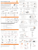
Quick Installation Guide
X3-Forth 40.0kW-150.0kW
Packing List
Mounting the inverter on the wall
Bracket
Nut
- Use the bracket as a template for marking the - Hammer the M8x80 expansion screw
into four holes.
- Drill the four holes with a φ10 drill.
- Depth: at least 65 mm. - Screw in the nut firmly with socket wrench.
- Lift up the inverter.
- Two methods are available
by four installers or lifting ring
position of holes with a level and marker.
Expansion screw
-Hang it onto the bracket - Fix it on the wall bracket with M8 bolts
Mounting the inverter on the stand
Bracket
M10x40 screw
- Use a bracket as a template for marking the - Screw in the M10x40 screw into holes.
- Drill the four holes with a drill.
- Tighten it firmly with corresponding
socket wrench.
position of the holes with a level and marker.
- Lift up the inverter.
- Two methods are available
by four installers or lifting right
- Hang it onto the bracket - Fix it on the stand with M8 bolts
- Insert the stripped section into OT terminal.
- Pull the heat-shrink tubing over grounding cable
- And crimp with crimping tool
A=B+(2~3mm)
B
- Strip the 35-70 mm²grounding cable insulation
- Select OT copper terminal (M8)
C=A+2 cm
- Pull the heat-shrink tubing onto crimped section of OT terminal
- The tubing must be at below stripped cable section
- Use hot-air blower to shrink it
so that they are in firm contact with OT terminal
- Connect the grounding cable to grounding
point on the inverter
- Tighten it with torque 10-12 N.m
Grounding connection
- Pull the heat-shrink tubing over the crimped section of OT terminal.
-Use hot air blower to shrink it so that they are in firm contact with OT terminal.
Heat-shrink tubing
Grid connection
PV connection
- Disassemble the DC contactor
Positive DC contactor
Positive PV pin
Positive terminal
Fastening head
Negative DC contactor
Negative PV pin
Negative terminal
Fastening head
6 mm
Cable size: 10 AWG
- Strip the PV cable insulation
- Connect the PV cable to the corresponding PV port
+
-
+
-
PV 2 PV 4
I
I
Tighten the fastening head
Positive DC
PV pin
Negative DC
PV pin
Clamp pin
(Torque: 3-4 N·m)
Positive terminal
Negative terminal
*Note: The double offset ring wrench in the accessory bag is used to remove the screws on the front cover of the inverter. Keep it in a safe place
*Note: Screws used for installation on the wall are not in the accessory bag. Please prepare them in advance.
Communication connector x1
Double offset ring wrench x1
X3-Forth inverter x1
Positive DC pin contact x24
Negative DC pin contact x24
Bracketx1
M10xL40 Bolt combination x4
M8Boltx2
Female DC connectorx24
Male DC connectors x24
WiFi (Optional)
Installation guide x1
Installation guide
X3-Forth 40.0kW-150.0kW
A
D+(2~3) mm
BA≤260 mm
B≤150 mm
a≤45 mm
12.5≤b≤15 mm
D
L1 / L2 / L3 / N
L1
L2
L3
N
PE
- Select the appropriate OT terminal and 70~240 black, red and yellow and green copper cable mm²
- use wire stripper to strip the insulation layer of the AC cable end.
-The stripped insulation layer shall be 2-3mm longer
than “D” part of OT terminal as shown below.
- Pull the heat-shrink tubing over AC cable.
- Insert the stripped section into OT terminal and crimp with crimping tool.
Separate PE cable Multi-corecable
-Un-install the screws on the cover to open the cover of the wiring box.
-Use utility knife to cut out the pagoda type protection ring in accordance with the whole cable size,
-Put the AC cable through the pagoda protection ring, and connect it to the AC terminals L1, L2, L3 and N in turn,
and tighten it with torque wrench (with the torque of 25-30 N·m).
-Re-install the cover of wiring box with the torque of 5~7 N·m.
User manual x1

V
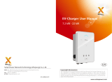
Communication connection
PV connection
20-25 mm 12-14 mm
- Select 0.5~0.75 mm² twisted-pair and strip the 20-pin communication insulation
- Insert the insulated cord end terminal into the cable end
(ENY0512 nylon terminal for 0.5mm²/22 AWG conductor;
ENY7515 nylon terminal for 0.75 mm²/20 AWG conductor)
- Clamp with terminals press clamp
Body, Seal ring, Seal body, Claw, nut
- Disassemble the communication terminal
- Set the nut, claw, seal body, seal ring and body on the cable
- Insert the tube type terminal into the housing
according to the label
- Push the terminal-inserted housing into the body;
you will hear “Click” , if it is correctly inserted
- Please check the following table for more details about
corresponding Pin definition
Housing
Make sure that the inverter is fixed on the wall.
Communication Connection(BMS/Meter/CT/COM/DRM)Grounding Connection(manodatory)
Communication connection
- Push the seal body into seal ring, then push the claw
Clockwise tighten the nut with torque 8+/-2 N.m
- Keep the buttons on both sides pressed
and then connect it to the communication
port on the inverter. You will hear
“Click” if it is correctly connected
Inverter RS485 networking or
connectthedatacollector
Port Pin Definition Remark
RS-485-1
RS-485-2
DRM
1
2
3
4
5
6
7
8
9
10
11
12
13
14
15
16
RS485A IN+
RS485B IN-
Rs485 IN-GND
RS485A OUT+
RS485B OUT-
RS485A METER
RS485B METER
V+5V
COM_GND
DRM1/5
DRM2/6
DRM3/7
DRM4/8
RG/0
CL/0
Rs485OUT-GND
ConnecttheRS485 meter or
other devices
Reserved for DRM
DI
21
22
Digital IN+
Digital IN-
Inputdigitalsignal
DO
29
30
Digital OUT+
Digital OUT-
Outputdigitalsignal
Monitoring connection
614.00664.02
Monitoring connection
Basic settings can set the time, date, language and system switch.
Advanced settings can set the new password of the inverter, buzzer enable, timing
switch, etc.
-Under different standard codes, the parameters that can be set for the inverter are
different.
-If you change the grid standard code, some parameters may revert to factory
defaults. After the grid standard code is changed, please check whether the
previously set parameters are affected.
-Sending reset, plant recovery, shutdown or upgrade instructions to the inverter
may cause the inverter to be unable to be connected to the grid and affect power
generation.
-The power grid parameters, protection parameters, characteristic parameters and
power regulation parameters of the inverter must be set by professionals. power
grid
Incorrect setting of parameters, protection parameters and characteristic parameters
may cause the inverter not connected to the grid and incorrect setting of power
adjustment parameters.
-The error may cause that the inverter cannot be connected to the power grid
according to the power grid requirements, thus affecting the power generation.
-Parameter name, ranges, and defaults may change or adjust in the future.
ØBasic setting
ØAdvanced setting
Parameters setting
Solaxcloud is a mobile phone application that can communicate with the inverter via
WiFi/LAN/4G. It can realize alarm query, parameter configuration, daily maintenance and other
functions. This is a convenient maintenance platform.
Plug Dongle into “USB” port at the bottom of the inverter. After the DC side or AC side is
powered on, the APP and inverter can be connected. Please refer to the corresponding
manual for details.
Router
SolaX Cloud
Router
SolaX Cloud
ØWiFi connection
ØLAN connection
Solax Pocket WiFi Dongle connects to a local network within 50 m of the
installation to enable access to the SolaX Cloud monitoring platform.
If WiFi isn’t suitable, the Pocket LAN enables users to connect to the network
via an ethernet cable. Ethernet allows for a much more stable connection with
less interference.
Ø4G connection
SolaX Pocket 4G dongle allows you to use a 4G connection to monitor your
system without the option of connecting to a local network. (This product is not
available in the UK)
1/2