Page is loading ...

IIII
II
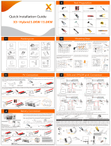
Quick Installation Guide
X1 Series 3.0KW-6.0KW
Packing Lists
Inverter Installation
PV Connection
Female DC connector * 2
Male DC connector * 2
AC connector * 1
- Unscrew the bracket from the back of the inverter.
- And mark the position(223 mm*30 mm) of three holes.
- Drill holes with φ10 drill.
- Depth: at least 60 mm.
- Screw the expansion screws. - Match the inverter with the bracket.
- Screw the cross recessed screw on the right side.
- make sure available space
strip length:
7.0 mm
-Align the four halves connectors.
positive DC
pin contact
male plug
Earth terminal * 1
Positive DC pin contact * 2
Negative DC pin contact * 2 nut female plug
tight nut
negative DC
pin contact
clamp contact
cable
Inverter
PV array
PV1
PV2
+
-
+
-
+
-
+
-
+
-
Note!
The PV connection
mode as the diagram
shown is not
allowed!
×
Inverter
(with bracket)* 1
223
30
- Tighten the expansion s.bolt
X1
Pocket WiFi * 1(Optional)
X1
300 mm
300 mm
300 mm
300 mm
300 mm
Cable size: 4 mm²
Expansion bolt*3
Flat gasket*3
Self-tapping screw*3
Documents
Wi-Fi dongle (optional),
LAN/GRPS dongle (optional)*1
Earth terminal*1
PH1 cross screwdriver; Torque: 0 .8±0.1 N.m
Torque: 0.8±0.1 N.m
* For the optional accessories, please be subject to the actual delivery.

V
IV
Connections and Overview
Firmware Upgrading
AC Connection
1.Slide the cable nut and
back shell onto the cable.
2.Insert the stripped end of each three
wires into holes in the female insert,
then tighten each screw.
N
L
PE
5.Connect the AC plug to the inverter.
- Screw the ground screw with Φ4 hexagon wrench shown as follow.
- Overview for connection. - After checking all connections are correct, turn on the external
DC /AC breakers.
- Inverter will start automatically when PV panels generate
enough energy. The LED will be blue and the LCD screen
will display the main interface.
- Turn on the DC switch to the “ON” position.
320102024902
Firmware Upgrading
1) Make sure the DC switch is off and the AC is disconnected with grid. User can update the inverter system through the U-disk.
Please contact SolaX service to get the latest firmware. Then add a new folder named "Update" in the root directory on your U-disk, and
two more sub-folders named "ARM" and "DSP" under "Update". Please copy the firmware files into ARM and DSP respectively. It will be
like:
“Update\ARM\618.00207.00_XX_XXXXX_XXXX_XXX_ARM_Vx.xx_xxxxxxxx.usb”;
“Update\DSP\618.00381.00_XX_XXXXX_XXXX_XXX_DSP_Vx.xx_xxxxxxxx.usb”
2) Press and hold the “v” key for 5 seconds to enter Off Mode. Then insert the U-disk into the "DONGLE" port.
- Prepare the RJ45 connector and the communication cable, following the PIN
definition and assembly order below, then insert the RJ45 connector into the
corresponding RS485 port of the inverter, and tighten the waterproof connector.
1
8
For the inverter with LCD, user can refer to the following:
Ø
3) When the user turns on all the switches, the LCD will show pictures as below.
And at the same time, the user can choose the program you need by pressing short Up
and Down, and long press “V” to confirm and upgrade the inverter.
4) After the upgrade is complete, please remember to turn off the DC switch and AC switch, then pull off the U-
disk.
* Please contact our service support to get the latest firmware, and unzip it into your U-disk by
following the steps above.
Do not modify the firmware file name ! Otherwise it may cause damage to the inverter!
ARM
DSP
Cancel
OK
Update(ARM)
Updating----25%
Update(ARM)
>618.00207.00... ...
ARM
DSP
Update(DSP)
Updating----25%
Update(DSP)
>618.00381.00... ...
PIN
Definition
1 4
Meter_A/
7
E_Stop
5
Meter_B/
8
RefGen
2
Com/DRM0
3
GND_COM
6
CT-
485_A 485_B
CT+
strip length
52.5mm
6mm
55mm
outer jacket
4.Screw down the pressure screw.
3.Screw down the threaded sleeve of the pressure screw.
L,N cable(mm²) Inverter+BMU
X1-3.0/ /3.3 3.6K
Model X1-4.2/4.6K
Micro-breaker 20A 25A
PE cable(mm²)
2.5-6
2.5-6
4-6
5-6
X1-5.0/5.5/6K
32A
2.5-6
5-6
CT/DRM/Meter/RS485
CT
L line
Public grid, inverter side
→
AC port
arrow point to
the public grid
RS485 port DRM/Meter/RS485
Ph1 cross screwdriver; Torque: 0 .5±0.1 N.m
Torque:1.5±0.2 N.m
Torque:1.0±0.1N.m
/