Page is loading ...

X1-Matebox advanced
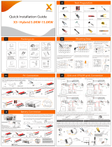
Quick Installation Guide
Load
Grid
X1-Matebox is a critical part for SolaX all in one energy
storage system, which integrates the AC breaker/switch
unit/CT and so on. It can easily be installed compared to
the traditional separate system. This unit can be used with
SolaX X1-Hybrid G4 and X1-Fit G4 series inverters.
There are 2 wiring diagrams for your system connection
reference, please follow your local policy to choose which
one is suitable for your side.
Diagram A: Neutral line and PE line are separated
from each other, all loads connect to the EPS (Off-
grid) port;
Diagram B: Neutral line and PE line are combined
together, all loads connect to the EPS (Off-grid)
port.
1. Introduction
2. Overview
3.1 Check Packing List
Open the package and check the materials and accessories according the following list.
3. Preparation
3.2 Tools
The bracket of the matebox is composed of three parts.
Bracket A is used to install the matebox. Bracket B is
used to fix the bracket position of the inverter, and
Bracket C is used to fix the bracket position of the
battery.
4. Mounting
First of all, connect inverter bracket, Bracket B, Bracket A, Bracket C and BAT bracket all together with
flange nuts.
Step 1: Connect all brackets
Then set bracket C on bracket A; Then bracket C is fixed on BAT bracket and the
screws are locked.
Fix the inverter bracket on bracket B; Then set bracket B on bracket A and fix it with
screws;
Step 2: Connect the BAT bracket and battery and push the whole structure to the wall
Note: The position of the battery base
mounting screws are two positions on the
inner side, refer to the following figure.
Screw
Step 3: Fix the position, drill holes and install the whole structure on the wall
a) With the position of the brackets as a template in
step 2, use a spirit level to mark the holes needed
on the wall with a marker pen.
b) Move away the structure and drill holes at marked
spots with depth of 60 mm.
c) Insert expansion bolts into the holes, use rubber
hammer to knock the expansion bolts into the wall.
d) The brackets are aligned with the screws, use the
inner hexagonal wrench to screw the tapping
screws until the expansion bolt "bang" is heard.
Step 4: Install inverter
Object Name Description
A B C D E
F G H I J
BAT
CAN
CT
BAT(INV)
CT connection port of the inverter
EPS (Off-grid)1 output port of the inverter
Grid1 output port of the inverter
Grid connection port (to local grid)
EPS (Off-grid)1
Grid1
Grid
EPS (Off-grid)2
Grid2
Battery connection port (to battery pack)
Reserved
Reserved
Reserved
A
B
C
D
E
F
G
H
I
JBattery connection port of the inverter
Load connection port
Load
b)
Step 5: Install matebox
a) Cut off the strips of the box except the strips on the back of the box before installing the box. Open the
unlocked buckler of the matebox, open the upper cover and remove the protective cover; (open the
button by hand, open the cover and slide upwards.)
b) Put the matebox on the bracket. Make sure the box is well fixed on the bracket by screwing all nuts
tightly.
a)
(Expansion bolt,
Gasket, Self-tapping
bolt) x2
N-terminal adjacent
bridge x1
(for AU market)
European terminal
6 mm x6, 16 mm x4
Documents
60 mm
Matebox x1
BROWN
BULE
BROWN
BULE
Yellow/Green
Yellow/Green
BROWN
BULE
BROWN
BULE
AC cable x1
EPS cable x1
AC waterproof
cover x1
Bracket B x1
Bracket C x1
Key x4
PE
L
N
L
N
509 mm
437 mm
185 mm
Philips screwdriver
Torque: 1.5±0.2 N·m
Philips screwdriver
Torque: 1.5±0.2 N·m
d)
c)
b)
a) Φ10 drill
Expansion bolts
Rubber hammer
External hexagonal wrench
Monkey wrench
Torque: 1.5±0.2 N·m
Monkey wrench
Torque: 1.5±0.2 N·m
Monkey wrench
Torque: 1.5±0.2 N·m
Monkey wrench
Torque: 1.5±0.2 N·m
BAT bracket
Bracket C
Bracket A
Bracket B
Inverter bracket
BAT bracket
Bracket C
Bracket A
Bracket B
Inverter bracket
Matebox
Bracket A x1
Flange nut x4
Inverter
X1-Matebox
Battery
Inverter
X1-Matebox
Battery
Distribution Box Distribution Box
Grid
Grid
Grid EPS
(Off-grid)
Grid EPS
(Off-grid)
Main Breaker Main Breaker
E-BAR E-BAR
Breaker
Breaker
Loads
Loads
N-BAR for loads N-BAR for loads
BAT CT
PV1
PV2
BAT CT
PV1
PV2
Diagonal plier Philips screwdriver Φ10 Drill Monkey wrench
Crimping plier
Crimping tool Hexagon keys Marker pen Rubber hammer
Make sure all brackets (bracket A, bracket B, bracket C, inverter bracket and BAT bracket) are well and firmly
installed.
b)
a)
b) Hang the buckle on the inverter to the
corresponding position of the backplane.
c) Use the inner hexagonal wrench to tighten the
inner hexagonal screw on the right side of the
inverter.
c) d)
a) Take the AC waterproof cover from the matebox
(instead of the one from D version inverter) and
connect the AC cable and EPS cable through the
AC waterproof cover to the inverter. (For details,
please refer to the documents of the inverter.)
Inverter
Battery
Inner hexagonal
wrench
Torque: 1.2±0.1 N·m
6 mm BAT terminal x2
Battery adapter line
positive x1, negative x1
Earthing conductor
(400 mm x1, 250 mm
x2)
16 mm R-type
terminal x1 WiFi dongle x1
External/Inner
hexagonal wrench

6. Wiring Connection
a) According to the BAT(INV)+ / BAT(INV)- line symbol on the matebox, insert the lines into the
corresponding BAT + / BAT- ports of the inverter.
b) Connect the CT cable of the matebox to the CT port of the inverter, and tighten the waterproof plug.
6.1 Inverter side connection
7. Technical Parameters
Rated Grid Voltage, Frequency
Rated Grid Voltage, Frequency
6.2 Matebox side connection
1) Open the protective cover. Connect the Grid1 L/N and EPS (Off-grid)1 L/N/PE lines between the inverter
and the matebox. The connection method is as follows:
a) First, insert Grid1 L/N and EPS (Off-grid)1 L/N into the matebox port firmly, and then gently pull to check
if they are connected properly and screw the waterproof plug tightly;
b) Connect the Grid (PE), use a philips screwdriver to tighten the screws.
2) Grid(L/N/PE) /Load(L/N) side connection.
a) Grid(L/N/PE) /Load(L/N) wire, remove the 12 mm insulation layer at the end of the wire. Insert The
European terminals respectively. The stripped terminals must be inserted into the European terminals and
finally pressed down with the crimping pliers.
13 mm
b) Grid(PE) strip the grounding cable, remove the 13 mm insulation layer at the end of the wire. Insert the
stripped cable into the R-type terminal, and then clamp it.
c) Pass the Grid/Load line through the Grid/Load port of the matebox, then find the Grid (L/N) and Load
(L/N) ports in the matebox, insert each line accordingly, and use the screwdriver to lock the screws.
Grid (PE) is secured with a philips screwdriver.
3) Take out the power cable from the BMS accessories, and cut it to 560-600 mm and strip 7 mm of the
insulation layer from the wire ends. Crimp the 6 mm BAT terminals on the wires. Then pass the cable
through the BAT port of the matebox, then find the BAT+ and BAT- ports in the matebox, insert each wire
accordingly, and use the philips screwdriver to lock the screws.
Earth bar
6.3 Ground wire connections
There are three parts that need to be grounded, one is between the inverter and the matebox, one
between the matebox and the battery and the other between the upper cover and the matebox.
6.4 Battery's communication wire connection
- When the distance between the matebox and the battery is < 1 m, you can use the BMS communication
line in the accessory bag.
- When the distance between the matebox and the battery is > 1 m, you need to prepare the regular
network cable and find the RJ45 terminal of the accessory package to make the cable.
The BMS port connection between the inverter and the battery (for the specific connection method,
please refer to the inverter and battery quick installation guide):
6.5 N lines short circuit (applicable in Australia)
- According to local regulations, the continuity of the neutral line of EPS load and that of the grid is not
interrupted when the inverter disconnects from the grid (for wiring Australia and New Zealand regulations
AS/ NZs_3000:2012).
- First, find N-terminal adjacent Bridge in the accessory package.
- Forcibly insert N-terminal adjacent bridge into the N-terminal hole and jam it. Twist gently and make sure
it would not become loose.
6.6 Finally, use a philips screwdriver to install the baffle back, install the upper cover,
and then lock the buckle with a key
⑦⑧⑨⑩
⑦⑧⑨⑩
N N
Battery Voltage Range
Max. Charge/Discharge Current
80-480 V d.c.
30 A/30 A
Max. Grid Input Current
Max. Load Current
185 mm * 509 mm * 437 mm
Dimension (L*W*H)
Weight
Operating Temperature
Installation
60 A
220/230/240 V a.c., 50/60 Hz
10 kg
-35℃~+60℃
Wall Mounted
60 A
220/230/240 V a.c., 50/60 Hz
b)
a)
12 mm
12 mm
320102048701
b)
a)
RJ45 terminal
N-terminal adjacent
bridge x1
Philips screwdriver
Torque: 1.5±0.2 N·m
Hexagon keys
Torque: 1.5±0.2 N·m
Philips screwdriver
Torque: 1.5±0.2 N·m
Philips screwdriver
Torque: 1.5±0.2 N·m
Grid(PE) Diagonal plier
Crimping tool
Diagonal plier Crimping plier
Grid(L/N) Load(L/N) Grid(L/N) Load(L/N)
Philips screwdriver
Torque: 1.5±0.2 N·m
Crimping plier
Max. Apparent Grid (INV) Input Power
Max. Apparent Grid (INV) Output Power
7500 VA
7500 VA
Installation Specifcation
Load
Grid Input/Output
DC Input/Output
7500 VA
Max. Apparent EPS Output Power
Philips screwdriver
Torque: 1.5±0.2 N·m
L=450 mm
55-60 mm
55-60 mm
c)
b)
a) Insert the WiFi dongle into the Dongle port of the inverter.
b) Take out the antenna from the box of monitoring accessories and install the antenna on bracket A
and tighten it by hand.
c) Then connect the antenna cable to the end of the WiFi dongle .
5. Monitoring Connection
a)
/