SoleX X3-EVC-11K EV Charger 7.2 kW – 22 kW User manual
- Type
- User manual

614.00623.01
SolaX Power Network Technology (Zhejiang) Co., Ltd.
EV-Charger User Manual
7.2 kW - 22 kW
Copyright Declaration
The copyright of this manual belongs to SolaX Power Network Technology (Zhejiang) Co., Ltd.
Any corporation or individual should not plagiarize, partially or fully copy it (including
software, etc.), and no reproduction or distribution of it in any form or by any means shall be
allowed. All rights reserved. SolaX Power Network Technology (Zhejiang) Co., Ltd. reserves the
right of final interpretation.
ADD.: No. 288, Shizhu Road, Tonglu Economic Development Zone,
Tonglu City, Zhejiang Province, China.
TEL.: +86 571-56260011
E-mail: info@solaxpower.com

Contents
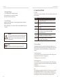
01
1 Note on this Manual. . . . . . . . . . . . . . . . . . . . . . . . . . . . . . . . . . . . . . . . . . 03
1.1 Scope of Validity . . . . . . . . . . . . . . . . . . . . . . . . . . . . . . . . . . . . . . . . . . . . . . . . . . . . . 03
1.2 Target Group. . . . . . . . . . . . . . . . . . . . . . . . . . . . . . . . . . . . . . . . . . . . . . . . . . . . . . . . . 03
1.3 Symbols Used. . . . . . . . . . . . . . . . . . . . . . . . . . . . . . . . . . . . . . . . . . . . . . . . . . . . . . . . 03
2 Safety . . . . . . . . . . . . . . . . . . . . . . . . . . . . . . . . . . . . . . . . . . . . . . . . . . . . . . . . 04
2.1 Appropriate Usage . . . . . . . . . . . . . . . . . . . . . . . . . . . . . . . . . . . . . . . . . . . . . . . . . . 04
2.2 Important Safety Instructions . . . . . . . . . . . . . . . . . . . . . . . . . . . . . . . . . . . . . . . 05
2.3 Explanation of Symbols . . . . . . . . . . . . . . . . . . . . . . . . . . . . . . . . . . . . . . . . . . . . . 06
3 Introduction . . . . . . . . . . . . . . . . . . . . . . . . . . . . . . . . . . . . . . . . . . . . . . . . . 07
3.1 Basic Features . . . . . . . . . . . . . . . . . . . . . . . . . . . . . . . . . . . . . . . . . . . . . . . . . . . . . . . 07
3.2 Dimension . . . . . . . . . . . . . . . . . . . . . . . . . . . . . . . . . . . . . . . . . . . . . . . . . . . . . . . . . . . 08
3.3 Product Description . . . . . . . . . . . . . . . . . . . . . . . . . . . . . . . . . . . . . . . . . . . . . . . . . 10
4 Technical Data . . . . . . . . . . . . . . . . . . . . . . . . . . . . . . . . . . . . . . . . . . . . . . . 11
4.1 General Data. . . . . . . . . . . . . . . . . . . . . . . . . . . . . . . . . . . . . . . . . . . . . . . . . . . . . . . . . 11
4.2 Security Protection . . . . . . . . . . . . . . . . . . . . . . . . . . . . . . . . . . . . . . . . . . . . . . . . . . 12
5 Installation . . . . . . . . . . . . . . . . . . . . . . . . . . . . . . . . . . . . . . . . . . . . . . . . . . . 13
5.1 Check for Transport Damage . . . . . . . . . . . . . . . . . . . . . . . . . . . . . . . . . . . . . . . . 13
5.2 Packing List . . . . . . . . . . . . . . . . . . . . . . . . . . . . . . . . . . . . . . . . . . . . . . . . . . . . . . . . . . 13
5.3 Installation Precaution . . . . . . . . . . . . . . . . . . . . . . . . . . . . . . . . . . . . . . . . . . . . . . 14
5.4 Installation Steps . . . . . . . . . . . . . . . . . . . . . . . . . . . . . . . . . . . . . . . . . . . . . . . . . . . . 15
5.5 CT Connection. . . . . . . . . . . . . . . . . . . . . . . . . . . . . . . . . . . . . . . . . . . . . . . . . . . . . . . 24
5.6 Run the EV-Charger. . . . . . . . . . . . . . . . . . . . . . . . . . . . . . . . . . . . . . . . . . . . . . . . . . 26
6 Operation Method . . . . . . . . . . . . . . . . . . . . . . . . . . . . . . . . . . . . . . . . . . . 27
6.1 States . . . . . . . . . . . . . . . . . . . . . . . . . . . . . . . . . . . . . . . . . . . . . . . . . . . . . . . . . . . . . . . . 27
6.2 Start-up Patterns . . . . . . . . . . . . . . . . . . . . . . . . . . . . . . . . . . . . . . . . . . . . . . . . . . . . 27
6.3 Charging Modes . . . . . . . . . . . . . . . . . . . . . . . . . . . . . . . . . . . . . . . . . . . . . . . . . . . . . 28
6.3.1 GREEN Mode . . . . . . . . . . . . . . . . . . . . . . . . . . . . . . . . . . . . . . . . . . . . . . . . . . . . 28
6.3.2 ECO Mode . . . . . . . . . . . . . . . . . . . . . . . . . . . . . . . . . . . . . . . . . . . . . . . . . . . . . . . 29
6.3.3 FAST Mode . . . . . . . . . . . . . . . . . . . . . . . . . . . . . . . . . . . . . . . . . . . . . . . . . . . . . . 29
Contents

Contents Notes on this Manual
1.1 Scope of Validity
This manual is an integral part of the EV-Charger Series. It describes the assembly,
installation, commissioning, maintenance and failure of the product. Please read it
carefully before operating.
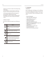
1 Notes on this Manual
DANGER!
“Danger” indicates a hazardous situation which, if not avoided,
will result in death or serious injury.
WARNING!
“Warning” indicates a hazardous situation which, if not avoided,
could result in death or serious injury.
CAUTION!
“Caution” indicates a hazardous situation which, if not avoided,
could result in minor or moderate injury.
NOTE!
“Note” provides tips that are valuable for the optimal operation of
your product.
Note:
”X1” means single-phase, ”X3” means three-phase.
”EVC” means “EV-Charger”.
“7.2K” means 7.2 kW, “11K” means 11 kW, “22K” means 22 kW.
”S” :, ”P”: Plug, . Socket, only socket outlet with charging cable and connector
”X” : without LCD screen.
“H”: home edition.
Keep this manual at where it is accessible all the time.
1.2 Target Group
This manual is for qualified electricians. The tasks described in this manual can only
be performed by qualified electricians.
1.3 Symbols Used
The following types of safety instructions and general information appear in this
document as described below:
0302
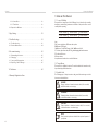
6.3.4 Smart Boost . . . . . . . . . . . . . . . . . . . . . . . . . . . . . . . . . . . . . . . . . . . . . . . . . . . . . 30
6.3.5 Timer Boost . . . . . . . . . . . . . . . . . . . . . . . . . . . . . . . . . . . . . . . . . . . . . . . . . . . . . 30
6.4 Dynamic Load Balance . . . . . . . . . . . . . . . . . . . . . . . . . . . . . . . . . . . . . . . . . . . . . . 31
7 App Setting...................................................32
8 Troubleshooting . . . . . . . . . . . . . . . . . . . . . . . . . . . . . . . . . . . . . . . . . . . . . 41
8.1 Troubleshooting. . . . . . . . . . . . . . . . . . . . . . . . . . . . . . . . . . . . . . . . . . . . . . . . . . . . . 41
8.2 Routine Maintenance . . . . . . . . . . . . . . . . . . . . . . . . . . . . . . . . . . . . . . . . . . . . . . . 44
9 Decommissioning ............................................45
9.1 Dismantling the Inverter . . . . . . . . . . . . . . . . . . . . . . . . . . . . . . . . . . . . . . . . . . . . 45
9.2 Packaging . . . . . . . . . . . . . . . . . . . . . . . . . . . . . . . . . . . . . . . . . . . . . . . . . . . . . . . . . . . 45
9.3 Storage and Transportation . . . . . . . . . . . . . . . . . . . . . . . . . . . . . . . . . . . . . . . . . 45
9.4 Disposing of the EV-Charger . . . . . . . . . . . . . . . . . . . . . . . . . . . . . . . . . . . . . . . . 45
10 Disclaimer...................................................46
* Warranty Registration Form
X1-EVC-7.2K(SXH)
X1-EVC-7.2K(PXH)
X3-EVC-11K(SXH)
X3-EVC-11K(PXH) X3-EVC-22K(PXH)
X3-EVC-22K(SXH)

Safety Safety
2 Safety
2.1 Appropriate Usage
The EV-Charger Series are AC EV charger, intended to be installed in a fixed location
and connected to the AC supply.
Electrical
grid
other home Load
PV array
AC distribution box
Inverter
CT/Meter
Electricity meter,
bidirectional
Electrical
grid
other home Load
PV array
AC distribution box
Inverter
Electricity meter,
bidirectional
Communication with CT/Meter
Communication with Inverter
Prior to the application, please read this section carefully to ensure correct and
safe application. Please keep the user manual properly.
Use only accessories recommended or sold by SolaX. Otherwise may result in a risk
of fire, electric shock, or injury to person.
Make sure that existing wiring is in good condition and that wire is not undersized.
Do not disassemble any parts of the EV-Charger which are not mentioned in
installation guide. It contains no user-serviceable parts. See Warranty for
instructions on obtaining service. Attempting to maintain the EV-Charger Series
by yourself may result in a risk of electric shock or fire and will void your warranty.
Keep away from flammable, explosive materials to avoid fire disaster.
The installation place should be away from humid or corrosive substance.
2.2 Important Safety Instructions
CAUTION!
Danger of burn injuries due to hot enclosure parts!
During operation, the EV-Charger may become hot.
CAUTION!
Incorrect operation or misuse may result in:
Injury or death to the operator or third parties.
Damage to the device and other property of the operator.
Inefficient operation of the device.
DANGER!
Danger to life due to output and input high voltages in this
device!
All work must be carried out by qualified electrician who
has knowledge of and experience in dealing with electrical
installations.
The device is not to be used by children or persons with reduced
physical sensory or mental capabilities, or lack of experience and
knowledge, unless they have been given supervision or
instruction.
Children should be supervised to ensure that they do not play
with the device.
Risk of electric shock!
WARNING!
0504
CT/Meter

2.3 Explanation of Symbols
This section gives an explanation of all the symbols shown on the EV-Charger type
label.
Symbol Explanation
CE mark.
The EV-Charger complies with the requirements of the applicable
CE guidelines.
Danger of high voltages.
Danger to life due to high voltages in the EV-Charger!
Danger.
Risk of electric shock!
The EV Charger can not be disposed together with household waste. -
Used electrical devices must be collected separately and recycled
in an environmentally responsible manner. Ensure that you return
your used device to your dealer or obtain information regarding a
local, authorised collection and disposal system.
The EV-Charger can be recycled.
Authorized service personnel must use insulated tools when installing or working
with this equipment.
Do not use the EV-Charger in case the device has defects, crack, abrasion, bare
leakage and so on. Please contact the working staff in case of above conditions.
In case any emergency condition happens, please press the emergency stop
button immediately, cut off all input and output power supply.
During charging, the electric vehicle is not allowed to drive. Charging only when
the electric vehicle stays still. For Hybrid car, charging only when switching the
engine off.
3 Introduction
3.1 Basic Features
Thanks for purchasing with the SolaX EV-Charger Series. The SolaX EV-Charger
Series can be used for charging your electric vehicle in your home. Also you can
choose single or three phase with plug or socket type, you can consult our
salesmen for specific details. The features of the SolaX EV-Charger Series are listed
as below.
ŸPlug or socket outlet selectable
ŸBuilt-in 30 mA type A RCD and 6 mA DC protection
ŸIntegrated with PEN protection and no earth rod
ŸEncrypted communication based on TLS
ŸIndoor and outdoor easy installation
ŸForm a new green system with existed SolaX system
ŸCapable with 100% green energy generated from your solar generation
ŸMultiple work modes to fit different situations
ŸIntegrated RFID function
ŸRemote setting and monitoring with APP and website
ŸSmart dynamic load balance control
ŸSet timers to reduce your cost during peak and valley price
Safety Introduction
0706

Introduction Introduction
3.2 Dimension
Ø
155.00 mm
Socket Type (Type S)
249.00 mm
370.00 mm
Plug Type (Type P)
265 mm 155 mm
370 mm
0908
Ø

Technical Data
Introduction
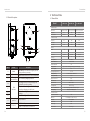
3.3 Product Description
D
G
H
F
E
A
B
C
Object
A
Charging
connection base
B
C
D
E
F
G
H
Description
Card swiping
position
LED
indicator
MODE SELECTION: Press to select certain mode.
Timer: When the light is on, the boost mode is
running.
Complete: When the light is on the EV-Charger
completes charging or is in idle state.
EMERGENCY STOP: Press in emergency, the EV-
Charger will stop operating.
Name
For connecting charging connector.
Operating status: The corresponding mode
light will be on when operating.
Fault: The red light will be on when error occurs.
Swipe card here.
Button
Switch
4 Technical Data
4.1 General Data
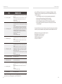
Model X1-EVC-7.2K X3-EVC-11K X3-EVC-22K
AC Nominal Input
Phases/Lines
Voltage [V ]
Frequency [Hz]
AC Nominal Output
Current [A]
Voltage [V ]
Power [VA]
Single Phase/L1+N+PE 3 Phase/L1+L2+L3+N+PE
230 400 400
50/60;±5
32 16 32
7200 11000 22000
Interface
RFID
RS485
LCD Screen
CT Clamps
YES
YES
Optional
x1
YES
YES
Optional
x3
YES
YES
Optional
x3
Housing Material
Installation Method
Wall-mount Bracket
Cable Length [M]
Operating Temperature [℃]
Working Humidity
YES
Wall-mounted
Plastic/Metal
6.5
-30~ +50
Working Altitude [M]
Degree of Protection
Application Site
Cooling Method
5%~95% without condensation
<2000
IP65
Indoor/Outdoor
Natural cooling
Protection Class Class I
3 Phase/L1+L2+L3+N+PE
50/60;±5 50/60;±5
Charging Outlet Type S(Socket-outlet)/Type P(Charging cable with plug)
Dimension (W*H*D)[mm]
Net Weight [kg]
249*370*155(for type S)/265*370*155(for type P)
7(for type S)/10.5(for type P)
Communication Info
EIRP Power
Frequency
Antenna Gain
Antenna Type
Wireless Mode
17.41 dBm(Measured Max. Average)
2412~2484 MHz
4 dBi
IPEX
802.11 b/g/n
WiFi
Communication Mode
230 400 400
1110
I
J
INPUT: For AC input connection.
COM: For communication connection.
IJ
Connector

Technical Data
4.2 Security Protection
30 mA Type A RCD (EN 61008) + 6 mA DC protection (EN 62955)
Integral Earth Leakage
Protection Integral
Safety Standard
Built-in PEN fault technology
Warranty
IEC61851-1; IEC62196-2
YES
3 years
Over/Under voltage protection
Model X1-EVC-7.2K X3-EVC-11K X3-EVC-22K
Multiple Protection
Overload protection
Short circuit protection
Current leakage protection
Grounding protection
Surge protection
Over/Under temperature protection
YES
YES
YES
YES
YES
YES
YES
BCD
A
I
E
5 Installation
5.1 Check for Transport Damage
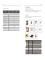
5.2 Packing List
Make sure the EV-Charger is intact during transportation. If there are some visible
damages, such as cracks, please contact your dealer immediately.
Open the package and fetch out the product, check the accessories at first. The
packing list is shown as below.
Object
EV-Charger
1
A
B
C
D
E
F
3/5
3/5
1
Expansion bolt (3 for type S, 5 for type P)
Self tapping screw (3 for type S, 5 for type P)
Manual
Quantity Description
European terminal
(3 for single-phase; 5 for three-phase)
3/5
1
CT (J1 for single-phase; J2 for three-phase)
G
K
G
J1
H
1
2
RJ45 terminal adapter
Cable hook (only for type P)
F
1Quick Installation Guide
I
EV-Charger 7.2 kW-22 kW
EV-Charger User Manual
7.2 kW - 22 kW
Copyright Declaration
The copyright of this manual belongs to SolaX Power Network Technology (Zhejiang) Co., Ltd.
Any corporation or individual should not plagiarize, partially or fully copy it (including
software, etc.), and no reproduction or distribution of it in any form or by any means shall be
allowed. All rights reserved. SolaX Power Network Technology (Zhejiang) Co., Ltd. reserves the
right of final interpretation.
H
3/5 Gasket (3 for type S, 5 for type P)
J
RFID card
J2
1
K
Installation
1312

Installation Installation
5.3 Installation Precaution
Available Space Size
The EV-charger is designed for wall-mounted installation (IP 65).
Make sure the installation site meets the following conditions:
· Not exposed to sunlight directly.
· Not in areas where highly flammable materials are stored.
· Not in potential explosive areas.
· Not near the television antenna or antenna cable.
· Not higher than altitude of about 2000 m above sea level.
· Not in environment of precipitation or humidity (5%~95%) .
· Make sure that the ventilation is good enough.
· The ambient temperature in the range of -30℃~ +50℃.
· The slope of the wall should be within ±5°.
Position Min.size
Ø
Left 300 mm
400-700 mm
200 mm
1.2-1.5 m
300 mm
Right
Top
Bottom
Front
Table: Available Space Size
The wall on which the EV-charger will be installed should meet the conditions below:
1) Solid brick/concrete, or strength equivalent mounting surface;
2) EV-charger must be supported or strengthened if the wall’s strength isn’t enough
(such as wooden wall, the wall covered by thick layer of decoration).
300 mm 400-700 mm
200 mm
1.2-1.5 m
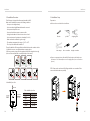
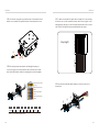
5.4 Installation Steps
STEP 1: Remove the screw from the EV-Charger with the cross screwdriver. Then
remove the back bracket away carefully.
No direct sunlight No Rain Exposure
No snow Lay up
Direct Sunlight Rain Exposure Snow Lay up Stay away from
antenna cables
Stay away from
combustibles
Preparation
Below tools are needed before installation.
Stripping pliers
Wire crimper Cross screwdriver Straight screwdriver
φ 8 drill
Prepare a communication cable with RJ45 and an input cable with outer
diameter of 12.5-18 mm(three-core for single-phase, ve-core for three-
phase).
●
●
Marker
1514

Installation Installation
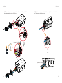
STEP 2: Fix the back bracket and the cable hook (only for type P) to the wall.
- Mark the position of the holes. - Insert the expansion bolts.
- Drill holes with φ 8 drill.
- Depth: at least 45 mm.
- Align the bracket and the cable hook (only
for type P) with the holes, and screw the self
tapping screws with the cross screwdriver.
STEP 3: Hang the EV-Charger on the wall for trial, then estimate the required length
of input cable and communication cable. After that, take the EV-Charger down.
STEP 4: Unscrew the EV-Charger’s rear cover with the cross screwdriver and take it
down. the fastening heads and take the waterproof materials away as Then undo
shown below.
(torque:1.5~2 N·m)
1716
≥400 mm

Installation Installation
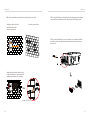
STEP 5: Unscrew the countersunk screw of the base plate of communication board
with the cross screwdriver. Then pull the base plate of communication board out .
STEP 6: Insert the prepared communication cable through the waterproof
connector in sequence as shown below (If the cable is self-made, also insert the
wires into the RJ45 terminals and then use crimping pliers to press them tightly).
1 2 3456 7 8
1) White with orange stripes
2) Orange
3) White with green stripes
4) Blue
5) White with blue stripes
6) Green
7) White with brown stripes
8) Brown
strip length
STEP 7: Strip the outer sheath of the input cable for a length of 60-70 mm, ensuring
all the wires can reach the terminal blocks with a little excessive length. Use the
stripping pliers to strip approx. 12 mm of insulation from the end of all the coloured
wires as below. Then crimp the European terminal with the wire crimper.
STEP 8: Insert the input cable through the waterproof connector in sequence as
shown below.
②
①L1 L2 L3
60-70 mm
60-70 mm
Outer Sheath
①
③
②
12 mm
①
③
②
PIN
Definition
1 2 3 4 5 6 7 8
A1
L1_CT+ B1
L1_CT- L3_CT+ L3_CT-L2_CT+ L2_CT-
* PIN 3, 6, 7, 8 is null for single-phase.
1918

Installation Installation
STEP 9: Insert the wires into the appropriate holes of the terminal blocks, then block
the terminals with the s .traight screwdriver
STEP 10: Press the spring upward and push the base plate of communication board
in. Then screw the countersunk screw.
<4 mm
(torque:1.5~1.8 N·m)
(torque:0.8~1.5 N·m)
L1
L2
L3
N
PE
2120

Installation Installation
STEP 11: Push the rear cover to appropriate position of the cables and screw the self
tapping screws with the cross screwdriver. Then tighten the waterproof fastening
head.
STEP 12: Hang the EV-Charger up carefully and steady the EV-Charger with the self
tapping screw and the cross screwdriver.
(torque: 2~2.5 N·m)
(torque: 2~2.5 N·m)
For type P, connect the charging connector with the EV-Charger and hang the
connecting cable on the hook.
2322

Installation Installation
grid EV-Charger
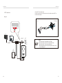
5.5 CT connection
L line
CT
Public grid
electricity
Notice: The arrow on the CT
must point at the public grid.
Diagram:
-Steay the CT on the public grid.
-Insert the other end of the communication cable and the terminal of CT on
each side of the adapter.
• Do not place the CT on the N Wire or the PE wire.
• Do not place the CT on the N and L wire simultaneously.
• Do not place the CT on the non-insulated wires.
• When using the three-phase CT please clip the CT clamps on the ,
corresponding phases.
NOTE!
Electrical
grid
other home Load
PV array
AC distribution box
Inverter
CT
Electricity meter,
bidirectional
2524

Operation Method Installation
5.6 Run the EV-Charger
a) Check that the device is xed well on the wall.
b) AC cable is connected to grid correctly.
Start EV-Charger after checking all below steps:
Start the EV-Charger
Check the status of LED indicators, the complete light should be on when the EV-
Charger starts normally.
If the complete light is not on, please check if it is correctly installed and connected
to the grid.
Ø
Ø
WARNING!
Power to the unit must be turned on only after installation work has
been completed. All electrical connections must be carried out by
qualied personnel in accordance with legislation in force in the
country concerned.
Equipment only to be used for the purpose outlined by SolaX.
NOTE!
6.1 States
Six states can be set for the EV-Charger, i.e. Idle, Stop, Charge, Complete, Fault
and Unavailable.
Indicator Light & Description
states
Idle
Charge
Complete
The Complete light is on and the MODE SELECTION button is invalid.
The connector is not inserted.
The corresponding charging mode light is on. The EV-Charger
is charging.
The Complete light and the STOP light are on at the same time.
The EV-Charger has completed charging and the MODE
SELECTION button is invalid.
Fault
Unavailable
The Fault light is on. The EV-Charger is in fault state.
The four charging mode lights are on at the same time.
The EV-Charger is remote upgrading.
Stop The STOP light is on. The EV-Charger is connected but not
charging.
The EV-Charger has two start-up patterns, namely plug & charge and card-
swiping pattern. The plug & charge pattern is the default pattern, and the card-
swiping pattern needs to “enable” the “RFID Function” in the APP advanced
settings.
1) Plug & charge pattern
For Socket Type, the electronic lock will be locked when the EV-Charger starts
charging and unlocked when the charging stops.
For Plug Type, there is no electronic lock.
2) Card-swiping pattern
For Socket Type, the electronic lock will be locked when the EV-Charger starts
charging after swiping the card, and unlocked after swiping the card when the
charging stops.
For Plug Type, there is no electronic lock.
Note:
The charging can be stopped from the vehicle end or the charger end (by long
pressing “MODE SELECTION” button, by APP setting or by swiping card). In
card-swiping pattern, the electronic lock will not unlock automatically when
the charging stops, and users need to swipe the card again to unlock it.
6 Operation Method
6.2 Start-up Patterns
2726

Operation Method Operation Method
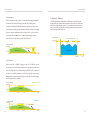
6.3.1 GREEN Mode
In GREEN Mode the EV-Charger will maximize the use of surplus power
generated from the inverter. According to the minimum start-up charging
power, the charging current can be divided into two levels as 3 A and 6 A. The
default level is 6 A.
In the 6 A level, the EV-Charger won’t use the power generated from grid at all.
In the 3 A level, the EV-Charger would start charging only when photovoltaic
power supply is more than 3 A. Meanwhile, if the photovoltaic power supply is
less than 6 A, the EV-Charger needs to buy extra electricity from grid for
minimum start-up charging power(1.4 kW for single-phase, 4.2 kW for three-
phase).
GREEN
ECO
FAST short press short press
GREEN/ECO/FAST STOP
Long press
Short press
short press
Short press the “MODE SELECTION” button, the charging mode will switch
among FAST, ECO and GREEN Modes.
Long press the “MODE SELECTION” button, the current charging mode will
switch to STOP mode. When the EV-Charger is in STOP mode, short press the
“MODE SELECTION” button, the EV-Charger will switch back to the previous
charging mode.(Only available in plug & charge pattern.)
Charging Power (kW)
Max. Power
Min. Power
GREEN mode (3A)
EN E RGY FR O M P V
EN E RGY FR O M G RID
Charging Power (kW)
Max. Power
EN E RGY FR O M P V
Min. Power
GREEN mode (6A)
6.3 Charging Modes
6.3.3 FAST mode
6.3.2 ECO mode
In FAST Mode, the EV-Charger will charge the EV at the fastest rate regardless
of whether the power generated by PV is sufficient and import grid electricity
if the power generated by PV is insufficient.
In ECO Mode, the charging power is continuously adjusted according to
changes in generation or power consumption elsewhere in the house, thereby
minimizing the use of grid power. In this mode, users can set charging current
at ve different levels, i.e. 6 A, 10 A, 16 A, 20 A and 25 A(only two levels for X3-
EVC-11K). If at any time, the available surplus power falls below the xed value
of power, such as 1.4 kW (4.2 kW for three-phase), the shortfall will be drawn
from the grid.
ECO mode (6/10/16/20/25 A)
Charging Power (kW)
Time
Max. Power
Min. Power
EN E RGY FRO M P V
EN E RGY FRO M G R ID
Charging Power (kW)
Max. Power
FAST mode
EN E R GY FRO M P V
EN E R GY FROM G R I D
2928

Operation Method Operation Method
6.3.4 Smart Boost
6.3.5 Timer Boost
Before using the Smart Boost function, set the desired charging energy(kWh)
and end time for the vehicle charging on the APP. The EV-Charger will
complete the charging of the EV with desired energy before the preset end
time at maximum charging power and will use the photovoltaic power supply
as much as possible and minimize the use of grid power. (E.g.: The user needs
to charge the EV to 40 kWh before 10:00 AM, then the Charging power is
depended on the surplus power generated by the inverter. )
When using ECO or GREEN charging modes, the E V- C harger can be
programmed to 'boost' the current charge in a certain period. In timer boost
mode, the charging rate is set to maximum (just like FAST mode), regardless of
the amount of available surplus power. This means that the power may be
drawn from the mains grid supply during boost times. If the EV is fully charged,
the EV-Charger will stop charging.
End Time
Charging Power (kW)
Time
Max. Power
Min. Power
EN E R G Y
FR O M
GR I D
EN E R G Y F R OM GRID
EN E R G Y F ROM PV
Start Time
Charging Power (kW)
Start Time Time
Max. Power
EN E R G Y F R OM PV
EN E R G Y F R OM GRID
End Time
Min. Power
GREEN mode (6 A)
Charging Power (kW)
Start Time Time
Max. Power
EN E R G Y F ROM PV
EN E R G Y F ROM GRID
End Time
Set Power
ECO mode
EN E R G Y F ROM GRID
6.4 Dynamic Load Balance
The EV-Charger has default dynamic load balancing function. During the
charging period, no matter in which work mode, the total power of the house
will not exceed the main grid capacity. To ensure the total power of the house
doesn’t exceed the grid capacity, the charging power will be adjusted in real
time following the total load power.
Charging Power (kW)
Time
Grid Capacity
Start Time
Other household load
The range of the charging power
End Time
3130

App SettingApp Setting
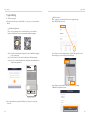
SolaXCloud Registration
Step 1: Use your smart phone to scan below QR code or search for the
keyword “SolaXCloud” in browser to download the Monitoring App.
IOS Google
Step 2: Touch the Setting button at upper left corner of the Monitoring App
to choose language.
Step 3: Touch “Create a new account” at the bottom of Monitoring App.
Step 4: Type in or scan the Registration No. and type in other information to
complete the registration.
(Registration No. example)
If you don't have the app or SolaX Cloud’s account yet,you can operate as
below:
If you already have the app and SolaX Cloud’s account, you can operate
as below:
●
●
7 App Setting
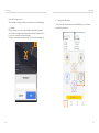
ØAPP account login
Step 3: Type in or scan the Registration No. of the EV-Charger. Then touch
Next and agree to join the network of the EV-Charger.
Step 4: Type in your home Wi-Fi SSID and password, then Setting.
*5GHz Wi-Fi is unavailable for now.
Wi-Fi Connection
Step 1: Login your account and turn to Account page in the app.
Step 2: Click “Wi-Fi Connection”.
3332
Nominal AC output apparent power 7200 VA
615.00184.01
Nominal AC input/output current 32 A a.c.
X1-EVC-7.2K(SXH)
Model:
SN:
50 Hz/60 Hz
Frequency
Nominal AC input/output voltage
Degree of protection IP65
Protection class
Ope ratin g temperature ran ge
I
230 V a.c.
-30℃~ +50℃
Connect io n Socket
Registration
No. :
SINGLE-PHASE
SMART EV CHARGER
SolaX Powe r Ne tw ork Tec hn ol og y (Zhejia ng ) Co ., L td .
www.solaxp ow er. com
L1+N+PE

App SettingApp Setting
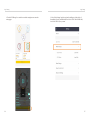
Step 5: Wi-Fi setting successes.
*Check more Wi-Fi setting information on www.solaxcloud.com/wiSetting/
Local Mode
Use your smart phone to connect the SolaX Wi-Fi signal (Wi_SCxxxxxxxx).
Then touch Local and type in password (initially same as the Registration No.)
to access the Local Mode in the Monitoring App.
*Visit the local password setting instruction on .solaxcloud.com/wiSetting/
ØSettings for the EV-Charger
1. Select “Site” at the bottom and then touch the “EV Charger” icon and select
your EV-Charger on the list.
3534

App SettingApp Setting
2. Touch the “EV Charger” icon and then touch the setting button to enter the
setting page.
3. Select “Mode Settings” and a drop-down list will appear. Set the levels of
Green Mode (2 levels) and ECO Mode(5 levels for X1-EVC-7.2K & X3-EVC-22K, 2
Levels for X3-EVC-11K) as you want.
3736
Page is loading ...
Page is loading ...
Page is loading ...
Page is loading ...
Page is loading ...
Page is loading ...
-
 1
1
-
 2
2
-
 3
3
-
 4
4
-
 5
5
-
 6
6
-
 7
7
-
 8
8
-
 9
9
-
 10
10
-
 11
11
-
 12
12
-
 13
13
-
 14
14
-
 15
15
-
 16
16
-
 17
17
-
 18
18
-
 19
19
-
 20
20
-
 21
21
-
 22
22
-
 23
23
-
 24
24
-
 25
25
-
 26
26


SoleX X3-EVC-11K EV Charger 7.2 kW – 22 kW User manual
- Type
- User manual
Ask a question and I''ll find the answer in the document
Finding information in a document is now easier with AI
Other documents
-
SolaX Power 7.2 kW – 22 kW EV Charger Installation guide
-
SolaX Power X1-X3-EVC Series Installation guide
-
 SolaX Power X3-EVC Series Installation guide
-
SolaX Power X1-G4 User guide
-
SolaX Power Pocket WiFi User manual
-
SolaX Power Pocket WiFi Interface V3.0 User manual
-
SolaX Power A1-G2 ESS User manual
-
SolaX Power DDSU666 User manual
-
SolaX Power DTSU666 User manual
-
FoxESS AC Charger User manual
