Page is loading ...

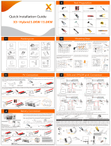
X3-MIC G2 Series 3 kW-15 kW
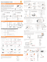
PV Connection
- Align the PV connectors.
cable size: 4 mm
strip length
Inverter X 1
AC connector X 1
Self tapping screw X 3
Documents LAN dongle (Optional)
WiFi dongle (Optional)
Expansion bolt X 3
Waterproof connector
with RJ45 X 1
Packing List
Inverter Installation
- Unscrew the bracket from the back of
the inverter.
- Screw the self tapping screws. - Match the inverter with the bracket.
- Screw the cross recessed screw on the
right side.
- Insert the expansion bolts.
positive DC
pin contact
male plug
negative DC
pin contact
clamp contact
nut female plug
tighten nut
cable
Inverter
PV array
PV1
PV2
+
-
+
-
+
-
+
-
+
-
Note!
The PV connection mode in this box
is not allowed!
×
Note: Please refer to the appropriate instruction manual for the
usage of WiFi and LAN dongle.
(torque:1.2±0.1 N·m)
Meter (Optional)
DC pin contact X 4/6
Earth terminal X 1
X1
- And mark the position(223 mm*30 mm)
of the three holes.
6
DC connector X 4/6
Round washer X 3
223
30
- Drill holes with φ10 drill.
- Depth: at least 60 mm.
torque: 0.8±0.1 N·m
X1
7 mm
cable
clamp contact
nut
tighten nut
2*positive, 2*negative for 3 kW-8 kW and 10 kW(input A: one string)
3*positive, 3*negative for 12 kW-15 kW and 10 kW(input A: two strings)
* For the optional accessories, please be subject to the actual delivery.

AC Connection WiFi Connection (Optional)
USB Connection (for upgrading)
- Screw the ground screw with the allen wrench shown as follows.
- Overview for connection.
Start inverter:
1. Turn on the external AC and DC connectors;
2. Turn on the DC switch to the “ON“ position;
3. Inverter will start automatically when PV
panels generate enough energy, the LED
will be blue.
320102040204
1. Slide the cable nut and back shell onto the cable.
2. Insert the stripped end of the five wires into the appropriate holes of the
male insert (The N wire and PE wire must be connected correctly), then
tighten each screw (Use the accompanying inner hexagon spanner).
5. Align the groove of male terminal with the convex of female terminal,
then tighten the bush in male terminal.
4. Tighten the screw of the back shell and the cable nut.
3. Tighten the screw of the back shell and the male insert.
1) Make sure the DC switch is
off and the AC is disconnected
with grid. Remove the WiFi
dongle module.
Update
ARM
DSP
2) Insert U-disk with upgrade
package* into the DONGLE port
on the bottom of the inverter.
Then turn on DC switch and
connect the PV connector, the
LCD will show a picture as on the
right.
3) Press “Up” and “Down” to select ARM or DSP. Then long press “Down” and select the correct update file to confirm the update. After the upgrade
is completed, please remember to turn off the DC switch or disconnect the PV connector, then pull off the U-disk, and connect the WiFi dongle
back.
* Please contact our service support to get the update package, and extract it into your U-disk.
Do not modify the program file name! Or it may cause the inverter to stop working!
Earth Connection and Overview
Ⅵ
Ⅶ
strip length
L1
L2
L3
Select appropriate cable according to the power range as
recommended in “Table: Cable and Micro-breaker
recommended” of the manual and strip the wires as below.
Note:
- This inverter provides a monitoring dongle connecting port (the DONGLE port) which can collect information
from inverter including status, performance and updating information to the monitoring website via connecting
WiFi/LAN/4G dongle (The monitoring dongle is optional, which can be purchased from the supplier if needed).
- For example, plug the WiFi dongle into the port named “DONGLE” on bottom of the inverter.
torque: 1.2±0.1 N·m
55 mm
52.5 mm
12 mm
For details on the usage of WiFi and other monitoring dongles, please refer to the corresponding instruction manuals.
/