Page is loading ...

描述
材料
料号
单位 页次
设计
审核
核准
技术要求:
1.封面封底157g铜版纸覆哑膜彩打,内部纸80g双胶纸黑白印刷,正反打印
2.装订方式:页码大于60需用胶装
3.未注尺寸公差按 +- 1.5mm
4.图面、字体印刷清晰、无偏移/无毛边、不起边、油墨不脱落
5.字体颜色为PANTONE Black C,无边框,底色为白色
6.符合RoHS要求
X1-Retro Fit Series说明书
614.00204.01浙江艾罗电源有限公司
夏 炅 2017/7/18
朱娴红 2017/7/18
朱娴红 2017/7/18
NA
REV. REV.
Description Description
0.0
首次发行
夏炅 2017/7/18
描述
料号
单位 页次
浙江艾罗电源有限公司
SolaX Power Co.,Ltd.
Q-OP-SC-01-02 V1.0
285.00 mm
210.00 mm
X1-Retro Fit Series说明书
614.00204.01
0.0
夏炅 2017/7/27
A 修改相对湿度参数和尺寸、AC和EPS接线端
口,增加Off Mode、参数单位,修正语法错误。
0.0
夏炅 2017/8/1
B 修改技术要求:装订方式
0.0
夏炅 2017/8/3
C 增加发电机控制接口内容
0.1
夏炅 2017/10/12
修改BMS&Meter接线步骤和结构图;增加公司新名称;修改DSP/ARM烧
录顺序DSP升级路径等其他信息;修改LCD Operation

Copyright Declaration
X1-Retro Fit User Manual
3.7kw - 5.0kw
614.00204.01
Solax Power Network Technology(Zhe jiang) Co,. Ltd.
(Solax Power Co,. Ltd) The copyright of this manual belongs to Solax Power Network Technology(Zhe jiang) Co,. Ltd.
(SolaX Power Co.,Ltd.). Any corporation or individual should not plagiarize, partitially or fully
copy (including software,etc.), and no reproduction or distribution of it in any form or by any
means. All rights reserved. SolaX Power Network Technology (Zhe jiang) Co.,Ltd. (SolaX Power
Co.,Ltd.). reserves the right of final interpretation.

Contents
Contents
1 Note on this Manual
1.1 Scope of Validity
1.2 Target Group
1.3 Symbols Used
2 Safety
2.1 Important Safety Instructions
2.2 Explanation of Symbols
2.3 EC Directives
3 Introduction
3.1 Basic Features
tus 3.2 Work Sta
3.3 Dimension
3.4 Terminals of Inverter
4 Technical Data
4.5 General Data ( apply to version E, I, C )
4.4 EPS output ( apply to version E, I )
4.3 Efficiency, Safety and Protection ( apply to version E, I,C )
4.2 Internal Charger ( apply to version E, I, C )
4.1 AC output/input ( apply to version E, I, C )
5.3 Mounting
5.1 Check for Transport Damage
5.2 Packing List
5. Installation
03
03
03
03
04
04
08
09
10
10
12
13
14
15
17
16
16
15
15
19
18
18
18
6 Electrical Connection
6.1 Grid Connection
6.2 EPS Connection( apply to I Version and E Version)
6.3 Battery Connection
6.4 Earth Connection
22
22
24
28
31
01

1.1 Scope of Validity
This manual is an integral part of X1-Retro Fit, It describes the assembly,
installation, commissioning, maintenance and failure of the product. Please read it
carefully before operating.
Note: “3.7” means 3.7kW.
“E” means “EPS function” will be available with an external changeover
device installed.
“I” means “EPS function” available as unit already content an internal
changeover device.
“C “means without”EPS function”.
Store this manual where it will be accessible at all times.
1.2 Target Group
This manual is for qualified electricians. The tasks described in this manual only
can be performed by qualified electricians.
1.3 Symbols Used
The following types of safety instructions and general information appear in this
document as described below:
1 Notes on this Manual
Notes on this ManualContents
Danger!
“Danger” indicates a hazardous situation which, if not avoided, will result in
death or serious injury.
Warning!
“Warning” indicates a hazardous situation which, if not avoided, could result
in death or serious injury.
Caution!
“Caution” indicates a hazardous situation which, if not avoided, could result
in minor or moderate injury.
Note!
“Note” provides tips that are valuable for the optimal operation of our
product.
X1-Fit-3.7E
X1-Fit-3.7I
X1-Fit-3.7C
X1-Fit-4.6E
X1-Fit-4.6I
X1-Fit-4.6C
X1-Fit-5.0I
X1-Fit-5.0E
X1-Fit-5.0C
03
8. Setting
8.1 Control Panel
8.2 Menu Structure
8.3 LCD Operation
9 Troubleshooting
9.1 Trouble Shooting
9.2 Routine Maintenance
10 Decommissioning
Dismantling the Inverter10.1
Packaging10.2
Storage and Transportation10.3
42
42
43
44
6.5 Meter Connection
6.6 LAN Connection
6.7 DRM Connection
6.8 WiFi Connection(optional)
6.9 RF Connection(optional)
6.10 Inverter Manipulation
32
34
35
36
37
38
7. Firmware Upgrading 40
62
62
66
67
67
67
67
02

2 Safety
SafetySafety
2.1 Important Safety Instructions
Danger!
Danger to life due to high voltages in the inverter!
All work must be carried out by qualified electrician.
The appliance is not to be used by children or persons with
reduced physical sensory or mental capabilities, or lack of
experience and knowledge, unless they have been given
supervision or instruction.
Children should be supervised to ensure that they do not play
with the appliance.
Caution!
Danger of burn injuries due to hot enclosure parts!
During operation, the upper lid of the enclosure and the enclosure
body may become hot.
Only touch the lower enclosure lid during operation.
Caution!
Possible damage to health as a result of the effects of radiation!
Do not stay closer than 20 cm to inverter for any length of time.
Warning!
Authorized service personnel must disconnect AC power from
inverter before attempting any maintenance or cleaning or
working on any circuits connected to inverter.
Prior to the application, please read this section carefully to ensure correct and
safe application. Please keep the user manual properly.
Accesories only together with the inverter shipment are recommanded here.
Otherwise may result in a risk of fire, electric shock, or injury to person.
Make sure that existing wiring is in good condition and that wire is not
undersized.
Do not disassemble any parts of inverter which are not mentioned in
installation guide. It contains no user-serviceable parts. See Warranty for
instructions on obtaining service. Attempting to service the inverter yourself
may result in a risk of electric shock or fire and will void your warranty.
Keep away from flammable, explosive materials to avoid fire disaster.
The installation place should be away from humid or corrosive substance.
Authorized service personnel must use insulated tools when installing or
working with this equipment.
The unit contains capacitors that remain charged to a potentially lethal voltage
after the MAINS battery has been disconnected.and
Hazardous voltage will present for up to 5 minutes after disconnection from
power supply.
CAUTION-RISK of electric shock from energy stored in capacitor, Never operate
on the inverter couplers, the MAINS cables or Battery cables when power is
applied. After switching off the battery and Mains, always wait for 5minutes to
let the intermediate circuit capacitors discharge before unpluging battery
inplug and MAINS couplers.
When accessing the internal circuit of inverter, it is very important to wait 5
minutes before operating the power circuit or demounting the electrolyte
capacitors inside the device. Do not open the device before hand since the
capacitors time to sufficiently discharge! require
Measure the voltage between terminals UDC+ and UDC- with a multi-meter
(impedance at least 1Mohm) to ensure that the device is discharged before
beginning work (35VDC) inside the device.
Lightning will cause a damage either from a direct strike or from surges due to
a nearby strike.
Specialists in lightning protection should be consulted during the end use
application.
Using appropriate external lightning protection, the effect of a direct lightning
strike into a building can be mitigated in a controlled way, and the lightning
current can be discharged into the ground.
Installation of SPDs to protect the inverter against mechanical damage and
excessive stress include a surge arrester in case of a building with external
lightning protection system (LPS) when separation distance is kept.
04 05
Do not operate the inverter when the device is running.
WARNING !
Risk of electric shock!
WARNING !

Anti-Islanding Effect
►
• Islanding effect is a special phenomenon that grid-connected system still
supply power to the nearby grid when the voltage loss is happened in the
power system. It is dangerous for maintenance personnel and the public.
• X1-Retro Fit series inverter provide Active Frequency Drift(AFD) to prevent
islanding effect.
PE Connection and Leakage Current
High leakage current!
Earth connection essential before connecting supply.
WARNING !
►
SafetySafety
06 07
To protect the AC system, surge suppression devices (SPD type2) should be
fitted at the main incoming point of AC supply (at the consumer’s cutout),
located between the inverter and the meter/distribution system; SPD (test
impulse D1) for signal line according to EN 61632-1.
• The end-use application shall monitor the protective conductor by residual
current operated protective device (RCD) with rated fault current Ifn≤240mA
which automatically disconnects the device in case of a fault.
For United Kingdom
• The installation that connects the equipment to the supply terminals shall
comply with the requirements of BS 7671.
• No protection settings can be altered.
• User shall ensure that equipment is so installed, designed and operated to
maintain at all times compliance with the requirements of ESQCR22(1)(a).
For Australia and New Zealand
• Electrical installation and maintenance shall be conducted by licensed
electrician and shall comply with Australia National Wiring Rules.
• Incorrect grounding can cause physical injury, death or equipment
malfunction and increase electromagnetic.
• Make sure that grounding conductor is adequately sized as required by
safety regulations.
• Do not connect the ground terminals of the unit in series in case of a
multiple installation. This product can cause current with a d.c component,
where a residual current operated protective (RCD) or monitoring (RCM)
device is used for protection in case of direct or indirect contact, only an
RCD or RCM of type B is allowed on the supply side of this product.
Battery Safety Instructions
►
SolaX X1-Retro Fit series inverter should be worked with high voltage battery,
for the specific parameters such as battery type, nominal voltage and nominal
capacity etc., please refer to section 4.2.
As accumulator batteries may contain potential electric shock and short-circuit
current danger, to avoid accidents that might be thus resulted, the following
warnings should be observed during battery replacement:
1: Do not wear watches, rings or similar metallic items.
2: Use insulated tools.
3: Put on rubber shoes and gloves.
4: Do not place metallic tools and similar metallic parts on the batteries.
5: Switch off load connected to the batteries before dismantling battery
connection terminals.
6: Only personal with proper expertise can carry out the maintenance of
accumulator batteries.

2.2 Explanation of Symbols
This section gives an explanation of all the symbols shown on the inverter and
on the type label.
Symbols on the Inverter
Symbol Explanation
Operating Display.
Battery communication is active.
An error has occurred, please inform your installer immediately.
Symbols on the Type Label
Symbol Explanation
CE mark.
The inverter complies with the requirements of the applicable
CE guildlines.
TUV certified.
RCM remark.
SAA certification.
Beware of hot surface.
The inverter can become hot during operation. Avoid contact
during operation.
Danger of high voltages.
Danger to life due to high voltages in the inverter!
Danger.
Risk of electric shock!
Observe enclosed documentation.
08
The inverter can not be disposed together with the household waste.
Disposal information can be found in the enclosed documentation.
Do not operate this inverter until it is isolated from battery and mains
Danger to life due to high voltage.
• There is residual voltage existing in the inverter after powering off,
which needs 5 min to discharge.
• Wait 5 min before you open the upper lid.
This chapter follows the requirements of the European low voltage
directives, which contains the safety instructions and conditions of
acceptability for the endues system, which you must follow when installing,
operating and servicing the unit. If ignored, physical injury or death may
follow, or damage may occur to the unit. Read this instructions before you
work on the unit. If you are unable to understand the dangers, warnings,
cautions or instructions, please contact an authorized service dealer before
installing. Operating and servicing the unit.
The Grid connected inverter meets the requirement stipulated in Low Voltage
Directive (LVD) 2014/35/EU and Electromagnetic Compatibility (EMC) Directive
2014/30/EU. The unit is based on:
EN 62109-1:2010 ; EN 62109-2:2011 ; IEC 62109-1(ed.1) ; IEC62109-2(ed.1)
EN 61000-6-3:2007+A:2011 ; EN 61000-6-1:2007 ; EN 61000-6-2:2005 ; EN 62477
The grid connected inverter leave the factory completely connecting device and
ready for connection to the mains,the unit shall be installed in accordance with
national wiring regulations. Compliance with safety regulations depends upon
installing and configuring system correctly, including using the specified wires.
The system must be installed only by professional assemblers who are familiar
with requirements for safety and EMC. The assembler is responsible for ensuring
that the end system complies with all the relevant laws in the country where it is
to be used.
The individual subassembly of the system shall be interconnected by means of
the wiring methods outlined in national/international such as the national electric
code (NFPA) No.70 or VDE regulation 0107.
2.3 CE Directives
09
Safety Safety

3. Introduction
10 11
Introduction Introduction
3.1 Basic features
X1- Series is a high-quality inverter which can store energy into battery.Retro Fit
The inverter can be used to optimize self consumption, store in the battery for
future use or feed-in to public grid. Work mode depends on the battery and user’s
preference. It can provide power for emergency use during the grid lost by using
the energy from battery.
System Diagram
►
X1-Retro Fit Series is designed with two EPS versions for customer to choose
based on the local rules.
E Version applies to the wiring rules requires the Live line and Neutral line of that
E must with the Live line and Neutral line of gridPS be disconnected . (applies to
most countires)
SolaX
meter +
-
Battery
DPDT
E-BAR
Main switch
RCD RCD
PE
EPS
Load
Inverter
I Version applies to the wiring rules that requires Neutral line of alternative supply
must NOT be isolated or switched (applies to wiring rules AS/NZS_3000:2012 for
Australia and New Zealand).
SolaX
meter +
-
Battery
E-BAR
Main switch
RCD RCD
EPS
Loads
Inverter
Loads
Note!
Please control the home loads, and make sure it’s within the “EPS
output rating” under EPS mode, otherwise the inverter will shutdown
with an “overlaod fault” warning.
Please confirm with the mains grid operator whether there is any
special regulations for grid connection.
•
•
E-BAR

Introduction Introduction
12 13
3.2 Work Modes
·In the absence of the external generator, or
the power is not enough,battery will
discharge for local loads firstly, and grid will
supply power when the battery capacity is
not enough.
EPS Status
When the grid is off, system will supply
emergency power from battery to supply the
home loads. (Battery is necessary in EPS mode.)
X1-Retro Fit Series inverter provides multiple work modes based on different
requirements.
Work modes: Feed in Priority
Priority:load>grid>battery
This mode applies the area that has high feed-in
tariff and export control.
Work modes: Back up mode
Priority:battery>load>grid
This mode applies the area that has frequent
power outages. And this mode ensures the battery
will has enough energy to supply when the grid is
off.
Work modes: Self-use
Priority: load>battery>grid
This mode applies the area that has low feed-in
tariff and high energy price.
Work modes: Force time use
Priority:battery>load>grid(when charging)
Priority:load>battery>grid(when discharg-
ing)
This mode applies the area that has electricity
price between peak and valley. User can use off-
peak electricity to charge the battery.
·In the case of the external generator, the
power generated will be used to supply the
local loads firstly, then to charge the battery.
The redundant power will export to the
public grid.
·The charging and discharging time can be
set flexibly.
3.3 Dimension
464.0mm
476.0 mm
180.0 mm
·In the case of the external generator, the
power generated will be used to supply the
local loads firstly, then export to the public
grid. The redundant power will charge the
battery.
·In the absence of the external generator, or
the power is not enough,battery will discharge
for local loads firstly, and grid will supply power
when the battery capacity and power
generation is not enough.
·In the case of external power generation
equipment, the power generated will be used
to charge the battery fully firstly, then supply
the local loads. The redundant power will
export to the public grid.
·In the absence of an external power
generation device, charge the battery with the
public grid.
·The inverter will switch to EPS mode only
when the grid is abnormal.

4. Technical Data
Norminal AC power[ VA]
Max. apparent AC power[VA]
Rated grid voltage(range)[V]
Rated grid frequency[Hz]
Norminal AC current[A]
Max.AC current[A]
Displacement power factor
Total harmonic distortion( THDi)
Parallel operation
Load control
X1-Fit-3.7E
Model
3680
3680
16
16
4600
4600
20
21
4999
4999
21.7
21.7
AC output
220/230/240 VAC(180 to 270 VAC)
50/60
0.8 leading...0.8 lagging
< 2%
Being developed
Being developed(optional)
AC input
Norminal power[ ]AC VA (E&C Version)
Norminal AC power[ VA](I Version)
Rated grid voltage(range)[V]
Rated grid frequency[Hz]
Max. current[A]AC (E&C Version)
Max. AC current[A](I Version)
Displacement power factor
Norminal AC current[A](E&C Version)
Norminal AC current[A](I Version)
AC inrush current[A]
AC maximum output fault current[A]
3680
16
16+21.7(bypass)
4600
21
21+26.0(bypass)
4999
21.7
21.7+26.0(bypass)
220/230/240 VAC (180 to 270 VAC)
50/60
0.8 leading...0.8 lagging
Introduction Technical Data
14 15
Object
A
B
C
D
E
F
G
H
I
J
K
Battery connection area
EPS output
Grid output
WiFi port for external Pocket WiFi
Waterproof valve
Earthing screw
CAN communication port for parallel operation/
Generator communication port
(Both functions are being developed.)
Ethernet port / DRM port
Battery communication / External meter port
External port for smart plug
USB port for upgrading
Description
Qualified electrician will be required for the installation.
WARNING !
3.4 Terminals of PV inverter
ABC D E
FG A
I
H
AK
J
3680+4000(bypass) 4600+5000(bypass) 4999+5000(bypass)
X1-Fit-3.7I
X1-Fit-3.7C
X1-Fit-4.6E
X1-Fit-4.6I
X1-Fit-4.6C
X1-Fit-5.0E
X1-Fit-5.0I
X1-Fit-5.0C
4.1 AC output/input ( apply to version E, I,C )
4.2 Internal Charger ( apply to version E, I,C )
Model X1-Fit-3.7C X1-Fit-4.6C
X1-Fit-3.7E
X1-Fit-3.7I
X1-Fit-4.6E
X1-Fit-4.6I X1-Fit-5.0E
X1-Fit-5.0I
X1-Fit-5.0C
16
16+17.4(by pass)
20
20+17.4(by pass)
21.7
21.7+17.4(by pass)
EPS
CAN /GE N
LAN /DR M
Gri d
WiF i
RF
BMS/M eter
Upg rad e
+
PV1 P V2 B AT
+ +
- - -
ON
OFF
35 35 35
80 80 80
Battery type
Battery voltage range[V ]
Recommended battery voltage[V ]
Recommended battery capacity[KWh]
Max. charge/discharge current[A]
Peak charge/discharge current[A]
Communication interfaces
Reverse connect protection
Lithium battery
85-400
300VDC
4.8-16.8
20A(adjustable)
30A, 30s
CAN/RS485
Yes

16
17
Technical Data
4.4 EPS output ( apply to version E, I )
EPS rated power[ VA]
Max. EPS power[VA]
EPS rated voltage[v], Frequency[Hz]
EPS rated current[A]
Max. EPS current[A]
EPS peak power[ W]
Switch time[s]
Total harmonic distortion( THDv)
Parallel operation
Changeover device(E Version)
Changeover device(I Version)
Compatible with the generator
Model
4000
5000
17.4
21.7
5000
6000
21.7
26.0
5000
6000
21.7
26.0
230VAC, 50/60
<500ms
<2%
Being developed
external
internal
Being developed
YES
YES
YES
YES
YES
YES
YES
YES
YES
4.3 Efficiency, Safety and Protection ( apply to version E, I,C )
Model
Safety & Protection
Over/under voltage protection
DC isolation protection
Monitoring ground fault protection
Grid protection
DC injection monitoring
Residual current detection
Anti-islanding protection
Over load protection
Over heat protection
95.60% 95.60% 95.60%
4.5General Data ( apply to version E, I, C )
Operating temperature range[ ]℃
Storage temperature [ ]℃
Storage/Operation relative humidity
Altitude [m]
Ingress Protection
Protective Class
Over Voltage Category
Cooling
Noise emission(typical)
Inverter Topology
Communication interface
LCD display
Installation
Night-time consumption
Pollution Degree
Model
-20~+60 (derating at 45)
-20~+60
4%~100% (Condensing)
<2000
IP65
Ⅰ
III(electric supply side), II(battery side)
Nautral
<40dB
Transformerless
Ethernet, Meter, WIFI(optional), RF(optional), DRM, USB, ISO alarm
Backlight 20*4 character
Wall-mounted
<3W
III
Technical Data
Max. Battery charge efficiency
AC to BAT )(@full load)
Max. Battery discharge efficiency
(BAT to AC)(@full load) 97.00% 97.00% 97.00%
X1-Fit-3.7E
X1-Fit-3.7I
X1-Fit-4.6E
X1-Fit-4.6I
X1-Fit-5.0E
X1-Fit-5.0I
X1-Fit-3.7E
X1-Fit-3.7I
X1-Fit-3.7C
X1-Fit-4.6E
X1-Fit-4.6I
X1-Fit-4.6C
X1-Fit-5.0E
X1-Fit-5.0I
X1-Fit-5.0C X1-Fit-3.7C X1-Fit-4.6C
X1-Fit-3.7E
X1-Fit-3.7I X1-Fit-4.6E
X1-Fit-4.6I X1-Fit-5.0E
X1-Fit-5.0I
X1-Fit-5.0C
Dimension [W/H/D](mm)
Dimension of packing [W/H/D](mm)
Net weight [kg]
Gross weight [kg]
23
476*464*180
600*540*350
26
Max. efficiency 97.00% 97.00% 97.00%
8000,10s6000,10s

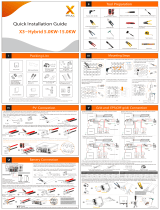
5. Installation
5.1 Check for Physical Damage
5.2 Packing List
Make sure the inverter is intact during transportation. If there is any visible
damage, such as cracks, please contact your dealer immediately.
Open the package and take out the product, please check the accessories first.
The packing list shown as below.
Installation Installation
Object
A
B
C
D
E
F
Inverter
Bracket
Expansion tubes & Expansion screws
Battery connectors (1*positive, 1*negative)
Description
Object
G
H
I
J
K
L
Quick installation guide
Description
Installation Precaution
X1-Retro Fit Series inverter is designed for outdoor installation (IP 65).
Make sure the installation site meets the following conditions:
Not in direct sunlight.
Not in areas where highly flammable materials are stored.
Not in potential explosive areas.
Not in the cool air directly.
Not near the television antenna or antenna cable.
Not higher than altitude of about 2000m above sea level.
Not in environment of precipitation or humidity (>95%).
Under good ventilation condition.
The ambient temperature in the range of -20℃ to +60℃.
The slope of the wall should be within ±5°.
The wall hanging the inverter should meet conditions below:
1.solid brick/concrete, or strength equivalent mounting surface;
2.Inverter must be supported or strengthened if the wall’s strength isn’t
enough(such as wooden wall, the wall covered by thick layer of decoration)
Please AVOIDE direct sunlight, rain exposure, snow laying up during installation
and operation.
A
5.3 Mounting
B C D
EK L
18
19
M
M
Warranty card
4 6AWG AC terminals and 4 10AWG AC terminals for Version I
8 10AWG AC terminals for Version E and Version C
Version I Version E&C
N
N O P
O
Meter
Smart Plug (optional)
Wifi module (optional)
F I J
HG
Ring terminal(for external enclosure grounding)
Set screw( for mounting)
Grounding nut
gasket( for using thin cable to connect on the AC port)
Ring terminal(for internal enclosure grounding)
User manual
P

Space Requirement
Position Min.size
Ø
300mm 300mm Left 300mm
300mm
300mm
300mm
300mm
Right
Top
Bottom
Front
Table Available Space Size
300mm
300mm
Installation Installation
Mounting Steps
Ø
Step 1: Screw the wall bracket on the wall
Tools required for installation.
1.1 Place the bracket on the wall and mark down the position of the 4 holes.
1.2 Drill holes with driller, make sure the holes are deep enough (at least 60mm) to
support the inverter.
1.3 Install the expansion tubes in the holes, and tighten them. Then install the wall
bracket with the expansion screws.
Installation tools : crimping pliers for binding post and RJ 45, screwdriver,
manual wrench and
Step 1
Step 2
Overview of Mounting
Step 2: Place the inverter on the wall mounted bracket by holding the handle on
the side.
375 . 0 m m
263 . 0 m m
20
21
Step 3
Step 4
Step 3: Screw the set screw on the left-bottom of inverter tightly.
Step 4: If necessary, costomer can install an anti-theft lock on the left-bottom of
the inverter.

6.1 Grid Connection
X1-Retro Fit series inverter are designed for single phase grid. Voltage is
220/230/240V, frequency is 50/60Hz. Other technical requests should comply
with the requirement of the local public grid.
Micro-breaker should be installed between inverter and grid, any load should
not be connected with inverter directly.
Table 4 Cable and Micro-breaker recommended
Connection Steps:
Step1. Check the grid voltage.
1.1 Check the grid voltage and compare with the permissive voltage range (Please refer to
technical data).
1.2 Disconnect the circuit-bricker from all the phases and secure against re-connection.
Step2. Remove the top-down cover from the inverter.
Step3. Make AC wires.
3.1 Choose the appropriate wire(Cable size: refer to Table 4).
3.2 Reserve about 60mm of conductor material sectional area.
3.3 Remove 12mm of insulation from the end of wire.
3.4 Insert stripped wires into AC terminal and insure all conductor strands are captured in the AC
terminal.
3.5 Compress the AC terminal head by using a crimping pliers and screw down screw cap tightly.
Step4. Insert AC cable into Grid port through screw cap and then tighten the
screw cap. Insert L wire and N wire into corresponding ports of AC terminal.
Compress the PE wire with earth terminal , then screw it on the grounding stud.
Cable
Micro-breaker
4-5mm²5-6mm²5-6mm²
20A 32A 32A
Model
Cable Inverter+BMU
Micro-breaker
8-10mm²10-13mm²10-13mm²
50A 63A 63A
E Version & C Version
I Version
Electrical ConnectionElectrical Connection
22
6. Electrical Connection
X1-Fit-3.7E
X1-Fit-3.7I
X1-Fit-3.7C
X1-Fit-4.6E
X1-Fit-4.6I
X1-Fit-4.6C
X1-Fit-5.0E
X1-Fit-5.0I
X1-Fit-5.0C
PE wire connection
L-wire,N-wire connection
Insert AC cable into Grid port
through screw cap
Cable Size: Refer to Tabel 4(page 24)
Step2.
Step3.
Step4.
X N L
60mm
12mm
23
I N L
Note: No need toconn-
ect wire on X port by
enduser!
I Version
E Version
Note:I port has been
wired during the
manufactory.

6.2 EPS Connection( apply to I Version and E Version only)
X1-Retro Fit series inverter has On and Off grid function, the inverter will deliver
output power through AC port when the grid is on, and it will deliver output
power through EPS port when the the grid is off.
I Version & E Version
Ø
Auto & Manual
Ø
X1-Retro Fit series inverter provides two versions for customer to choose based
on the local rules.
“I Version” means inverter has an build-in changeover switch. This version applies
to the wiring rules which requires Neutral line of alternative supply must not be
isolated or switched.(applies to wiring rules AS/NZS3000:2014 of Australia and
New Zealand.)
“E Version” means inverter needs to install an external changeover device for EPS
function. This version applies to the wiring rules which allows Neutral line of
alternative supply can be isolated or switched.( applies to most of the countries)
EPS function can be achieved automatically or manually according to user’s wishes.
For “I Version” inverter, EPS function can only be triggered automatically.
For “E Version” inverter, EPS function can be triggered either automatically or
manually according to user’s preference.
If user wants to use this function manually, it will need to be installed an external
switch. Please refer to specific wiring diagram below.
For automatical solution, please contact our sales.
+
-
Battery
E-BAR
PE
N-BAR
RCD
EPS Load
L L
I Version
RCD
Load
RCMB
L
L
N
I Version Auto Do not required for Changeover Switch
EPS AC
EPS breaker: refer to
Table 5(page 28)
RCD: type A
wired by manufactor
required for installation
+
-
Battery
E-BAR
PE
RCD
EPS Load
L L
E Version
RCD
Load
RCMB
L
L
N
E Version Manual Required for Changeover Switch
AC
RCD: type A
wired by manufactor
required for installation
EPS
changeover device( DPDT)
+
-
Battery
E-BAR
PE
RCD
EPS Load
L L
E Version
RCD
Load
RCMB
L
L
N
E Version Auto Required for Changeover Switch
AC
RCD: type A
wired by manufactor
required for installation
EPS
Contactor Device
Contactor
Please contact our sales for any compatible contactor purchase requirement .
Note!
In case of discrepancies between wiring mode of local policy and
the operation guide above, especially for the wiring of neutral line,
grounding and RCD, please contact us before any operation!
Electrical ConnectionElectrical Connection
24
25
EPS breaker: refer to
Table 5(page 28)
EPS breaker: refer to
Table 5(page 28)
I I
PE
PE

Connection Steps:
60mm
12mm
60mm
12mm
I Version
Step1.Make EPS wires.
3.1 Choose the appropriate wire(cable size: refer to picture below).
3.2 Reserve about 60mm of conductor material sectional area.
3.3 Remove 12mm of insulation from the end of wire.
3.4 Insert stripped wires into AC terminal and insure all conductor strands are captured in
the AC terminal.
3.5 Compress the AC terminal head by using a crimping pliers and screw down screw cap tightly.
Step2. Insert EPS cable into EPS port through screw cap and then tighten the
screw cap. Insert L wire, N wire and PE wire( PE wire applies to E Version only)
into corresponding ports of EPS terminal and screw them tightenly.
Step2.
L N PE
I Version
E Version
Note: Connect PE wire into
PE port!
Note: The black cable( the I port )
has been wired during the
manufactory.
Step1.
ØRequirements for EPS loadØ
Make sure the EPS load power rating is within EPS output rating,
otherwise the inverter will shutdown with an “over load” warning.
When an “over load” is appeared, adjust the load power to make
sure it is within the EPS output power range, then turn the inverter
back on.
For the nonlinear load, please make sure the inrush power should
be within the EPS output power range.
WARNING !
Below table shows some common feasible loads for you reference.
Type Power
Start Rated
Common
equipment
Example
Resistive
load
Inductive
load
Capacitive
load
X 1
X 2
X 1
X 1.5
X 3~5 X 2
Start Rated
100VA
(W)
100VA
(W)
80VA
(W)
60VA
(W)
450-750VA
(W)
300VA
(W)
Equipment
Fluorescent lamp Fluorescent lamp
40W
Fan Fridge Fridge
150W
Incandescent
lamp
TV Incandescent
lamp
100W
L N I
Electrical ConnectionElectrical Connection
26
27
E Version
Table 5 Cable and Micro-breaker recommended
EPS Cable
EPS breaker
≥5mm² ≥5mm² ≥5mm²
25A 32A 32A
Model X1-Fit-3.7E
X1-Fit-3.7I
X1-Fit-3.7C
X1-Fit-4.6E
X1-Fit-4.6I
X1-Fit-4.6C
X1-Fit-5.0E
X1-Fit-5.0I
X1-Fit-5.0C

6.3 Battery Connection
Charging & discharging system of X1-Retro Fit series inverter is designed for
high-voltage lithium battery.
Before choosing battery, please note the maximum voltage of battery can not
exceed 400V and the rated voltage of battery can not exceed 350V, and the
battery communication should be compatible with X1-Retro Fit inverter.
Before connecting to battey, please install a nonpolarized breaker to make sure DC
inverter can be securely disconnected during maintanance.
Battery breakerØ
Voltage
Current[A] 32A
Model
Nominal voltage of DC breaker should be larger than maximum
voltage of battery.
Battery connection diagramØ
Power Connection Steps:
Ø
Step2. Insert the stripped cable up to the stop ( negative cable for DC plug(-) and
positive cable for DC socket(+) are live). Hold the housing on the screw
connection.
Step3. Press down spring until it clicks audibly into place.(it must be possible to
see the fine wire strands in the chamber)
Step1. Choose the 9 AWG wire and strip the cable to 15mm.
high-voltage lithium battery.
+
-
CAN/ RS485
Nonpolarized
DC breaker
Power connection
Communication connection
Communication interface bewteen inverter and battery is RS485 or CAN with a
RJ45 connector.
BMS PIN DefinitionØ
Note!
The battery communication can only work when the battery BMS is
compatible with the inverter.
DC plug housing(-) DC socket housing(+)
screw connection
screw connection
spring
chamber
wire strands
Step4. Tighten the screw connection(tighten torque:2.0Nm)
Note: BAT port, not PV port!
Note: The positive line and negative line are not allowed to access anti-Line.
Electrical ConnectionElectrical Connection
Step5. Plug the PV conntector into the corresponding PV connector on inverter.
Step2.
Step3.Step 4.
Step5.
28
29
X1-Fit-3.7E
X1-Fit-3.7I
X1-Fit-3.7C
X1-Fit-4.6E
X1-Fit-4.6I
X1-Fit-4.6C
X1-Fit-5.0E
X1-Fit-5.0I
X1-Fit-5.0C
1
8
BMS_CANH
GNDX X BMS_CANL
Definition
23 4 56 7 81
PIN
BMS_485A BMS_485B
GNDX X
Definition
CAN
Rs485
X X X
X X X
When using RS485 protocol, please note that PIN2 must be disconnected.
EPS
CAN/G EN
LAN/D RM
Grid
WiFi
RF
BMS/Meter
Upgra de
+
PV1 PV 2 BAT
+ +
- - -
ON
OFF
EPS
CAN/G EN
LAN/D RM
Grid
BMS/Meter
Upgra de
PV1 PV2 B AT
+
- - -
ON
OFF
++
Note: When working with Pylontech batteries, It is recommended the number of battery module
(H48050-15S) is 2-7 and the number of battery manager system (SC0500A-100S) is 1.

Communication Connection Steps:
Ø6.4 Earth Connection
Users can addtionally earth the inverter to the enclosure of a second earthing or
equipotential bonding if it is required by local safety. This prevents electric shock
if the original protective conductor fails.
Earth Connection Steps:
Ø
Step2. Place the ring terminal into the earthing rod and screw the earthing screw
tightly.
Step1. Strip the earthing cable insulation and insert the stripped cable into the
ring terminal, then clamp it .
Cable size: 12AWG.
ring terminal
Step1
Step2
Electrical ConnectionElectrical Connection
30
31
EPS
CAN/G EN
LAN/D RM
Grid
WiFi
RF
BMS/Meter
Upgra de
+
PV1 PV 2 BAT
+ +
- - -
ON
OFF
Step1,2
Step3. Assemble the cable gland and screw the cable nut.
Step4. Insert one RJ45 side of the cable into BMS port inside of inverter and the
other side into RS485 or Can port of the battery.
Step1. Disassemble the BMS/Meter cable gland.
Step2. Prepare a communication cable(without sheath) and insert the commu-
nication cable through the cable nut.
Step3
The seal is used for waterproof. Please
make sure it has been kept back.
BMS
Step4
BMS Port: The second RJ45 port from right side

6.5 Meter Connection
Note!
It is necessary to connect meter to inverter otherwise inverter will
shutdown with a “Meter fault” alert.
The meter communication only works when meter is compatible
with the inverter.
Meter connection diagramØ
Communication interface bewteen inverter and meter is RS485 with a RJ45
connector.
Meter PIN DefinitionØ
Electrical
grid
Home Electric meter,
Single phase
meter
Load
Meter connection
L
N
XXX485A 485B X X X
12345678
Meter Connection Steps:
Ø
1
8
Electrical ConnectionElectrical Connection
32
33
Meterisusedformonitoringthepowerusageforentirehouse,atthemeantime,
inverterwillalsoneedthedatafromMetertoachievetheExportControlFunction.
EPS
CAN/G EN
LAN/D RM
Grid
WiFi
RF
BMS/Meter
Upgra de
+
PV1 PV 2 BAT
+ +
- - -
ON
OFF
Please refer to BMS connection steps (page32) for Meter connection. Please kindly
noted the PIN definition and port position will be slightly different.
Step1,2
Step3
Step4. Insert one Rj45 side of the cable into Meter port inside of inverter and the
other side into RS485 or Can port of the meter.
Step4
BMS Port: The first RJ45 port from right side
Meter
Step3. Assemble the cable gland and screw the cable nut.
Step1. Disassemble the BMS/Meter cable gland.
Step2. Prepare a communication cable(without sheath) and insert the commu-
nication cable through the cable nut.
The seal is used for waterproof. Please
make sure it has been kept back.

6.6 LAN Connection
LAN communication is the standard communication interface. It can transmit the
data between the router and inverter via the local network.
LAN
LAN Connection Steps:
Ø
LAN Port: The RJ45 port from right side Fourth
LAN/DRM Port
Communication interface bewteen inverter and router is RS485 with a RJ45
connector.
LAN PIN DefinitionØ
TX+
TX- RX+ XX RX- X X
12345678
ØApplication Occasion
This function is appliable for the below situation:
When the wifi signal is too weak to transmit data, user can use LAN port for the
monitoring with a data cable.
Note: The wifi module still needs to be connected when using LAN connection.
Could
Router
data cable
6.7 DRM Connection
DRM is provided to support several demand response modes by emitting control
signals as below.
DRM
DRM Connection Steps:
Ø
LAN Port: The third RJ45 port from right side
LAN/DRM Port
DRM1/5
DRM2/6 DRM3/7 DRM4/8 +3.3V DRM0 GND GND
12345678
1
8
1
8
Note: Only PIN6(DRM0) is available now, and other PIN functions are being
developed.
Electrical ConnectionElectrical Connection
34
35
Please refer to BMS connection steps (page32) for LAN connection. Please kindly
noted the PIN definition and port position will be slightly different.
Please refer to BMS connection steps (page32) for DRM connection. Please kindly
noted the PIN definition and port position will be slightly different.
Meter
GENGND
+3.3V
OFF
Turn off the switch to shut down the inverter remotely.
&Two ports are reserved.
/