CT & WiFi Connection
614.00742.00
Installation Steps
STEP 6: Insert the prepared communication cable through the waterproof connector in sequence (If the cable is self-made, also insert the wires
into the RJ45 terminals and then use crimping pliers to press them tightly).
STEP 7: Strip the outer sheath of the input cable for a length of 70 mm, ensuring all the wires can reach the terminal blocks with a little excessive
length. Use the stripping pliers to strip approx. 12 mm of insulation from the end of all the coloured wires as below. Then crimp the European
terminal with the wire crimper.
STEP 8: Insert the input cable through the waterproof connector in sequence.
①
③
②
strip length
L1 L2 L3
70 mm
70 mm
Oute r She ath
12 mm
STEP 9: Insert the wires into the terminal blocks, then block the
terminal with the s .traight screwdriver
STEP 10: Press the spring upward and push the base plate of
communication board in. Then screw the countersunk screw.
<4 mm
(torque:1~1.2 N·m)
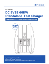
Diagram:
-Steay the CT on the public grid.
-Insert the other end of the communication cable and the terminal of
CT on each side of the adapter.
STEP 11: Push the rear cover to appropriate position of the cables and screw the self tapping screws with the cross screwdriver. Then tighten the
waterproof fastening head.
STEP 12: Hang the EV-Charger up carefully and steady the EV-Charger with the self tapping screw and the cross screwdriver.
(torque: 2~2.5 N·m)
(torque: 2~2.5 N·m)
For type P, connect the charging gun with the EV-Charger
and hang the connecting cable on the hook.
(torque:0.8~1.5 N·m)
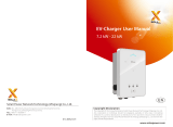
► CT Connection ► WiFi Connection
Step 1: Use your smart phone to scan below QR code or search for
the keyword “SolaXCloud” in browser to download the Monitoring
App.
Step 2: Create a new account on the Monitoring App.
Step 3: Login and turn to Account page in the app. Then click “Wi-Fi
Connection” and follow the instructions to complete the process.
IOS Google
①
③
②
L line
CT
Public grid
electricity
Notice: The arrow on the CT
must point at the public grid.
Electrical
grid
oth er home L oad
PV array
Electricit y meter,
bidirectional
Three -phase Inver te r
L1
N
L2
L3
AC breaker
PE
grid EV- Charger
• Do not place the CT on the N Wire or the PE wire.
• Do not place the CT on the N and L wire
simultaneously.
• Do not place the CT on the non-insulated wires.
• When using the three-phase CT, please clip the CT
clamps on the corresponding phases.
NOTE!