Page is loading ...

Universal Alarm Communicator
Digital Monitoring Products, Inc.
© 2022
PROGRAMMING AND INSTALLATION GUIDE

TABLE OF CONTENTS
About the Communicator ......................1
System Components ...............................1
Terminals.......................................................................1
Programming (PROG) Connection ....................2
Tamper...........................................................................2
Reset Button ...............................................................2
Load Button ................................................................2
Backlit Logo ................................................................3
Mount the Enclosure ................................................3
Wire the Communicator .........................................4
Connect the Antenna ..............................................4
Connect AC Power ...................................................5
Connect Batteries .....................................................5
Connect AC and Battery Trouble Relays to the
DualComNF .................................................................5
Connect AC and Battery Trouble Relays to the
FACP ..............................................................................5
Wiring Specifications...............................................5
AC and Battery Relay Status ................................5
Applications ............................................. 6
CID Dialer Connection .............................................6
Communication Failure ...........................................6
Activate the Cellular Module ................. 7
Dealer Admin Activation ........................................7
Tech APP Activation ................................................7
Remote Link Activation ..........................................7
Programming ...........................................8
Before You Begin ......................................................8
Getting Started ..........................................................8
Programming Menu ..................................................8
Reset Timeout ............................................................9
Special Keys ................................................................9
Letters and Special Characters............................10
Current Programming .............................................10
Initialization .............................................11
Clear All Codes ..........................................................11
Clear All Schedules ...................................................11
Clear Events ................................................................11
Clear Zone Programming .......................................11
Clear Communication ..............................................11
Set to Factory Defaults ...........................................11
Communication .......................................12
Account Number .......................................................12
Transmission Delay ...................................................12
Communication Type ..............................................12
Backup Cell ..................................................................12
Test Time ......................................................................12
Net/Cell Test Days ....................................................12
Check-In Minutes .......................................................12
Fail Time Minutes ......................................................12
Backup Check-In Minutes ......................................12
Backup Fail Time Minutes ......................................12
Receiver1 Programming .........................................12
Receiver2 Programming ........................................13
Network Options .....................................14
DHCP Mode Enabled ...............................................14
Local IP Address ........................................................14
Gateway Address ......................................................14
Subnet Mask ................................................................14
DNS Server ..................................................................14
Programming Port ....................................................14
Remote Options ......................................15
Remote Key .................................................................15
Remote Disarm ..........................................................15
App Key ........................................................................15
System Reports .......................................15
Opening/Closing Reports ......................................15
Zone Restoral Reports ............................................15
Send Stored Messages ............................................15
System Options .......................................16
Entry Delay 1 ...............................................................16
Exit Delay .....................................................................16
Cross Zone Time ........................................................16
Power Fail Delay ........................................................16
Swinger Bypass Trips ..............................................16
Reset Swinger Bypass .............................................16
Time Changes .............................................................16
Hours from GMT .......................................................17
Keypad Input ..............................................................17

ECP Partition Number .............................................17
CID Format ..................................................................17
Output Options .......................................18
Cutoff Outputs ...........................................................18
Output Cutoff Time ..................................................18
Communication Failure Output ...........................18
Armed Output ............................................................18
Remote Arming Output ..........................................18
Area Information .....................................19
Area Number ..............................................................19
Area Name ...................................................................19
Automatic Arming ....................................................19
Automatic Disarming ...............................................19
Zone Information ....................................20
Zone Number ..............................................................20
Zone Name ..................................................................20
Zone Type ....................................................................20
Next Zone .....................................................................21
Alarm Action ...............................................................21
Disarmed Open ..........................................................21
Message To Transmit................................................21
Output Number .........................................................21
Output Action.............................................................22
Swinger Bypass .........................................................22
Cross Zone ...................................................................22
Receiver Routing .......................................................22
Zone Number ..............................................................22
Stop ........................................................... 23
Set Lockout Code ...................................23
Stop ................................................................................23
Set Lockout Code .....................................................23
Appendix ..................................................24
False Alarm Reduction ............................................ 24
Diagnostics Function ...............................................24
Using the 984 Command Function ....................25
NET .................................................................................25
CELL ...............................................................................25
Using the Walk Test ..................................................25
Walk Test ......................................................................25
Trip Counter for Walk Test (STD) ........................25
Test End Warning ......................................................25
Failed Zones Display ................................................25
Cross Zoning ...............................................................26
FCC NOTICE ............................................. 27
Industry Canada ......................................27
NFPA 72 ....................................................27


PowerCom
Programming and Installation Guide Digital Monitoring Products
1
ABOUT THE COMMUNICATOR
The PowerCom™ provides a fully supervised alarm communication path and integrated primary and secondary
communication on one PCB. For commercial fire or residential fire installations, the DualComNF module features
primary network communication, secondary cellular communication, and two sets of tip and ring terminals.
The PowerCom can be used to take over control panels with no need to recalculate standby power requirements. The
communicator can be connected to a control panel’s dialer output and used to capture Contact ID messages based
on SIA DC-05-1999.09-DCS.
The communicator also provides four input zones and two open-collector outputs for connection to control panel
outputs and zones. Connect to the bell output of an existing control panel using zone4 on the communicator. The
communicator operates in a variety of applications: CID Dialer Connection, Zones1-4 Input Connections, or Zone4
Bell Connection. See Applications.
Features
• Powered from 12VDC
• Zone1-4 terminals with 12V
• EASYconnect™
• 2sets of tip and ring terminals
• Programming header for connecting to a programming keypad
• LED to indicate armed state
What is Included
• DualComNF mounted in 505-12 Enclosure
• One Wire-in Transformer
• Battery Leads (One Pair)
• Hardware pack
• External antenna
SYSTEM COMPONENTS
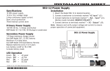
Terminals
Power Connection Terminals
The communicator is powered from the 505-12 12 VDC power supply. The communicator can also be powered by a
backup battery in the event of power failure. See Figure 1.
PowerCom Standby Power
During a power outage, the communicator draws power from a backup battery within the enclosure. Backup batteries
must be provided at the installation site.
Open-Collector Outputs
Terminals O1 and O2 can be programmed to indicate the activity of the zones or conditions occurring on the system.
Open-Collector outputs do not provide a voltage but instead switch-to-ground the voltage from another source.
Maximum voltage is 30VDC at 50mA. The outputs can respond to any of the conditions listed below:
• Activation by zone condition: Steady, Pulse, Momentary, or Follow
• Communication
• Armed area annunciation
• Remote Arming Output
Dialer Connection
Directly connect the Telco phone line (tip and ring) from the control panel to the terminalR(Ring) and one into
terminalT(Tip). For more information, refer to “CID Dialer Connection”.

Digital Monitoring Products
PowerCom
Programming and Installation Guide
2
Programming (PROG) Connection
A 4-pin programming header is provided to connect a keypad to the DualComNF when using a DMP Model330
programming cable. This provides a quick and easy connection for programming the communicator. After
programming is complete, remove the keypad.
Tamper
The tamper is pressed when the cover of the communicator is secured onto the mounting plate base. When the cover
is removed, the communicator sends a tamper trouble message to the central station.
Reset Button
The reset button is located on the upper right side of the circuit board and is used to reset the communicator. After
resetting the communicator, begin programming within 30minutes. If you wait longer than 30minutes, reset the
communicator again.
Note: After the communicator is reset, cell suppression is disabled for 30 minutes.
Load Button
Firmware can be updated with the programming header. Firmware updates are available for download, free of charge,
from DMP’s Product Software Downloads.
Performing a Firmware Update
To update the communicator with a new firmware version, complete the following steps on location:
Remote Link Update
1. Connect a DMP 399 Cable from the programming header to the serial port of your PC operating RemoteLink
and containing the communicator RU file.
2. Start RemoteLink and create or open the account that matches the communicator to be updated.
3. Set the connection information type to direct with a baud rate of 38400 and choose the appropriate COM port.
4. Select Panel > Remote Update, then select the correct RU file for the communicator.
5. Press and hold the load button, then press and release the reset button.
6. Release the load button and select <Update> in Remote Link.
7. After the firmware update is completed, remove the 399 cable and press the reset button to resume normal
operation.
Model401 USB Flash Module
When loading the firmware RU file onto a USB drive, place the file in the root directory of the USB drive. The update
cannot be inside a folder. Format the USB drive as FAT32.
Place only one firmware file in the root directory. If more than one RU file exists on the USB drive, the communicator
will choose the RU file with the most recent date modified.
Caution: Using the wrong RU file for the update will cause the communicator to stop working until the correct RU
file is used to flash the firmware.
1. Connect the USB flash drive to the Model401.
2. Press and hold the reset button on the communicator. You will continue to hold reset until step 6.
3. Connect the assembly to the communicator’s programming header.
4. Press and release the button on the Model401.
5. With your finger still on RESET, press and hold the load button. Continue to hold LOAD until step 8.
6. Release the reset button.
7. Press and release the button on the Model401.
8. When the green LED on the Model401 starts a slow flash, release the load button. The slow flash will last
5minutes, then the green LED will become steady, indicating the firmware version is updated.
Note: If the LED blinks rapidly, the update was unsuccessful. Press and release RESET. Begin again at step1
9. Press and hold RESET. Remove the Model401, then release RESET to resume normal operation.
In the event the Model401 USB Flash Module is inadvertently removed from the communicator before the update
finishes, repeat steps1-9.
Updating Using Dealer Admin
1. Log in to dealer.securecomwireless.com.
2. Select the DualComNF system connected to the account.
3. The System Information page opens. Go to Remote Update.
4. If there are any available updates, select Update System.

PowerCom
Programming and Installation Guide Digital Monitoring Products
3
Backlit Logo
The backlit logo indicates the power and armed status of the communicator. Depending on the operation, the LED
displays in red or green as listed in the Table 1. The LED indicates the armed state and status of the system primary
power.
COLOR AND ACTIVITY OPERATION
Green Steady Communicator Disarmed, Primary Power OK
No Light No Power
Red Steady Communicator Armed, Primary Power OK
Mount the Enclosure
Mount the power supply metal enclosure in a secure, dry location to protect the unit from damage due to tampering
or the elements. It is not necessary to remove the PCB or transformer when installing the enclosure.
Table 1: LED Status
DC
AC
Trouble
Batt
Trouble
Input:
120 VAC 60 Hz 1.5
Amps Unswitched
Green
LED
AC
GRAY
VIOLET
Red
LED
DC
RED
Battery
Wires
(included)
AC and battery
output relay
connections
Factory
Installed
Output:
16 VAC @ 100 VA
Battery
Start
Ground
wire
BLACK
BAT
To Earth
Ground
BLACK
WHITE
GREEN
Model 505-12
This area fits approximately two
batteries.
PROG
LOAD RESET
ETHERNET
S
N
+DC- Z1 Z2 Z3 G +Z4- 01 02 T1 R1 T2 R2
DualComNF
383 Antenna
381-2 Coax Cable
Figure 1: PowerCom Installation

Digital Monitoring Products
PowerCom
Programming and Installation Guide
4
PROG
LOAD RESET
ETHERNET
S
N
+DC- Z1 Z2 Z3 G +Z4- 01 02 T1 R1 T2 R2
Wire the Communicator
When connecting component wires, route all wires so they will not interfere with the tamper switch. See Figure 2 for
wire routing options.
DualComNF SMA
Connector
Figure 2: DualComNF PCB
Network
(Routed behind
Backing Plate)
Tamper
Connect the Antenna
Attach one end of the included coax cable to the DualComNF connector. Refer to Figure 3. Remove the knockout hole
and position one washer onto the other end of the coax cable and push the threaded end through.
Position the second washer onto the threaded end that extends through the antenna knockout hole and secure the
nut. Twist the antenna until it is securely tightened.
Replace the housing cover on the mounted base. Be sure to not damage any PCB components when removing or
replacing the housing cover.
383 Antenna
381-2 Coax Cable
Antenna
Knockout Hole
Coax Cable
SMA Connector
DualComNF
SMA Connector
Brass
Washers
Figure 3: PowerCom Antenna Connection

PowerCom
Programming and Installation Guide Digital Monitoring Products
5
Connect AC Power
Connect the transformer to an unswitched 120 VAC 60 Hz power source with at least 1.5 Amps of available current.
Start by connecting AC power to the black and white transformer leads. Be sure to secure the green wire lead to an
earth ground.
Connect Batteries
Connect the black battery lead to the negative battery terminal and the red battery lead to the positive battery
terminal. Only use sealed lead-acid batteries and replace every 3 to 5 years.
Connect AC and Battery Trouble Relays to the DualComNF
Connect AC TRBL relay outputs from NC (normally closed) and C (common) to one available zone with a 1k resistor
added in sequence and the ground on the DualComNF and program as a Supervisory zone.
Connect BATT TRBL relay outputs from NC (normally closed) and C (common) to one available zone with a 1k resistor
added in sequence and the ground on the DualComNF and program as a Supervisory zone.
Connect AC and Battery Trouble Relays to the FACP
If choosing to connect the FACP to the 505-12, connect the 505-12 AC TRBL supervisory relay output from NC and C
to an available zone on the FACP (with the appropriate resistor in sequence) and program the zone as a supervisory
zone.
Then connect the 505-12 BATT TRBL supervisory relay output from NC and C to an available zone on the FACP (with
the appropriate resistor in sequence) and program the zone as a supervisory zone.
This method may require new battery calculations.
Wiring Specifications
Use 18 AWG or larger for all power connections. Ensure there is a minimum 0.25” space to keep power limited wiring
separate from non-power limited wiring (120 VAC/60 Hz input, battery wires). Properly ground the power supply
before connecting any devices or applying power to the unit.
AC and Battery Relay Status
Relays are form C with the contacts rated at 30 VDC. When an AC trouble or battery trouble occurs, the relay
contacts switch from the NC (normally closed) to the NO (normally open) position. When connected to a panel, an
alarm sounds.
DC
AC
Trouble
Batt
Trouble
Green
LED
AC
Red
LED
DC
RED
AC and battery
output relay
connections
Factory
Installed
Battery
Start
BAT
Model 505-12
PROG
LOAD RESET
ETHERNET
S
N
+DC- Z1 Z2 Z3 G +Z4- 01 02 T1 R1 T2 R2
DualComNF
NC CNC C
Figure 4: 505-12 Power Supply to DualComNF Connection

Digital Monitoring Products
PowerCom
Programming and Installation Guide
6
APPLICATIONS
The communicator can be used in fire detection applications.
CID Dialer Connection
Directly connect one or both tip and ring terminals from the control panel to the communicator. See Figure 5. This
connection captures Contact ID messages from any fire panel that are based on the SIA communication standard
DC-05-1999.09-DCS. Messages are then formatted into a Serial 3 message and sent to an SCS-1R Receiver or SCS-VR
Receiver.
Note: CID Dialer Connection cannot be used when using Zone 4 Bell Connection. Do not connect telephone
company wires to the communicator. Remove any connected telephone company wires from the control panel.
Communication Failure
The phone line voltage on the second tip and ring will drop when the DualComNF is in a communication failure state.
This triggers the host panel to annunciate a communication failure. When communication is restored, voltage is
restored on the second tip and ring terminal and the host panel sees a restoral on the phone line.
Use 18-22 AWG
for Power Supply
connection
+DC- Z1 Z2 Z3 GT1 R1 T2+Z4- R2O1 O2
+
–
Tip 1
Ring 1
12/24 VDC Aux. Output +
-
Ground
Control Panel
The panel or separate power
supply must be listed for fire,
regulated, and power limited.
Telephone
Jack
Connector
BELL -
BELL +
Tip 2
Ring 2
Telephone
Jack
Connector
Wiring to FACP shall be connected within 20 ft in the same room and routed in conduit.
If FACP only has one phone line, connect to T2, R2
Figure 5: Wiring Diagram for Tip and Ring Connection

PowerCom
Programming and Installation Guide Digital Monitoring Products
7
ACTIVATE THE CELLULAR MODULE
For more information about using Dealer Admin, Tech APP, or Remote Link, refer to DMP’s Help Files page.
Dealer Admin Activation
1. Find the customer and select their name.
2. The customer’s summary page opens. In the Systems section, press the Add icon.
3. Enter the system name.
4. In System Type, select DualCom.
5. In Connection Type, select Cellular or EASYconnect + Cell Backup.
6. In SIM Number, enter the SIM number and press Get Status.
7. Press Activate.
8. In Account Number, enter the system’s receiver number followed by the account number.
9. Select a Rate Plan for the communicator.
10. Enter the panel Serial Number.
11. Enter the panel Remote Key. The remote key must match the one programmed in panel REMOTE OPTIONS.
12. To confirm proper communication, press Test Connection.
13. A dialog pops up to ask if you want to perform the initial connection to the panel. Press Yes .
14. Configure additional options as needed, then press Save.
Tech APP Activation
1. Go to the Customer Summary > Systems.
2. Tap the Add icon.
3. Enter the System Name.
4. Enter the panel Serial Number.
5. In System Type, select DualCom.
6. In Connection Type, choose Cellular or EASYconnect + Cell Backup.
7. In Account Number, enter the system’s receiver number followed by the account number.
8. Enter the panel Remote Key. The remote key must match the one programmed in panel REMOTE OPTIONS.
9. Enter the SIM Number and tap Get MEID/SIM Status.
10. Select a Rate Plan for the communicator.
11. Configure additional options as needed, then tap Save.
Remote Link Activation
1. Go to File > Panel Information.
2. Press New.
3. In Model, select DualCom.
4. If necessary, enter a firmware version number in Version.
5. Enter the receiver number and account number, then press OK.
6. In Connection Information, select Cellular.
7. Enter the panel Remote Key.
8. Enter the cellular Phone Number.
9. Press OK.
10. Go to Program > Communications.
11. In Connection, press Activate.
12. Select SIM as the SIM Type.
13. Enter the SIM number, then select a Rate Plan.
14. Press Activate.

Digital Monitoring Products
PowerCom
Programming and Installation Guide
8
PROGRAMMING
Before You Begin
Read this guide before you begin programming. This guide allows you to quickly learn the programming options and
operational capabilities of the DualCom. The communicator contains all of its programming information in an on-
board processor and does not require an external programmer.
In addition to this manual, you should also be familiar with the following document:
• DualCom Communicator Programming Sheet (LT-1860)
Programming Sheet
Fill out the programming sheet included with this device before you begin programming. The programming sheet lists
the various options available for programming the communicator and allows you to keep a record of what options you
intend to enter, reducing programming errors.
Default Master Code
Universal Communicators Version 194 and higher ship with a unique four-digit
default master code. This master code is generated with an algorithm that
ensures it cannot be duplicated. The code can be modified or deleted in panel
programming. To revert the default code to99, use the Clear All Codes option
found in the Initialization menu. Panels ship with the master code on the serial
number label next to the serial number.
Getting Started
Initializing the Communicator
When programming a communicator for the first time or rewriting the entire program of an existing communicator,
use the initialization programming option. See Initialization. Initializing clears the communicator’s memory and sets
the highest user number to user code 99.
Accessing the Programmer
To access the programmer function of the
communicator
:
1. Connect the keypad to the programming header.
2. Press and release the reset button.
3. Enter 6653 (PROG). The keypad displays PROGRAMMER.
Programming Menu
The following is a list of programming menu options available in the programming menu. Press CMD to advance
through the programming menu options. To select a menu option, press any select area when the desired menu
option displays on the keypad. Use this list to navigate to your desired programming menu option in this guide.
• Initialization
• Communication
• Network Options
• Remote Options
• System Reports
• System Options
• Output Options
• Area Information
• Zone Information
• Stop
• Set Lockout Code
MAC : 00:01:22:33:44:55
MOD : DUALCOM
VER : 194 122319
SN : 0012345A CODE21852
TD : 011520
KEY : 100
Default
Master Code

PowerCom
Programming and Installation Guide Digital Monitoring Products
9
Reset Timeout
You must enter the programmer menu within 30minutes of resetting the communicator to avoid reset timeout. After
30minutes, if you attempt to program by entering the 6653 (PROG) code, the keypad displays RESET PANEL. You
must reset the communicator and enter the program code within the next 30minutes.
If you are already in the programmer menu and do not press any keys on the keypad for 30minutes, the
communicator
exits programming. All data entered up to that point is saved in the communicator memory.
To exit the programmer menu, use the stop option. The stop option is the second-to-last option in programming and
disarms all areas. The programming session is terminated and the keypad returns to status list or main screen.
Special Keys
The following keys and areas are common to all DMP LCD and graphic touchscreen keypads.
Command
Press CMD to advance through the programmer menu and through each step of a programming section.
As you advance through the programmer menu, the keypad display any current programming already
stored in the communicator memory. If no change is required for an option, press CMD to advance to the
next step.
CMD is also used to enter information into the communicator’s memory such as an IP address or a zone
name. Press CMD after entering information.
Back Arrow
Use the back arrow to back up one step in a programming menu or to erase a typing error while entering
information.
Select Areas
The top row of keys on LCD Keypads are called select areas. The select areas on graphic touchscreen keypads are
along the top of the keypad. When you need to press a select area, the keypad displays the options.
When there are more than four re sponse options avail able, press CMD to display the next set of options. Press the
back arrow to return to the previous options.
LCD Keypads
The first select area is on the far left. The second select area is second from the left. The third select area is second
from the right. The fourth select area is on the far right and is for special characters. See Figure 6.
Graphic Touchscreen Keypads
When instructed to press the first select area, touch select area 1; the second select area, touch select area2; third
select area, touch select area3; and the fourth select area, touch select area 4. See Figure 7.
CMD
Figure 6: LCD Keypad Select Keys Figure 7: Graphic Touchscreen Keypad Select Areas
First Letter
Second Letter
Third Letter
Special Character
(CBA
32-Character Display
Select Area 1
Select Area 3
Select Area 2
Select Area 4

Digital Monitoring Products
PowerCom
Programming and Installation Guide
10
Letters and Special Characters
Use the number pad directions below to enter letters and special characters on a number pad or use the standard
keyboard directions to enter letters and special characters on a standard keyboard.
Number Pad
1. Choose a character from Table 2.
2. Identify the number the character correlates with and press that number on the number pad.
3. Identify the select area for that character and press that select area on the keypad. To access the lowercase
letter, press that select area again.
4. When the desired character displays on the keypad, return to step1 to enter another character or press CMD if
finished.
NUMBER SELECT KEY 1 SELECT KEY 2 SELECT KEY 3 SELECT KEY 4
1 A B C (
2 D E F )
3 G H I !
4 J K L ?
5 M N O /
6 P Q R &
7 S T U @
8 V W X ,
9 Y Z space _
0 - . * #
Standard Keyboard
• Press ABC to access uppercase letters.
• Press abc to access lowercase letters.
• Press !@# to access symbols and special characters.
• Press 123 to access the number pad.
Note: Not all keypad prompts accept letters and/or symbols. For example, pressing P on the ENTER CODE
prompt could display a 6 on the keypad.
Current Programming
Each programming option that displays shows the information already programmed in the communicator memory. To
change the already programmed information, simply replace the information. To change a programming option that
requires a YES or NO response, press the select area for the desired response.
Table 2: Entering Letters and Special Characters in the Number Pad

PowerCom
Programming and Installation Guide Digital Monitoring Products
11
INITIALIZATION
This option allows you to set the communicator’s programmed memory back to the factory
defaults in preparation for system programming.
After selecting YES to clear a section of memory, the communicator asks if you are sure
you want to clear the memory. This is a safeguard against accidently erasing part of your
programming. No memory is cleared from the programming until you answer YES to the
confirmation prompt.
CLEAR ALL CODES
Choose NO to leave existing codes intact.
Choose YES to clear the user code memory and assign user code number 99 to user20.
CLEAR ALL SCHEDULES
Choose NO to leaves existing schedules intact.
Choose YES to clears all schedules from the programming.
CLEAR EVENTS
Choose NO to leave existing event memory intact.
Choose YES to clear all event memory in the display events buffer.
CLEAR ZONE PROGRAMMING
Choose NO to leave existing zone information intact.
Choose YES to set all zones in the system to *UNUSED*.
CLEAR COMMUNICATION
Choose NO to leave existing communication programming intact.
Choose YES to clear communication to factory defaults.
SET TO FACTORY DEFAULTS
Choose NO to leave the remainder of the existing communicator programming intact.
Choose YES to set the communicator programming back to factory default selections.
Note: Choosing YES does not clear the event memory, zone, user code information, or
schedules.
INITIALIZATION
CODES? NO YES
SURE? YES NO
SCHEDS? NO YES
SURE? YES NO
EVENTS? NO YES
SURE? YES NO
ZONES? NO YES
SURE? YES NO
COMMS? NO YES
SURE? YES NO
DEFAULTS? NO YES
SURE? YES NO
CODES? NO YES
SCHEDS? NO YES
Use YES/NO options to initialize
programmable parts of the panel.
Choose YES to advance to
a confirmation prompt.
If you choose YES, the panel initializes that section
of the program and advances to the next prompt.
If you choose NO, the panel advances to the next
option and does not initialize that section of the
program.
SURE? YES NO
Choose NO to
advance to the
next option.
Figure 8: Alternating Yes and No Options

Digital Monitoring Products
PowerCom
Programming and Installation Guide
12
COMMUNICATION
This option allows you to configure the communication settings for the communicator.
ACCOUNT NUMBER
Enter the account num ber sent to the receiver. The range is 1-65535. For account numbers
of four digits or less, do not enter leading zeros.
TRANSMISSION DELAY
Enter the number of seconds the communicator waits before sending burglary alarm
reports to the receiver. The range is 15-45seconds. The default is 0. Enter 0 to disable this
function.
COMMUNICATION TYPE
The communicator uses NET or CELL to connect with SCS-1R or SCS-VR receivers and
default to NET.
BACKUP CELL
If NET is selected as the primary communication type, BACKUP CELL will display and give
you the option to enable or disable cellular backup.
TEST TIME
Enter the time of day the communicator should send the test report to the SCS-1R or
SCS-VR receivers. Use entries between 12:00 to 11:59 and then choose AM or PM. To enable
daily tests from the host panel, leave the time blank and enable test reports for receiver1
and/or for receiver2. See Test Report.
NET/CELL TEST DAYS
If you entered a test time, you can enter how often the panel test report is sent to the
receiver. The range is 1 to 60 and the default is 1. Enter 0 to disable the test report.
CHECK-IN MINUTES
Check-in reports are a method of supervising the panel for communication with
the receiver. Enter the number of minutes between check-in reports. The range is
3-240minutes. The default is 0. Enter 0 to disable check-in minutes.
Note: Additional cell charges may apply if this option is used.
FAIL TIME MINUTES
Fail time allows the SCS-1R or SCS-VR receivers to miss a defined number of check-ins
before logging that the panel is missing. For example, if cell check-in is 20minutes and fail
time is 30minutes, the receiver only indicates a Panel Not Responding after 30minutes.
The fail time must be equal to or greater than the cell check-in minutes. If cell check-in
is 20minutes, the fail time must be 20minutes or more. The range is 3-240minutes. The
default is 0.
BACKUP CHECK-IN MINUTES
Set the number of minutes between check-in reports for BACKUP CELL if it was enabled.
The range is 3-240minutes. The default is 0. Enter 0 to disable check-in minutes.
Note: Additional cell charges may apply if this option is used.
BACKUP FAIL TIME MINUTES
Set the number of minutes the receiver should wait to indicate that a panel is missing
using BACKUP CELL if it was enabled. If cell check-in is 20minutes, the fail time must be
20minutes or more. The range is 3-240minutes. The default is 0.
RECEIVER1 PROGRAMMING
This option allows you to set the options for the first receiver the communicator attempts
to contact when sending reports from the host panel and/or communicator. The
communicator supports communication up to two receivers.
ALARM REPORTS
Choose YES to enable Abort, Alarm, Alarm Restoral, Alarm Bell Silenced, Ambush, Exit
Error, and System Recently Armed reports to be sent to this receiver. The default is YES.
Choose NO to disable sending these reports to the receiver.
COMMUNICATION
ACCOUNT NO:
XMIT DELAY: 0
COMM TYPE:
NET CELL
BACKUP CELL?:
NO YES
TEST TIME
00:00 AM
NET TST DAYS: 1
CELL TEST DAYS: 1
CHECKIN: 0
FAIL TIME: 0
BACKUP
CHECKIN: 0
BACKUP
FAIL TIME: 0
RECEIVER 1 PROG
ALARM NO YES

PowerCom
Programming and Installation Guide Digital Monitoring Products
13
SUPERVISORY/TROUBLE REPORTS
Choose YES to enable Supervisory, Trouble, Trouble Restoral, Force Armed, and Fault
reports to be sent to this receiver. The default is YES.
Choose NO to disable sending these reports to the receiver.
OPENING/CLOSING AND USER REPORTS
Choose YES to enable Opening/Closing, Schedule and Code Changes, and Bypass reports
by user to be sent to this receiver. The default is YES.
Choose NO to disable sending these reports to the receiver.
TEST REPORT
Choose NO to disable sending these reports to the receiver.
FIRST IP ADDRESS
Enter the first (primary) IP address where the
c
ommunicator sends messages. Enter
all 12digits and leave out the periods. For example, enter IP address 192.168.0.250 as
192168000250. The periods display automatically.
FIRST IP PORT
Enter the first IP port number to be used with the first IP address. The IP port identifies the
port used to communicate messages with the communicator. The default IP port setting is
2001.
SECOND IP ADDRESS
Enter the second IP address where the communicator sends messages. Enter all 12digits
and leave out the periods. The periods display automatically.
SECOND IP PORT
Enter the second IP port number to be used with the second IP address. The IP port
identifies the port used to communicate messages to and from the communicator. The
default IP Port setting is 2001.
RECEIVER2 PROGRAMMING
Set the options for the second receiver that the communicator attempts to contact
when sending reports from the host panel or communicator. The communicator supports
communication with up to two receivers.
Note: If you select YES for any of the receiver2 options, you must have at least one IP
address programmed in receiver2 programming. The receiver2 defaults are set to NO.
ALARM REPORTS
Choose YES to enable Abort, Alarm, Alarm Restoral, Alarm Bell Silenced, Ambush, Exit
Error, and System Recently Armed reports to be sent to this receiver.
Choose NO to disable sending these reports to the receiver. The default is NO.
SUPERVISORY/TROUBLE REPORTS
Choose YES to enable Supervisory, Trouble, Trouble Restoral, Force Armed, Late to Close,
and Fault reports to be sent to this receiver.
Choose NO to disable sending these reports to the receiver. The default is NO.
OPENING/CLOSING AND USER REPORTS
Choose YES to enable Opening/Closing, Schedule and Code Changes, and Bypass reports
by user to be sent to this receiver.
Choose NO to disable sending these reports to the receiver. The default is NO.
TEST REPORT
Choose YES to enable the recall test report from the host panel and/or communicator to
be sent to the receiver.
Choose NO to disable sending this report to the receiver. The default is NO.
FIRST IP ADDRESS
Enter the first (primary) IP address where the
c
ommunicator sends messages. Enter
all 12digits and leave out the periods. For example, enter IP address 192.168.0.250 as
192168000250. The periods display automatically.
SPV/TRBL NO YES
O/C USER NO YES
TEST RPT NO YES
FIRST IP ADDR
000.000.000.000
FIRST IP PORT
2001
SECOND IP ADDR
000.000.000.000
SECOND IP PORT
2001
RECEIVER 2 PROG
ALARM NO YES
SPV/TRBL NO YES
O/C USER NO YES
TEST RPT NO YES
FIRST IP ADDR
000.000.000.000

Digital Monitoring Products
PowerCom
Programming and Installation Guide
14
FIRST IP PORT
Enter the first IP port number to be used with the first IP address. The IP port identifies the
port used to communicate messages with the panel. The default IP port setting is 2001.
SECOND IP ADDRESS
Enter the second IP address where the communicator sends messages. Enter all 12digits
and leave out the periods. The periods display automatically.
SECOND IP PORT
Enter the second IP port number to be used with the second IP address. The IP port
identifies the port used to communicate messages with the panel. The default port is 2001.
NETWORK OPTIONS
DHCP MODE ENABLED
Choose YES if the communicator uses a dynamic IP address. The communicator will
operate in DHCP and will not use the local IP address number. The default is YES.
Choose NO to have the communicator use the IP address entered in local IP address.
LOCAL IP ADDRESS
Enter the local IP address for the communicator. The local IP address must be unique and
cannot be duplicated on the network. The default local IP address is 192.168.0.250.
GATEWAY ADDRESS
Enter the local gateway address. The gateway IP address is needed to exit the local
network. The default gateway address is 192.168.0.1.
SUBNET MASK
Enter the local subnet mask assigned to the communicator. The default subnet mask
address is 255.255.255.000.
DNS SERVER
Enter the IP address of the DNS (Domain Name System) used by the communicator to
resolve domain names into IP addresses. The default address is 0.0.0.0.
PROGRAMMING PORT
Enter the programming port number. The programming port identifies the port used to
communicate messages to and from the communicator. The default programming port
setting is 2001.
FIRST IP PORT
2001
SECOND IP ADDR
000.000.000.000
SECOND IP PORT
2001
NETWORK OPTIONS
DHCP NO YES
LOCAL IP ADDR
192.168.0.250
GATEWAY ADDR
192.168.0.1
SUBNET MASK
255.255.255.0
DNS SERVER
0.0.0.0
PROGRAMMING
PORT 2001

PowerCom
Programming and Installation Guide Digital Monitoring Products
15
REMOTE OPTIONS
This option allows you to enter the information needed for remote command/remote
programming operation.
REMOTE KEY
Enter a code of up to eightdigits for use in verifying the authority of a receiver to perform
a remote command/programming session. The receiver must give the correct key to the
communicator before access will be granted. All communicators are shipped from the
factory with the remote key preset as blank.
To enter a new remote key, press any select area and enter any combination of up to
8digits. The numbers you enter appear as asterisks.
REMOTE DISARM
Choose YES to enable the communicator to be disarmed remotely. The default is YES.
Choose NO to disable remote disarming.
APP KEY
Enter the 8-digit app key obtained in your dealer settings on Dealer Admin. This option is a
security feature of the Virtual Keypad app and is used only when your dealer settings have
EASYconnect set as the communication type. This option is used to eliminate the need
for a static IP address programmed in network options. To enter a new App Key, press any
select area and enter any combination of 8digits. The default is blank.
REMOTE OPTIONS
RMT KEY:
DISARM NO YES
APP KEY:
SYSTEM REPORTS
This option allows you to select which reports the
c
ommunicator sends to the receiver.
OPENING/CLOSING REPORTS
Choose NO to prevent sending opening/closing reports.
Choose YES to send opening/closing reports for each programmed area. The default is
YES.
ZONE RESTORAL REPORTS
Specify whether the communicator sends zone restoral reports and when they will be sent.
Choose NO to prevent sending restoral reports from the communicator.
Choose YES to enable the communicator to send zone restoral reports when a zone
restores from an alarm or trouble condition. The default is YES.
Note: The communicator sends zone restoral reports when a zone that has restored
from an alarm or trouble is disarmed. Twenty-four hour zones send restorals
immediately.
SEND STORED MESSAGES
If a communicator loses communication with the receiver, it will store any messages
that are not able to be sent while communication was down. Selecting YES allows the
communicator to send all stored messages to the receiver once communication is restored.
The time at which each message was generated is also sent. Default is NO.
SYSTEM REPORTS
O/C RPTS NO YES
RESTORAL
NO YES DISARM
SEND STORED
MESSAGES? NO YES

Digital Monitoring Products
PowerCom
Programming and Installation Guide
16
SYSTEM OPTIONS
This option allows you to select system wide parameters used in the operation of the
communicator system.
ENTRY DELAY 1
Enter the entry delay time for all exit type zones programmed. When an armed exit type
zone is faulted, the area must be disarmed before the entry delay expires or a fault will be
detected. All burglary type zones are delayed along with the exit zone. Entry delay times
range from 30-250seconds. The default is 30seconds.
EXIT DELAY
Enter the exit delay time for all exit type zones. When the exit delay time starts, all activity
on exit and burglary zones is ig nored until the exit delay expires. During exit delay, if an exit
zone trips, then restores, and trips again, the exit delay timer restarts. This restart can occur
only once. Exit delay times can be from 30-250seconds. The default is 60seconds.
Exit Error Operation: At arming, when an entry/exit zone (EX) faults at the end of the exit
delay, a zone alarm and an exit error are sent to the receiver.
CROSS ZONE TIME
Enter the time allowed between zone faults. When a zone programmed for cross zoning
faults, the
c
ommunicator begins counting down the cross zone time entered here. If the
same zone or another cross-zoned zone faults within this time, an alarm report is sent to
the receiver.
If the cross zone time expires without the second zone fault, only a zone fault report from
the first zone is sent to the receiver. The cross zone time can be from 4-250seconds in one
second increments. Enter 0 to disable the cross zone time feature. See Cross Zoning.
POWER FAIL DELAY
Enter the time allowed for a power failure to occur before sending a report. The delay time
can be from 1-9 hours. When the power is off for the programmed delay time, a power
failure report is sent to the receiver. For example, if the power failure delay is set for two
hours, then the power failure report will be sent between 2-3 hours. Entering 0 sends the
power failure report within 15seconds.
SWINGER BYPASS TRIPS
Enter the number of times (1-6) a zone can go into an alarm or trouble condition within one
hour be fore being auto matically bypassed. Bypassed zones are auto matically reset when
the area they are assigned to is disarmed. All 24-hour zones are reset when any area of the
system is dis armed. A programming stop operation restores a bypassed zone. Entering 0
disables this function. The default is 2.
How it works
The communicator hour timer starts at 59minutes past the hour. If the hour timer
expires before the trip counter is exceeded, the trip counter returns to 0. If the trip
counter is exceeded before the hour expires, the zone is auto matically bypassed by the
communicator. A bypass re port is sent to the receiver if bypass re ports is set to YES.
RESET SWINGER BYPASS
Choose YES to reset an automatically bypassed zone when it remains in normal condition
for one hour after being bypassed. A report of the automatic reset is sent to the receiver.
Choose NO to disable automatic reset of a bypassed zone. The default is NO.
TIME CHANGES
Choose YES to allow the communicator to request automatic time changes from the
SCS-1R or SCS-VR receiver. The receiver must be programmed to send and receive time
change updates from the host computer at least every 24 hours. Choose NO to disable
automatic time change requests. The default is YES.
SYSTEM OPTIONS
ENTRY DLY 1: 30
EXIT DELAY: 60
CRS ZONE TM:
0
PWR FAIL HRS: 1
SWGRBYPS TRIPS: 2
RST SBYP NO YES
TIME CHG NO YES
/