Page is loading ...

INSTALLATION AND
USE GUIDE
RCE10E

TEMPERATURE CONTROLLER FOR FAN COIL UNIT
RANGE
RCE10E
INSTALLATION AND
USE GUIDE
INDEX
1.0.0 USER GUIDE 2
1.1.0 GENERAL RECOMMENDATION 2
1.2.0 Description of the unit 3
1.2.1 Setpoint knob (A) 3
1.2.2 Adjustment scale (B) 3
1.2.3 Setting switch (C) 3
1.2.4 Setting switch (D) 3
1.2.5 Setting switch (E) 3
1.2.6 Led mode (F) 3
1.2.7 Led filter (G) 3
1.2.8 Hidden button (SW1) 3
1.3.0 Using the unit 3
1.3.1 Cooling 3
1.3.2 Heating 3
1.3.3 Night fuction 3
1.4.0 Warning of dirty filter 3
1.4.1 Alarm indication 3
1.4.2 Information given by the leds 3
1.0.0 INSTALLER GUIDE 4
2.1.0 General description 4
2.2.0 Technical data 4
2.3.0 Installation 4
2.3.1 Installation position 4
2.3.2 Connections 5
2.4.0 Description of inputs and outputs 5
2.4.1 Analog inputs (External measurement sensors) 5
2.4.2 Installing and enabling the sensors 5
2.4.3 Digital inputs (clean contacts necessary) 6
2.4.4 Outputs 6
2.4.5 Anti-freeze function 6
2.5.0 Methods of control 6
2.5.1 Fan 6
2.5.2 Destratification cycle 6
2.6.0 Applications 6
2.6.1 2-pipe fan coil control 6
2.6.2 2-pipe fan coil control (heating with electric. heater only) 6
2.6.3 4-pipe fan coil heating and cooling control 7
2.6.4 2 or 4-pipe fan coil control 7
2.6.5 Starting sequence 7
2.7.0 Table of parameters 7
2.7.1 General description 7
2.7.2 Table of parameters 7
2.7.3 Setting and changing the parameters 7
2.7.4 Checking the set parameters 7
2.7.5 Configurable parameters 8
2.8.0 Electric wiring diagram 9
1.0.0 USER GUIDE
1.1.0 GENERAL RECOMMENDATION
1. Keep this booklet in a readily accessible place for future reference.
2. Before touching the instrument, make sure that the electricity has
been cut off.
3. Caution: the parts inside the instrument are live.
4. No parts inside the instrument are useable by the user.
5. This product must be installed by qualified personnel only, in
compliance with current safety regulations.
6. The product has been designed according to current safety standards.
Failure to comply with safety regulations and standards during
installation as well as failure to comply with the instructions in this
booklet could, however, reduce the safety level. The environmental
conditions given under technical data must be observed in particular.
Avoid contact with liquids, the formation of condensation, use of
corrosive liquids and exposure to impact or excessive stress.
7. The product guarantees a level of immunity against interference in
conformity with CE directives. Devices to be connected to the product
and the electrical system in general must have characteristics that
are compatible with the levels of immunity guaranteed for the product.
8. The product is not galvanically isolated from the mains voltage supply.
All loads, accessories or sensors connected to it should therefore
be considered as subjected to hazardous potential. The use of
sensors with double insulation is recommended as well as the use
of centralised controls or switches, which ensure double isolation
for all parts accessible to the user.
9. The product may be connected to other similar products. Scrupulously
comply with the envisaged connection instructions, observing all the
polarities. Failure to comply with these instructions could cause short
circuits, which are damaging for the product and hazardous for the
user.
10. The outputs towards the loads are unprotected against short circuits
or overtemperature. It is therefore recommended that all suitable
measures are taken to avert these possibilities, such as correct
dimensioning of the loads, protective fuses, overtemperature
protectors, etc.
11. The power supply inputs are unprotected against incorrect paralleling
of several products. The use of protective fuses, magnetothermal
circuit breakers, etc. is therefore recommended to prevent short
circuits caused by incorrect installation.
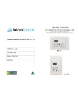
Fig. 1
2
SW1
OFF
A
ON
C
O
M
F
O
R
T
-
+
CDE
B
G
F
F
I
L
T
E
R
M
O
D
E
A

RCE10E
INSTALLATION AND
USE GUIDE
1.3.3 Night Function (Economy).
Put the selector switch C to the Moon position.
The Comfort temperature is reduced by 4°C in the heating mode and
increased by 3°C in the cooling mode. This function allows energy
consumption to be reduced at night or when there is no-one in the room.
1.4.0 WARNING OF DIRTY FILTER
During normal fan coil operation a filter retains the impurities present in
the air. This filter must be cleaned periodically otherwise fan coil efficiency
suffers. The FILTER LED warns that the filter must be cleaned by blinking
slowly once every 5 seconds. Refer to the instructions given in the Fan
Coil operating and maintenance manual. When the LED blinks:
- cut off the electricity supply to the fan coil;
- clean the filter.
After cleaning, reconnect the fan coil to the power supply and keep the
key SW1 pressed for 5 seconds; the LED blinks quickly for 5 seconds
and then goes out. The appliance starts operating as normal.
1.4.1 Alarm indication
If the appliance is malfunctioning, the Filter LED comes on with a fixed
red light.
If this happens, contact the firm that installed the appliance.
1.4.2 Information given by the LEDs
1.2.0 DESCRIPTION OF UNIT CONTROLS
The following controls are be found on the unit (Fig. 1):
1.2.1 Setpoint knob (A).
This is used to change the desired temperature value (Setpoint) by +/-
5°C in relation to the preset Comfort value. The Comfort value is 20°C
when the appliance is in the heating mode and 25°C in the cooling mode.
The temperature may therefore be regulated between 15 and 25°C when
heating and between 20 and 30°C when cooling.
1.2.2 Adjustment scale (A).
This consists of points arranged in a circle and a central area shown as
Comfort. Turn the knob to the left to decrease the temperature (each
point = 1°C less) and to the right to increase the temperature (each point
= 1°C more).
1.2.3 Setting switch (C)
OFF: appliance switched off. The antifreeze function remains active.
ON: appliance in operation with temperature adjusted according to
the settings
MOON: appliance operates in the Economy mode (night function).
1.2.4 Setting switch (D)
A: Automatic. The appliance automatically varies the fan speed of
rotation to optimise the Comfort state.
1: First speed. The fan (when on) always operates at minimum speed.
2: Second speed. The fan (when on) always operates at medium
speed.
3: Third speed. The fan (when on) always operates at maximum speed.
1.2.5 Setting switch (E)
UMBRELLA (summer): appliance operates in the cooling mode.
SNOWMAN (winter): appliance operates in the heating mode;
HEATING ELEMENT: appliance operates in the heating mode using
the additional heating element;
NOTE: if the appliance has been programmed during installation for
automatic or centralised switching between Heating and Cooling, the
selector switch E may only be used for switching on the additional heating
element. The Umbrella and Snowman positions are ignored.
1.2.6 MODE LED (F): this indicates the mode of operation of the
appliance (see below for details).
1.2.7 FILTER LED (G): this indicates that the fan coil filter is dirty. It is
also used to indicate an alarm in progress (see below).
1.2.8 HIDDEN BUTTON (SW1) (to be used during installation) for editing
parameter programming.
1.3.0 USING THE UNIT
1.3.1 Cooling: put the selector switch E to the Umbrella symbol (summer)
Put the selector switch D to A (automatic).
Put the knob A to Comfort (25°C).
Put the selector switch C to ON.
The Mode LED first blinks with a green light, which then remains fixed.
The fan coil starts to cool the room. The fan speed of rotation is adjusted
automatically for maximum efficiency.
Upon reaching the Comfort temperature the Mode LED blinks with a
yellow light once every 5 sec. Use knob A to change the temperature
as desired. Use the selector switch D to change the motor speed of
rotation manually.
1.3.2 Heating: put the selector switch E to the Snowman symbol (winter)
Put the selector switch D to A (automatic).
Put the knob A to Comfort (20°C).
Put the selector switch C to ON.
The Mode LED first blinks with a red light, which then remains fixed.
The fan coil starts to heat the room. The fan speed of rotation is adjusted
automatically for maximum efficiency.
Upon reaching the Comfort temperature the Mode LED blinks with a
yellow light once every 5 sec. Use knob A to change the temperature
as desired. Use the selector switch D to change the motor speed of
rotation manually. If the additional heating element is installed, put the
selector switch E to the Heating Element position to switch it on.
Red continuous: alarm
Red blinking
1sec ON, 1 sec OFF: dirty filter
LED MODE
Colour System status
Red continuous: Active heat valve and fan
Red blinking with fan on: heat valve OFF, the fan is about to
stop
Red blinking with fan off: heat valve ON, the fan is about to
start
Green continuous: active cool valve and fan
Green blinking with fan on: cool valve OFF, the fan is about to
stop
Green blinking with fan off: cool valve ON, the fan is about to
start
Orange blinking setpoint reached, Comfort mode
1sec ON, 5sec OFF:
Orange blinking setpoint reached, Economy mode
1sec ON, 1sec OFF:
LED FILTER
3

TEMPERATURE CONTROLLER FOR FAN COIL UNIT
RANGE
RCE10E
INSTALLATION AND
USE GUIDE
2.1.0 GENERAL DESCRIPTION
The unit consists of 2 parts: the installation base and the control
unit (see Fig. 2):
The installation base is wall mounted or fixed to a 503 module using two
screws. The base has screw terminals for the electrical connections.
The control unit is fixed onto the base by an automatic coupling system
(fig. 6).
The base terminals have the following functions (fig. 2):
M1 Auxiliary output (auxiliary heating element)
M2 Cooling valve output
M3 Heating valve output (or primary heating element)
M4 Phase for power outputs
M5 Fan speed 3 output
M6 Fan speed 2 output
M7 Fan speed 1 output
M8 Power supply input (Phase 230 Vac)
M9 Power supply input (Neutral 230 Vac)
M13 Remote air sensor input (AIR)
M14 Water sensor input (AQ)
M15 Analog and digital input common (Neutral)
M16 Centralised S/W switching input
M17 Economy input
M18 Window contact input
2.0 INSTALLER GUIDE
Fig. 2
2.2.0 TECHNICAL DATA
Power supply: 230Vac +/-10%, 50 60Hz
Absorption: 0.8 VA +/- 15%
Outputs
Fan: TRIAC 250Vac, 3(2.5)A max
Valves: TRIAC 0.6A
Auxiliary output: TRIAC 0.6A max
Temperature adjustment range:+15...+30°C selectable with software
parameters and knob (A) +/- 5°K
Proportional band: selectable between: 2,3,4,5 °K
Neutral area (dead zone): selectable between: 3,4,5°K
Temperature sensors: NTC type sensors 10K +/- 0.3°K @ 25°C with
double insulated cable, section 0.5 mm2 min, 1.5mm2 max, maximum
length 20 m.
Adjustment precision during normal operation: +/- 0.5°C in relation to
25°C room temperature setpoint
Maximum variation in precision with room temperature: +/-0.3°C from
10 °C to 30°C
Antifreeze temperature: 4°C
Factory configuration: see Default parameters table
Storage temperature: -20 ... +55°C
Working temperature: +0 . +50°C, 0 . 95 % r.h.
Housing protection rating: IP30
Connections: screw terminals for wires with section of 1.5 sq. mm.
CE conformity: LVD 73/23: standard EN 60730-1
EMC:EN 55014-1 (or EN 50081-1)
EN55014-2 (or EN 50082-1)
Size: 122 x 68 x 29 mm (WxHxD) - fig. 4
Weight: 120 grams
2.3.0 INSTALLATION
2.3.1 Installation position
The controller must be located 1.5 m from the floor in a position where
there is good circulation of air.
It must not be affected by:
- currents or dead areas behind doors or in corners;
- hot or cold air from ducts;
- sunlight, household electrical appliances or unheated (non-cooled)
areas, such as outside walls behind the thermostat, embedded pipes or
flues (fig. 3).
Fig. 4
Fig. 3
Control unit interior
Terminal block with all connections
LN
I
II
III
M
4
5
21
4
3
188
7
69
1514
13
17
16
OFF
A
ON
C
O
M
F
O
R
T
-
+
122
6829
1,50 m
123456789 131415161718
Auxiliary heating element
Cooling valve
Heating valve
Power supply 230Vac
±10% - 50-60 Hz
Motor
Air sensor
Water sensor
Neutral common
Summer/winter SW
ECONOMY
Window

RCE10E
INSTALLATION AND
USE GUIDE
2.3.2 Connections
Lay the necessary cables for connection between the control unit and
the fan coil, including those for any sensors and auxiliary inputs, as
specified below.
Fix the installation base to the wall or on top of a 503 box using 2 screws.
Carry out the connections to the terminal block.
Carefully check the connections.
Place the control unit on top of the base, gently pushing it until the 2
parts lock together.
Connecting cables between room unit and fan coil and between
room unit and centralised controls.
The connecting cables must have the following characteristics:
between room unit and fan coil;
section: 1.5mm2
insulation: 250 Vac
maximum length: 20 m
between room unit and centralised controls;
section : 1.5 mm2
insulation: 250 Vac
maximum length: 20 m
It is advisable to lay the cables to the actuators and the power supply
in conduits other than those for the sensor and centralised control cables.
Fig. 6
Fig. 5
2.4.0 DESCRIPTION OF INPUTS AND OUTPUTS
2.4.1 Analog inputs (External measurement sensors)
Temperature sensors with the characteristics described under Technical
Data may be connected to the analog inputs M13 and M14.
Sensors with other characteristics may not be connected.
The air and water sensors are optional. The air sensor is used for
measuring the room temperature for example on the air intake of the
fan coil.
The water sensor is used to carry out the change of season in the
automatic mode according to the temperature of water entering the fan
coil or as minimum temperature acknowledgement for starting the fan
coil both in the heating and the cooling modes.
2.4.2 Installing and enabling the sensors
Air sensor (M13-M15)
The appliance is fitted with an internal sensor for measuring the room
temperature. If an external sensor is necessary, proceed as described
below. The sensor is installed on the air intake of the fan coil.
If connected, the instrument acknowledges this sensor as active, ignoring
the internal sensor.
If it is not connected, the instrument acknowledges the internal sensor
as active.
Water sensor (M14-M15)
This measures the water outlet temperature for the automatic
Cooling/Heating switching (only on 2-pipe systems).
Install the sensor upstream of the regulating valve, as shown in figure
7. Note: the valve must be 3 way.
If the regulating valve is not installed, the water sensor may be used
for the automatic Summer/Winter switching and Acknowledgement
for Fan Start (both in the summer and winter modes).
Put the sensor between the exchanger fins as shown in figure 8.
A thermostat (TC) may be used instead of the water sensor for the
sole function of fan acknowledgement:
open contact= summer fan acknowledgement;
closed contact= winter fan acknowledgement.
In a double coiled fan coil (4-pipe system), the water sensor may only
be used as acknowledgement for fan start in the heating mode. Put the
sensor between the heat exchanger fins. To change the assigned function
of the water sensor, the parameters 2, 9, 10 must be set as indicated
in table 1.
Parameter 2 to define the type of system.
Parameter 9 to define whether or not the switching must depend on the
water sensor.
Parameter 10 to define the function of the water sensor.
Some examples for 2-pipe systems (See table 1).
Fig. 8
Water sensor
Fan acknowledgement
Fan coil
Fig. 7
Water sensor
Summer/Winter
Fan coil with
regulating valve
3-way regulating
valve
5
TO DISCONNECT
83
TO CONNECT

TEMPERATURE CONTROLLER FOR FAN COIL UNIT
RANGE
RCE10E
INSTALLATION AND
USE GUIDE
No sensor, set:
Parameter 2= 2 pipes + 1 sol.v
Parameter 9= manual
Parameter 10= absent
For automatic Summer/Winter switching, set:
Parameter 2= 2 pipes + 1 sol.v.
Parameter 9= H2O/Cont
Parameter 10= S/W switching
For acknowledgment of fan activation only, set:
Parameter 2= 2 pipes + 1 sol.v.
Parameter 9= manual
Parameter 10= fan ack.
2.4.3 Digital inputs (clean contacts necessary)
Digital inputs 16-17-18 may be paralleled with other products
provided all the polarities are strictly observed.
Economy Function (M15 and M17).
open contact = comfort status.
The temperature is adjusted according to the position of knob A.
closed contact = economy status (Heating = value set with the knob
-4°C/ cooling = set value +3°C). A timer may be connected to
the input to make this function automatic.
Window contact (M15 and M18).
closed contact: the valve(s) close(s), the fan stops and the heating
element switches off thereby saving energy, The anti-freeze function
remains active.
open contact: normal operation (comfort)
A timer may be connected to inputs M15 and M18 to make this function
automatic.
The function of the contact may be reversed (see parameter 5)
Summer/Winter switching (M15 and M16).
This input is used for the centralised Summer/Winter switching rather
than manual selection using the switch E.
To activate the function it is necessary to set:
Parameter 9= H2O/Cont and
Parameter 10= Absent
If these parameters are not configured in this way, the input is
ignored.
open contact: heating mode (WINTER)
closed contact: cooling mode (SUMMER).
2.4.4 Outputs
Fan (M4 - M5 - M6 - M7):
For fan with three speeds, 230 Vac, 50-60 Hz
Maximum current: 3 A
Heat valve (M3 - M4):
for actuator control at 230 Vac, 50-60Hz
with regulation: ON-OFF, PWM, HEAT (parameter 4)
Cool valve (M2 - M4):
for actuator control at 230 Vac, 50-60Hz with regulation: ON-OFF,
PWM, HEAT (parameter 4). The maximum current absorbed by the
actuators must be 0.8 A.
Auxiliary output (M1 - M4): an electric heating element may be
connected to this output (through a power relay) to boost the heating
function obtainable with the heat exchanger of the fan coil.
It may control a load at 230Vac, 50-60 Hz.
The absorbed current must be between 10 mA and 0.8A inclusive.
The following may be connected as an alternative to the heating element:
A humidifier
A motor for external air intake damper
A motor for the fan coil airflow outlet louvers
To enable the function, see parameter 6.
2.4.5 Anti-freeze function
The anti-freeze function is always active. When the room temperature
falls below 4°C, the heat valve opens thereby preventing any damage
to the water circuit. This function does not enable the fan.
IThe thermostat controls ventilation in an intelligent way in order to:
prevent frequent changes in speed
avoid unwanted ventilation
prevent condensation or overheating of the systems
2.5.2 Destratification cycle
When ventilation is thermostat-controlled, upon reaching setpoint a
destratification cycle is activated to improve the precision of adjustment.
The fan operates for 2 minutes at minimum speed every 15 minutes.
2.6.0 APPLICATIONS
2.6.1 2-pipe fan coil control
(cooling + heating with water coil and regulating valve+ possible additional
heating element) - Fig. 10. Set Parameter 2= 2 pipes + 1 SOL.V.
The control commands an electrothermal actuator and the fan coil fan.
The actuator must be connected to terminals 3-4.
The fan is controlled as indicated in paragraph 2.6.1
If a heating element is connected to the auxiliary output terminals (M1
M4), the heating element activates in the heating mode to boost
heating when the selector switch E is in the heating element position
and Tamb<Setpoint
2.6.2 2-pipe fan coil control
(cooling with water coil and regulating valve, heating with electrical
heating element only) - Fig. 11.
Set Parameter 2= 2 pipes with heating by elect. heat. el. only.
For cooling, the control commands an electrothermal actuator.
For heating, the control commands a heating element.
The actuator must be connected to terminals 2-4.
The electrical heating element must be connected to terminals 3-4.
The fan is controlled as indicated in paragraph 2.6.1.
If a second heating element is connected to the auxiliary output terminals
(M1 M4), the heating element boosts the main element in the heating
mode when the selector switch E is in the heating element position and
Tamb<Setpoint.
2.6.3 4-pipe fan coil heating and cooling control
(+ 2 heat/cool regulating valves) - Fig. 12.
Set Parameter 2 =4 pipes + SOL. V
The cooling/heating switching may be automatic, manual or centralised.
Automatic switching with neutral area.
2.5.0 METHODS OF CONTROL
2.5.1 Fan
Fan operation is regulated to ensure a correct flow of heated (or chilled)
air during the various operating phases.
Fan operation may be:
Thermostat-controlled: when set point is reached, the fan switches
off.
Continuous: the fan is always active, even when setpoint is reached.
The fan speed may be:
Constant: the selector switch D is put to position 1 or 2 or 3.
Automatic: the selector switch D is put to position A.
In this case the speed changes automatically in relation to the room
temperature, as indicated in fig. 9.
Fig. 9
FAN 1
FAN 2
FAN 3
NEUTRAL
BAND
TEMPERATURE
SET POINT
HEAT
SET POINT
COOL
SET POINT
FAN
SPEED
HEAT PROPORTIONAL BAND COOL PROPORTIONAL BAND
0
1
2
3
6

RCE10E
INSTALLATION AND
USE GUIDE
Upon completion of the sequence, the controller returns to normal
operation. If a selector switch is activated during the sequence, the
sequence stops and normal operation is resumed.
2.7.0 TABLE OF PARAMETERS
2.7.1 General description
The controller has a series of configurable parameters, which make
it suitable for various applications.
The parameters may be configured directly on the thermostat following
the procedure described in 2.8.3.
2.7.2 Table of parameters.
An arbitrary parameter called RESET also appears in the table, which
may be used to reset all the factory parameters with one action (factory
settings column)
2.7.3 Setting and changing the parameters.
The control has a button (SW1) in the lower right part, for accessing
the parameter programming mode and to enter the selection (ENTER).
The central knob of Setpoint (A) is used to select the type of parameter
(from 1 to 10) see table of parameters.
The selector switch D is used to set the value of the selected parameter
(see table of parameters).
The LED on the right (MODE) visually indicates with green or red the
value at which the parameter selected with D has been set.
The LED on the left (FILTER) blinks fast in the parameter programming
mode.
To enter the parameter programming mode, proceed as follows:
Turn A fully counter-clockwise (position 5 degrees).
Put C to OFF.
Put D (fan speed selector) to AUTO.
Put E (season change selector) to SUMMER.
Press the button SW1 for at least 5 seconds. The FILTER LED blinks
for the whole time that the user remains in the parameter programming
mode.
3 seconds after entering the parameter mode, the MODE LED comes
on with a green light if the actual parameter corresponds to the value
selected by D. The LED comes on with a red light if the actual
parameter is not the same as the set one (see table1).
To enter a new value, place D on the selected value, (the MODE
LED comes on with a red light) press the button SW1 and wait for the
MODE LED to come on with a green light.
Proceed in the same way for all the parameters to be changed.
To save the new settings in the permanent storage of the system,
press SW1 for at least 5 seconds. The MODE LED blinks 3 times with
a green light to confirm that the new parameters have been saved.
Upon completion of storage, the controller exits from the parameter
setting mode automatically.
2.7.4 Checking the set parameters
Shift A to select the required parameters
Upon moving D, if the MODE LED turns green = the corresponding
value in the table of parameters is currently active
Upon moving D, if the MODE LED turns red = the corresponding
value in the table of parameters is not currently active.
To exit from the parameter checking mode, wait for 2 minutes without
touching the button SW1.
The control automatically controls the heat valve to start heating and
the cool valve to start cooling.
Set Parameter 9= T ambient (room temp).
The width of the neutral zone may be changed with parameter 1.
The Cooling/Heating switching is automatic according to the room
temperature and the neutral zone.
The fan is controlled as indicated in paragraph 2.6.1.
Manual switching.
In this case the Cooling/Heating switching is manual (using selector
switch E)
Set Parameter 9 = Manual
The fan is controlled as indicated in paragraph 2.6.1
Centralised switching.
In this case the Cooling/Heating switching is accomplished using the
input M16
Set Parameter 9 = H2O/contact.
Set Parameter 10 = Absent.
The fan is controlled as indicated in paragraph 2.6.1
If a heating element is connected to the auxiliary output terminals (M1
M4), the heating element activates in the heating mode to boost
heating when the selector switch E is in the heating element position
and Tamb<Setpoint.
2.6.4 2 or 4 pipe fan coil control
(without regulating valve + possible electrical heating element) Fig.
13.
Set Parameter 2= Fan only
The control is already set for control of just the fan
The cooling/heating switching may be automatic, manual or centralised.
Manual switching.
Set Parameter 9 = Manual.
The Cooling/Heating switching is manual using selector switch E
Centralised switching.
Set Parameter 9 = H2O/cont.
Set Parameter 10 = Absent.
In this case the Cooling/Heating switching is accomplished using the
input M16
Automatic Summer/Winter switching (for
2 pipe systems only)
Set
Parameter 9=H2O/Contact M16
Parameter 10 = S/W switching
In this case the Cooling/Heating switching depends on the temperature
of the outflowing water.
If a heating element is connected to the auxiliary output terminals (M1
M4), the heating element activates in the heating mode to boost
heating when the selector switch E is in the heating element position
and Tamb<Setpoint.
2.6.5 Starting sequence
To carry out a first test of all the functions upon completion of installation,
proceed as follows:
Put the Setpoint knob to +5 °C (fully to the right)
Put C to OFF, D to 3, E to Heating Element
Press SW1 for approx. 5 seconds until the MODE LED blinks red
and green alternately and the FILTER LED blinks fast
Fan speed 1 activates for 10 seconds
Fan speed 2 activates for 10 seconds
Fan speed 3 activates for 10 seconds
Fan speed 1 activates again
The heat valve actuator activates for a time T and then stops
The cool valve actuator activates for a time T and then stops
The auxiliary output activates for 5 seconds.
The sequence ends automatically at the end of the cycle. It can also
be stopped by pressing the button SW1 at any time.
N.B. The actuator control time T is:
5 seconds when parameter 4= ON/OFF and PWM
180 seconds parameter 4= Thermal
7

TEMPERATURE CONTROLLER FOR FAN COIL UNIT
RANGE
RCE10E
INSTALLATION AND
USE GUIDE
2.7.5 Configurable parameters
Table 1
N.o
POSITION "D"
1 Wint. / Sum. setpoint W/S Setpoint value setting -5 20/25 (d.z.= 5) 20/24 (d.z. =4) 21/23 (d.z.= 2) - 20/25 (d.z.= 5)
2 Type of system Defines the type of system -4
2 pipes + 1 SOL. V. 4 pipes + 2 SOL. V. 2 pipes with heat only Heat. El. Fan only (2/4 pipes) w/out SOL.V. 2 pipes+1 SOL.V.
3 Fan Defines if the fan is thermostat-controlled or continuous -3 Thermostat-controlled Wint. therm/Sum. cont. Continuous in W/S Sum. therm./Wint. cont. Thermostat-controlled
4 Type of outputs Defines the actuator control mode -2 Thermal On/OFF PWM - Thermal
5 Window contact Defines if the window contact is active when closed or open C Closed=Active Open=Active - - Closed=Active
6 Aux. output function Defines the auxiliary output function F Heating el. Humid./Dehumid. Damper Grille Heat. el.
7 Temperature offset Corrects the temperature value read by the air sensor T 0 -2 +1 +2 0
8 Set variation limit Limits the Setpoint variation for the user turning the knob +2 ±5 °C ±2°C ±3°C ±4°C ±5 °C
9 S/W switching Switching between Cooling and Heating +3 Manual H2O sensor/contact M16 From room temp. - Manual
10 Water sensor Fixes the function of the water sensor (AQ) +4 Fan acknowledgement Absent S/W switching - Fan acknowledgement
Reset Resets all parameters to factory values (default) +5 - Reset - - -
PARAMETER TO BE SET DESCRIPTION OF PARAMETERS
POSITION A
SELET.
A
POSITION SPEED 1 POSITION SPEED 3
POSITION SPEED 2
FACTORY
SET POINT
OFF
A
ON
C
O
M
F
O
R
T
-
+
F
I
L
T
E
R
M
O
D
E
CE
8

RCE10E
INSTALLATION AND
USE GUIDE
Fig. 10
Fan coil with 2 pipes + 1 cool only valve
(cooling with water coil and regulating
valve, heating with electrical heating element only)
Fig. 11
Fig. 12
Fig. 13
Fan coil with 2 pipes + 1 valve (cooling +
heating with water coil and regulating valve)
+ possible additional heating element
Fan coil with 4 pipes for cooling and
heating (+ 2 heat/cool regulating valves)
Fan coil with 2 or 4 pipes (without regulating valve)
possible heating element
TC
III II I
M
LN
TC
III II I
M
LN
13 14 15 16 17 18
TC
III II I
M
LN
TC
III II I
M
LN
2.8.0 ELECTRIC WIRING DIAGRAM
9
13 14 15 16 17 18
13 14 15 16 17 18
123456789
Air sensor
Water sensor
Neutral common
S/W switching cont
ECONOMY Cont.
Window cont.
Auxiliary heating
element
Heat/cool valve
Principal heating
element
Power supply 230 Vac
Motor
123456789
123456789
123456789 131415161718
Air sensor
Water sensor
Neutral common
S/W switching cont
ECONOMY Cont.
Window cont.
Power supply 230 Vac
Motor
Auxiliary heating
element
Air sensor
Water sensor
Neutral common
S/W switching cont
ECONOMY Cont.
Window cont.
Auxiliary heating
element
Heat/cool valve
Power supply 230 Vac
Motor
Auxiliary heating
element
Heat valve
Cool valve
Air sensor
Water sensor
Neutral common
S/W switching cont
ECONOMY Cont.
Window cont.
Power supply 230 Vac
Motor

TEMPERATURE CONTROLLER FOR FAN COIL UNIT
RANGE
RCE10E
INSTALLATION AND
USE GUIDE
10

RCE10E
INSTALLATION AND
USE GUIDE
11

All data in this technical manual are no binding for Eden S.r.l. company who takes the right, without
advance notice obbligation, to provide to any modification for product improvements.
MI RCE10E 0000 1104 EDEN GB
EDEN s.r.l.
Via dell'Artigianato, 11 - 31010 Fonte (TV) - ITALY
Tel. (0039) 0423 567 774 r.a. - Fax (0039) 0423 567 985
/