Page is loading ...

Electric Strike
AL110
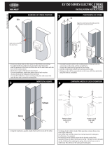
PACK CONTENTS
MOUNTING STEPS OF STRIKE
INSTALL ON METAL OR ALUMINUM DOOR FRAME
DOOR LATCH POSITION
1 For aluminum or metal door frame brackets are
supplied for assembly, refer to Figure 2. For timber
door frame refer to Figure 3. mark and drill the hole
sizes as indicated on Figure 2 and Figure 3.
2 Make sure electrical connections are followed
correctly.
3 When the door is closed, ensure that there is no
pressure on the front face of strike keeper.
4 When all the above checks are completed, secure
the strike with supplied screws and recheck
operation.
As shown in Figure 1, there must be a 1mm gap between the door latch
and the front face of strike keeper to prevent the door from exerting
pressure on the keeper when door is closed.
Read all instructions before starting installation
POWER INPUT 12 VDC or 24 VDC SUPPLY:
x 4
x 2
x 2
Remove
rubber plug
prior to
assembly of
extension lips
(2 places)
Depth of lip
cutout will
vary due to
width of door
frame and
mounting
technique
15mm, 25mm,
50mm, 75mm,
extension lips
are available
options
Fig.1
Fig.2
Note: There is no polarity on power input. AL110
model is not equipped with monitoring sensor.
RED RED
YELLOW BLUE
BLUE YELLOW
BLACK BLACK
DSS (Door Status Sensor) BLACK (COM) BLUE (NO)
ORANGE (NC)
DSS contact rating: max, current 100 mA, max.
voltage 30 vDC
1
2
3
4
12 vDC/
200 mA
24 vDC/
100 mA

AL1982-35.5
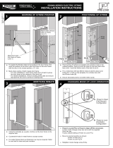
Procedures to convert Fail Secure (Figure 4A) to Fail Safe (Figure 4B):
Step 1: Remove the spring screw from the end part of the strike body.
Step 2: Remove the Barbell to reverse in position with long side in and
short side out.
Step 3: Replace the spring screw.
Procedures to convert Fail Safe (Figure 4B) to Fail Secure (Figure 4A):
Step 1: Remove the spring screw from the end part of the strike body.
Step 2: Remove the Barbell to reverse in position with short side in and
long side out.
Step 3: Replace the spring screw.
WARNING: Do not attempt to swivel the keeper while changing the function, this will damage the barbell
mechanism.
www.alpro.co.uk
01202 676262
01202 680101
Harwell Road Nuffield Estate Poole Dorset BH17 0BD Great Britain
Registered in England & Wales 1925537 © June 2018 IEC. All rights reserved. All dimensions are nominal and subject to tolerances
AL110
Electric Strike
Remove
rubber plug
prior to
assembly of
extension lips
(2 places)
Lipless
11.6
Depth of lip
cutout will
vary due to
width of door
frame and
mounting
technique
15mm, 25mm,
50mm, 75mm,
extension lips
are available
options
INSTALL ON TIMBER DOOR FRAME
POWER TO LOCK (FAIL SAFE) <=> POWER TO OPEN (FAIL SECURE) CONVERSION
ELECTRIC STRIKE MAINTENANCE
Fig.3
1
2
Fig. 4A
POWER TO OPEN (FAIL TO SECURE)
Fig. 4B
POWER TO LOCK (FAIL SAFE)
Spring
Screw
Barbell
Spring
Screw
Barbell
Ensure on a regular; basis the whole of the door system is
checked (lock case, door closer, strike plate, handles etc.)
to ensure the desired level of door operation and security
is being maintained
PLEASE NOTE:
The warranty for the strike is void if:
The strike is assembled incorrectly
Parts fitted to the strike which are not approved Alpro Parts
The strike is incorrectly wired
There is incorrect voltage applied to the strike
Alpro electric strikes should be installed by suitably
qualified engineers
Maintenance should be carried out every 6 months, or
higher for heavy duty door traffic.
Electric strikes should be fitted exactly in accordance with
the Alpro fixing instructions, ensuring and maintaining all
relevant door gaps and clearances.
Under no circumstances use a spray lubricant, as this type
of solvent can damage electronics. Electrical parts with
the strike need no maintenance.
If required fit a protective diode as close to the coil as
possible to protect the system from transient peaks
/