Page is loading ...

Monitored Electric Strike
AL2000
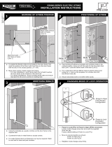
Read all instructions before starting installation
As shown in Figure 1, there
should be 1mm gap between
the door latch and the front
face of strike keeper to prevent
the door from exerting back
pressure on the keeper when
the door is closed.
When door is closed, make sure there is no back
pressure on the keeper strike.
When the above installation is completed,
connect the wiring, secure the strike with
appropriate screws and check operation.
Note: The control circuit for the door strike is protected against reverse polarity
connection.
PACK CONTENTS
DOOR LATCH POSITION
INSTALL ON METAL FRAME
MOUNTING STEPS OF STRIKE
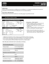
Power Input 12 vDC - current 220 mA 24 vDC - current 110 mA
Wire output Red (+) Black (-)
LSS (Lock Status
Sensor)
Black (Common)
Yellow (NO-PTO),
NC-PTL)
Green (NC-PTO),
(NO-PTL)
DSS (Door Status
Sensor)
Black (Common) Blue (NO) Orange (NC)
ATS (Anti-Tamper
Sensor)
Black (Common) Red (no) White (NC)
Sensor Output
LSS Sensor Output 3A,
125 vAC, 2A, 30 vDC
DSS Sensor Output
3A, 125 vAC, 2A,
30 vDC
Anti-tamper Sensor
Output 5A, 125 vAC,
3A, 250 vAC
POWER INPUT 12VDC OR 24VDC SUPPLY
1
2
x4
x2 x1
x2
x1
x1
x2

Monitored Electric Strike
AL2000
Read all instructions before starting installation
POWER TO LOCK (PTL) <=> POWER TO OPEN (PTO) CONVERSION
Step 1: Remove the rubber cap to expose the capstan
wheel. See Figure 3.
Step 2: Slacken the capstan release screws two full
revolutions. DO NOT REMOVE. See Figure 3.
Step 3: Insert the “tool pin” through the cover end opening
hole and operate the solenoid hold it in position
and at the same time insert the “tool” thru the cover
plate opening hole and turn the capstan gear in the
direction of the keeper to the stop. See Figure 4.
Step 4: The strike is now in the Power to Lock mode.
Step 5: Tighten the two capstan releasing screws and
replace the rubber cap. See figure 5.
Procedures to convert PTO (Power to open) to PTL (Power to lock)
Registered in England & Wales 1925537 © A
pril 2018 IEC. All rights reserved. All dimensions are nominal and subject to tolerances
ELECTRIC STRIKE MAINTENANCE
Maintenance should be carried out every 6 months, or higher for
heavy duty door traffi
c.
Electric strikes should be fitted exactly in accordance with the
Alpr
o fixing instructions, ensuring and maintaining all relevant door
gaps and clearances.
Under no circumstances use a spray lubricant, as this type of
solvent can damage electronics. Electrical parts with the strike
need no maintenance.
If required fit a protective diode as close to the coil as possible to
protect the system from transient peaks.
Ensure on a regular; basis the whole of the door system is checked
(lock case, door closer, strike plate, handles etc.) to ensure the
desired level of door operation and security is being maintained.
PLEASE NOTE:
The warranty for the strike is void if:
The strike is assembled incorrectly
Parts fitted to the strike which are not approved Alpro Parts
The strike is incorrectly wired
There is incorrect voltage applied to the strike
Alpro electric strikes should be installed by suitably qualified
engineers
Figure 3 Figure 4
Step 1: Remove the rubber cap to expose the capstan
wheel. See Figure 3.
Step 2: Slacken the capstan release screws two full
revolutions. DO NOT REMOVE. See Figure 3.
Step 3: Insert the “tool pin” through the cover end opening
hole and operate the solenoid hold it in position and
at the same time insert the “tool” through the cover
plate opening hole and turn the capstan gear in the
direction of the keeper to the stop. See Figure 6.
Step 4: The strike is now in the Power to Open mode.
Step 5: Tighten the two capstan releasing screws and
replace the rubber cap. See figure 5.
Procedures to convert PTL (Power to lock) to PTO (Power to open)
Figure 5 Figure 6
/