Page is loading ...

Part No. ES150 - 121 - 0816
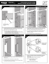
• Ensure any rebate strips or door stops are fitted before proceeding.
To enable the Electric strike to be located in the door frame, first
mark the position of the Door Latch front face on the door frame with the
door in the closed position.
• Mark where centre of latch meets door frame:
- For new installations, mark frame where front of latch touches
the door frame at the midpoint of the latch bolt.
- For retrofit installations, remove existing strike plate and ensure that
latch fits into and is centred in existing hole.
• Centrally locate the strike in the marked position, lining up both the
centre hole on the strike and the marked frame.
Position the strike hard up against the door frame.
• Hold the strike firmly in place and mark around the edge .
• Making sure the drill is perpendicular to the frame, drill three pilot holes
using the strike as a template.
Mark Centre of latch on
the door frame
Align the centre hole on the strike over the
marked line on the door frame.
33
4mm
• Using the markout as a guide, neatly chisel out the recess for the strike .
92mm
Small End of
Spring
Short Pins
Long Pin
Short Pins
Long Pin
Power to Open
(Fail-Secure)
Fig 1
Power to Lock
(Fail-Safe)
Fig 2
To change electric strike’s mode of lock operation, remove brass screw
from top of strike body.
Invert strike and carefully release the small spring and 3 locking pins
(2 x Short pin, 1 x Long pin).
Re-insert pins in the manner shown for the desired mode of lock
operation (Power to Open / fail Secure): see Fig. 1; (Power to Lock / fail safe):
see Fig. 2, followed by replacing the spring. Screw in the brass screw to
strike body. This will secure the spring and locking pins.
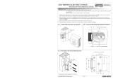
ES150 SERIES ELECTRIC STRIKE
INSTALLATION INSTRUCTIONS
MARKING OF STRIKE POSITION
POSITIONING OF STRIKE
MORTICING REBATE CHANGING MODE OF LOCK OPERATION
P/n

ASSA ABLOY Australia Pty Limited, 235 Huntingdale Rd, Oakleigh, VIC 3166 ABN 90 086 451 907 ©2016
Recommended 4mm Gap
Minimum 1mm Working Gap
• Once door frame preparation is complete, temporarily fit strike into
door frame to check for interference. Check that the door closes
smoothly and that the latch extends fully past the strike keeper.
• When strike operates correctly with latch, remove strike from
mortice and connect wiring.
• Refit strike and secure, making sure no wires are being crushed.
• Check both mechanical and electronic operation works correctly.
ELECTRICAL SPECIFICATION
CAUTION! - Incorrect supply voltage may cause damage not covered by warranty.
Please check supply voltage with a suitable meter to ensure it is within ± 15% of the nominal
voltage shown above with the strike powered.
DO NOT OIL OR LUBRICATE
24V DC 125mA 12V DC 250mA
Blue Red
Black
White
Blue
Red
White
Black
•
• •
•
•
•
•
•
Blue and Black to Power Supply.
Red and White joined together.
Red and Black joined and to Power Supply.
Blue and White joined and to Power Supply.
•
•
/