Page is loading ...

AL110 ANSI
ELECTRIC STRIKE
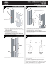
DOOR LATCH POSITION
1mm
Keeper
Door latch
Front face of
strike keeper
Keeper
Door Frame
Door
Figure 1
As shown above, there must be a 1mm gap between the door latch and the front face of strike keeper to
prevent the door from exerting pressure on the keeper when door is closed.
MOUNTING STEPS OF STRIKE
1). For aluminum or metal door frame brackets are supplied for assembly, refer to Figure 2.
For timber door frame refer to Fig. 3. mark and drill the hole sizes as indicated on Figure 2 and Figure 3.
2).
Make sure electrical connections are followed correctly.
3).
When the door is closed, ensure that there is no pressure on the front face of strike keeper.
4).
When all the above checks are completed, secure the strike with supplied screws and recheck operation.
POWER INPUT 12 VDC or 24 VDC SUPPLY:
Note: There is no polarity on power input. AL110 model is not equipped with monitoring sensor.
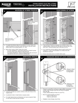
INSTALL ON METAL OR ALUMINUM DOOR FRAME
38
156 (A) or 232.3 (B)
124.7 (A) or 201(B)
86
6.5
Mounting on metal door
32.7(A) or 36(B)
17(A) or 18.8(B)
Mounting on aluminum or PVC door
Latch area
Front face of
strike keeper
10 x
6 csk screw hole 2 places.
Note: 1. (A) refer to small faceplate with actual size 123.7 x 31.7 x 3mm
Figure 2
2. (B) refer to large faceplate with actual size 200.0 x 35.0 x 3mm
3.
All sizes in millimeter.
2
0
.5
25mm, 50mm, 75mm extension
lips are available options
Depth of lip cutout will vary
due to width of door frame
and mounting technique
Remove rubber plug
prior to assembly of
extension lips (2 places).

INSTALL ON TIMBER DOOR FRAME
86
2
0
.
5
36
20.5
3
Figure 3
25mm, 50mm, 75mm extension
lips are available options
Depth of lip cutout will vary
due to width of door frame
and mounting technique
Remove rubber plug
prior to assembly of
extension lips (2 places).
38
86
6.5
latch area
105.2 (A) or 181.5 (B)
Note: 1. (A) refer to small faceplate with actual size 123.7 x 31.7 x 3mm
2. (B) refer to large faceplate with actual size 200.0 x 35.0 x 3mm
3. All sizes in millimeter.
Front face of strike keeper
Wire hole
124.7 (A) or 201.0 (B)
32.7(A) or 36(B)
17(A) or 18.8(B)
POWER TO LOCK (FAIL SAFE) <=> POWER TO OPEN (FAIL SECURE) CONVERSION
POWER TO LOCK
Spring screw
POWER TO OPEN
Barbell
Spring screw
Figure 4A
Figure 4B
Barbell
( FAIL SAFE )
( FAIL SECURE )
WARNING: Do not attempt to swivel the keeper while changing the function, this will damage the
barbell mechanism.
Procedures to convert Fail Secure (Figure 4A) to Fail Safe (Figure 4B):
Step 1: Remove the spring screw from the end part of the strike body.
Step 2: Remove the Barbell to reverse in position with long side in and short side out.
Step 3: Replace the spring screw.
Procedures to convert Fail Safe (Figure 4B) to Fail Secure (Figure 4A):
Step 1: Remove the spring screw from the end part of the strike body.
Step 2: Remove the Barbell to reverse in position with short side in and long side out.
Step 3: Replace the spring screw.
/