Page is loading ...

ES9000 SERIES ELECTRIC STRIKE
INSTALLATION INSTRUCTIONS
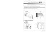
CHANGING MODE OF LOCK OPERATION
Power to Lock (PTL) to Power to Open (PTO) conversion.
Loosen mode change screw two turns with the supplied
2mm hex key.
Factory default setting is Power to Lock (PTL)
Move to required position as shown:
Power to Open Fig. A
Power to Lock Fig. B
Retighten mode change screw firmly.
2
POSITIONING OF STRIKE
Peel backing off adhesive template and centrally locate in the
marked position, lining up both the mark for the door latch front
face (Line 1) and the centre mark of the latch (Line 2).
For a metal door drill two Ø5mm holes (A) 22mm above and
below the ‘x’ mark on the template, for a timber door drill
two Ø3mm holes (B).
Ensure secondary bolt is not within strike cavity.
Hole 'B'
Metal Door Frame Timber Door Frame
Strike
cavity
22mm
22mm
Hole 'A'
Line 1
Line 2
A - Power to Open
(Fail-Secure)
Configuration
B - Power to Lock
(Fail-Safe)
Configuration
4
R
S
T
ICK-
TP0
0
0
Depth of lIp cutout will vary due
outline
S
c
r
ibe
Crack and peel back to stIck
template to face of door frame
O
N
TEMP
L
A
TE
Front face of lock latch
ES200-ES2000
ES9000
to width of door frame and
mounting technIque.
S
T
ICK-
TP0
0
0
Depth of lIp cutout will vary due
outline
S
c
r
ibe
Crack and peel back to stIck
template to face of door frame
O
N
TEMP
L
A
TE
Front face of lock latch
ES200-ES2000
ES9000
to width of door frame and
mounting technIque.
Part No. ES9000-121
30621 1008
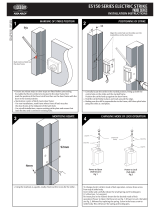
Using the template as a guide, mortice out the door frame to the
required size.
Countersink holes in metal frame to accept screws.
For wider framed doors an Extension Lip may be required. Refer
to over leaf for sizes and part numbers.
MORTICING REBATE
3
24mm
To enable the Electric strike to be located in the door frame, first
mark the position of the Door Latch front face on the door frame
with the door in the closed position, ('X ' mm).
Mark where centre of latch meets door frame:
- For new installations, mark frame where front of latch touches
the door frame at the midpoint of the latch bolt.
- For retrofit installations, remove existing strike plate and ensure
that latch fits into and is centred in existing hole.
Frame
Frame
Door
Door
Latch
Mark Door latch
front face on frame
(Line 1).
MARKING OF STRIKE POSITION
1
'X ' mm
'X ' mm
Mark centre of Door
latch on frame
(Line 2).
Line 1
Line 2

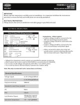
Fig. 4 - Monitoring SchematicFig. 4 - Monitoring Schematic
Solenoid Wiring
Solenoid Return (0V)
Red
Black
Solenoid Power
(10-30V DC)
100-300mA
Common
N.O. (Normally Open)
Yellow
Violet
Brown
N.C. (Normally Closed)
Latch Monitor Wiring
Door Opened
Solenoid Monitor Wiring:
Unpowered
Common
N.C. (Normally Closed)
Grey
Orange
White
N.O. (Normally Open)
ELECTRICAL SPECIFICATION
Door mounting bracket
Refit strike and secure, making sure no wires are being crushed.
Check both mechanical and electronic operation works correctly.
CHECKING FUNCTION
6
TUBULAR LATCH OPERATION
To ensure deadlatching, ensure
that the deadlatching pin is
depressed by the edge of the
keeper when the door is closed.
Deadlatching
pin.
Keeper
edge.
CAUTION! Incorrect supply voltage may cause damage not covered by warranty.
Please check supply voltage with a suitable meter to ensure it is within 10-30V DC.
Current required is 250mA @12V DC to 130mA @ 24V DC
DO NOT OIL OR LUBRICATE.
9000 Series Microswitch Monitoring
The 9000 Series Electric Strike has back EMF protection built into the product.
No external protection diode is required.
The wiring diagram for the monitoring schematic is shown in Fig. 4 and on the
back of the strike.
ASSA ABLOY Australia Pty Limited, 235 Huntingdale Rd, Oakleigh, VIC 3166 ABN 90 086 451 907 ©2008
An ASSA ABLOY Group brand
5 Year Limited Warranty
ASSA ABLOY Australia guarantees for a period of 5 years in accordance with Trimec’s
Standard Warranty Conditions, against defects in manufacture, workmanship or materials,
provided that all electrical and mechanical installation requirements are adhered to as per
this datasheet. All third party and consequential claims are expressly excluded from
the warranty.
2 5mm Extension lip
50mm Extension lip
75mm Extension lip
P/No. 220200-505
The installation of a Strike guard is recommended on outward opening
external doors.
P/No. 220200-506
P/No. 220200-507
warranty
4 Hr
FIRE RATED
ASSEMBLING STRIKE
5
For metal door frames fit door mounting brackets.
Once door frame preparation is complete, temporarily fit strike into
door frame to check for interference. Check that the door closes
smoothly and that the latch extends fully past the strike keeper.
When strike operates correctly with latch, remove strike from
mortice and connect wiring.
Ensure wires come out
of back as shown
/