Page is loading ...

USER MANUAL
Firmware Versions 1.xxx - 4.002
PowerFlex® 700S High Performance AC Drive -
Phase II Control

PowerFlex 700S Phase II AC Drive User Manual
Important User Information
Solid state equipment has operational characteristics differing from those of
electromechanical equipment. Safety Guidelines for the Application,
Installation and Maintenance of Solid State Controls (Publication SGI-1.1
available from your local Rockwell Automation sales office or online at
http://
www.rockwellautomation.com/literature) describes some important differences
between solid state equipment and hard-wired electromechanical devices.
Because of this difference, and also because of the wide variety of uses for solid
state equipment, all persons responsible for applying this equipment must
satisfy themselves that each intended application of this equipment is
acceptable.
In no event will Rockwell Automation, Inc. be responsible or liable for indirect
or consequential damages resulting from the use or application of this
equipment.
The examples and diagrams in this manual are included solely for illustrative
purposes. Because of the many variables and requirements associated with any
particular installation, Rockwell Automation, Inc. cannot assume responsibility
or liability for actual use based on the examples and diagrams.
No patent liability is assumed by Rockwell Automation, Inc. with respect to use
of information, circuits, equipment, or software described in this manual.
Reproduction of the contents of this manual, in whole or in part, without
written permission of Rockwell Automation, Inc. is prohibited.
Throughout this manual, when necessary we use notes to make you aware of
safety considerations.
Important: Identifies information that is critical for successful application and
understanding of the product.
PowerFlex, DriveExplorer, DriveTools SP, DPI, and SCANport are either trademarks or registered trademarks of Rockwell Automation, Inc.
Klixon
®
is a registered trademark of Sensata Technologies, Inc.
!
WARNING: Identifies information about practices or
circumstances that can cause an explosion in a hazardous
environment, which may lead to personal injury or death, property
damage, or economic loss.
!
ATTENTION: Identifies information about practices or
circumstances that can lead to personal injury or death, property
damage, or economic loss. Attentions help you identify a hazard,
avoid a hazard, and recognize the consequences.
Shock Hazard labels may be located on or inside the equipment
(e.g., drive or motor) to alert people that dangerous voltage may be
present.
Burn Hazard labels may be located on or inside the equipment
(e.g., drive or motor) to alert people that surfaces may be at
dangerous temperatures.

PowerFlex 700S Phase II AC Drive User Manual - Publication 20D-UM006G-EN-P – July 2008
Summary of Changes
Manual Updates
This information summarizes the changes to the PowerFlex 700S High
Performance AC Drive - Phase II Control User Manual, publication
20D-UM006, since the January 2007 release.
Change See Page...
Updated the Catalog Number Explanation Preface-5
Added information for “Single-Phase Input Power” operation 1-9
Updated the “Disconnecting MOVs and Common Mode Capacitors” section for frames 5 and 6
drives
1-17
The following parameters were updated for firmware version 4.002: 3-1-3-115
Updated the Parameter Cross Reference By Name table 3-118
Added new “Ride Thru” (F92) fault 4-11
Updated the drive rating current value for single-phase operation A-3
Separated the drive ratings information from the drive protection devices - now in separate tables
and added frame 14 drive data
A-7, A-17
Added a note regarding overwriting parameters when performing a download to drive from a HIM
set using the Copycat function
D-4
Added the Allen-Bradley 842HR rotary encoder to the list of supported encoders F-2, H-2
Added new 2090-XXNFMF-SXX cable wiring diagram for use with HPK-Series Motors and rotary
encoders
F-3, H-2
Added a note regarding the use of certain permanent magnet motors in constant velocity
applications
I-1
7[Motor Poles] 400 [Rated Amps] 825 [Dig In1 Sel]
153 [Control Options
] 408 [Power Loss Level] 826 [Dig In2 Sel]
156 [Start Inhibits
] 415 [BusReg/Brake Ref] 827 [Dig In3 Sel]
266 [Heidn Encdr Type
] 466 [MC TP1 Select] 828 [Dig In4 Sel]
267 [Heidn Encdr PPR
] 471 [Estimated Torque] 830 [Dig In6 Sel]
329 [Fault TP Sel
] 473 [MC TP2 Select] 1125 [DC Brake Level]
370 [HiHp InPhsLs Cfg
] 513 [V/Hz Mode Config]

soc-2
PowerFlex 700S Phase II AC Drive User Manual - Publication 20D-UM006G-EN-P – July 2008
This information summarizes the changes to the PowerFlex 700S High
Performance AC Drive - Phase II Control User Manual, publication
20D-UM006, since the August 2006 release.
This information summarizes the changes to the PowerFlex 700S High
Performance AC Drive - Phase II Control User Manual, publication
20D-UM006, since the March 2006 release.
Change See Page...
Updated the “Important” information regarding the use of an Auxiliary Power Supply with Voltage
Feedback boards on drives manufactured before June 2006.
1-23
The following new parameters were added for firmware versions 4.001: 3-1-3-115
The following parameters were updated for firmware version 4.001: 3-1-3-115
Added the “Electronic Gear Ratio” Group to the User Function file. 3-14
Added required encoder PPR rating values A-4
Updated the “Inputs & Outputs - Digital” block diagram to reflect new values B-11
Added the new “Virtual Master Encoder” block diagram B-19
Updated the “User Functions 2” block diagram B-21
Updated parameter names in the “Inverter Overload IT” block diagram B-25
Added an “Application Note” regarding Motor Overload Memory Retention C-6
Change See Page...
Updated the Catalog Number Explanation Preface-5
Added a note for Frame 6 power terminals connections 1-12
Added a note to indicate that the Analog Inputs are not isolated 1-24
Added maximum value calculation for Par 81 [Spd Reg P Gain] 3-19
Added note referencing “Cable Tuning Tests” to Par 268 [Resolver0 Cnfg] 3-42
Added bit 14 to Pars 322 [Exception Event3], 325 [Fault Status 3], and 328 [Alarm Status 3] 3-48, 3-49,
3-49
Added a note for value 1 “FOC 2” for Par 485 [Motor Ctrl Mode] 3-70
Updated Par 796 [Posit Gear Ratio] to be linkable 3-94
459 [IdsCompCoeff Mot] 592 [VqsReg On Hystr] 1166 [EGR Pos Preset]
460 [IdsCompCoeff Reg
] 593 [SlipReg On Hystr] 1170 [MC Generic 1]
461 [SlipReg Off Iqs
] 1124 [Home Actual Pos] 1171 [MC Generic 2]
462 [VqsReg Off Freq
] 1155 [Heidn VM Pos Ref] 1172 [MC Generic 3]
544 [External DB Res
] 1156 [Heidn VM Enc PPR] 1173 [MC Generic 4]
586 [IdsCmd Slew Rate
] 1160 [VirtEncPositFast] 1174 [MC Generic 5]
587 [SlipReg Err Lmt
] 1161 [EGR Config] 1175 [MC Generic 6]
588 [VqsReg Err Lmt
] 1162 [EGR Mul] 1176 [MC Generic 7]
589 [Err Count Lmt
] 1163 [EGR Div] 1177 [MC Generic 8]
590 [RsTempCoefAdjust
] 1164 [EGR Pos Input] 1178 [MC Generic 9]
591 [RsTmpCoefAdjstEn
] 1165 [EGR Pos Output] 1179 [MC Generic 10]
153 [Control Options
] 512 [PMag Mode Config] 826 [Dig In2 Sel]
156 [Start Inhibits
] 515 [FVC Tune Config] 827 [Dig In3 Sel]
161 [Logic TP Sel
] 533 [SlewRateTimeLimt] 828 [Dig In4 Sel]
263 [Heidenhain0 Cnfg
] 553 [Slip Slew Rate] 829 [Dig In5 Sel]
264 [Heidenhain0 Stat
] 701 [FdbkAxis FdbkSel] 830 [Dig In6 Sel]
266 [Heidn Encdr Type
] 788 [Xsync In 1] 1000 [UserFunct Enable]
267 [Heidn Encdr PPR
] 789 [Xsync Out 1] 1122 [Home Speed]
277 [Reslvr0 Type Sel
] 790 [Xsync In 2] 1123 [Home Position]
314 [VPL Firmware Rev
] 791 [Xsync Out 2] 1136 [PPMP Rev Spd Lim]
357 [Curr Ref TP Sel
] 792 [Xsync Out 2 Dly] 1137 [PPMP Fwd Spd Lim]
360 [Min Flux
] 793 [Xsync In 3] 1138 [PPMP Over Ride]
457 [MC Firmware Rev
] 794 [Xsync Out 3] 1145 [PPMP TP Select]
466 [MC TP1 Select
] 795 [Xsync Out 3 Dly]
510 [FVC Mode Config
] 825 [Dig In1 Sel]

soc-3
PowerFlex 700S Phase II AC Drive User Manual - Publication 20D-UM006G-EN-P – July 2008
This information summarizes the changes to the PowerFlex 700S High
Performance AC Drive - Phase II Control User Manual, publication
20D-UM006, since the September 2005 release.
Updated the description for options 34 “UserGen Sel0” - 37 “UserGen Sel3” for Pars 825 - 830 3-97
Added a list of parameters corresponding to the value selected in Par 831 [Anlg Out1 Sel] 3-98
Updated the description for Par 1022 [Sel Switch Ctrl] 3-107
Added new fault code 79 “HiHP Bus Data” 4-11
Updated the Bus Overvoltage Trip levels A-1
Added information on DPI device limitations A-6
Update the “Drive, Fuse & Circuit Breaker Ratings” tables A-17
Updated the DriveLogix - Motion Control Block Diagram B-28
Updated wiring diagram for Rotary Encoder connections F-4, H-4
Added new Appendix for SynchLink Specifications K-1
Change See Page...
Updated the Power Terminal Block Specification Descriptions 1-12
Updated the Terminal Block specifications for digital input leakage current 1-24
Updated the HIM Start Up Menu diagram 2-7
Updated the Min./Max. values for parameter 75 [Rev Speed Limit] 3-18
Updated the Min./Max. values for parameter 76 [Fwd Speed Limit] 3-18
Added values 9 and 10 to parameter 150 [Logic State Mach] 3-24
Added value 8 to parameter 165 [Tune Test Status] 3-29
Updated the trigger Source settings for parameter 236 [RegisLtch 0/1Cnfg] 3-35
Changed parameter 321 [Exception Event2] / bit 14 to a non-configurable alarm 3-48
Changed parameter 322 [Exception Event3] / bit 11, 12, 13, 21 and 28 to a non-configurable
alarms
3-48
Changed parameter 324 [Fault Status 2] / bit 14 to a non-configurable alarm 3-48
Changed parameter 325 [Fault Status 3] / bit 21 to Drive Homing” and bit 28 to “+/- 12v Pwr” 3-49
Changed parameter 327 [Alarm Status 2] / bit 14 to a non-configurable alarm 3-49
Changed parameter 328 [Alarm Status 3] / bit 21 to Drive Homing” and bit 28 to “+/- 12v Pwr” 3-49
Added values 45, 46 and 47 to parameter 347 [Drive OL TP Sel] 3-53
Added values 20 - 52 to parameter 357 [Curr Ref TP Sel] 3-54
Changed bit 3 to “FastFluxDsbl” for parameter 510 [FVC Mode Config] 3-72
Changed bit 3 to “FastFluxDsbl” for parameter 513 [V/Hz Mode Config] 3-73
Updated the default and Min./Max. values for parameter 532 [Maximum Frequency] 3-76
Change bit 18 to ”Vqs Reg Act” for parameter 555 [MC Status] 3-78
Added bit 9 “Watch Fb Arm” and bit 10 ”WatchFbPosit” to parameter 691 [Motn EventStatus] 3-84
Added bit 7 “Watch Fb Rev” to parameter 692 [Motn Event Ctrl] 3-84
Updated Parameter 554 [LED Status] to include a description 3-77
Updated the description for bit 7 “AbsoluteMode” of parameter 740 [Position Control] 3-90
Updated the description for bit 0 “Absolute” of parameter 1134 [PPMP Control] 3-114
Updated fault 33 “+/- 15volt Power” to new voltage band settings 4-8
Added new event 86 “Drive Homing” 4-11
Added new event 93 “+/- 12volt Power Alarm” 4-11
Updated the Specifications table for C-tick Agency Certification, drive sound levels, and encoder
voltage supply data.
A-1
Updated the Drive, Fuse & Circuit Breaker Ratings tables. A-17
Updated wiring diagram for Rotary Encoder connections. H-4
Added new Appendix for ATEX approved PowerFlex 700S Phase II Drives in Group II Category (2)
applications with ATEX approved motors.
J-1
Change See Page...

soc-4
PowerFlex 700S Phase II AC Drive User Manual - Publication 20D-UM006G-EN-P – July 2008
This information summarizes the changes to the PowerFlex 700S High
Performance AC Drive - Phase II Control User Manual, publication
20D-UM006, since the August 2005 release.
Change See Page...
The following new parameters were added for firmware versions 3.01: 3-1-3-115
49 [Selected SpdRefA] 732 [PLL Posit OutAdv] 1114 [DelTmr2 Trig Bit]
50 [Selected SpdRefB
] 733 [PLL FiltPositOut] 1115 [DelayTimer2PrSet]
54 [Inertia TrqLpfBW
] 734 [PLL Speed Out] 1116 [DelayTimer2Accum]
119 [SLAT ErrorSetpnt
] 735 [PLL SpeedOut Adv] 1117 [DelayTimer2Stats]
120 [SLAT Dwell Time
] 848 [Dig Out1 On Time] 1120 [Home Accel Time]
341 [Mtr I2T Count
] 849 [Dig Out1 OffTime] 1121 [Home Decel Time]
368 [Cnv NotLogin Cfg
] 853 [Dig Out2 On Time] 1122 [Home Speed]
533 [SlewRateTimeLimt
] 854 [Dig Out2 OffTime] 1123 [Home Position]
551 [CurrFdbk AdjTime
] 858 [Rly Out3 On Time] 1125 [DC Brake Level]
552 [Slip Preload Val
] 859 [Rly Out3 OffTime] 1126 [DC Brake Time]
553 [Slip Slew Rate
] 1093 [Anlg In1LossCnfg] 1130 [PPMP Pos Command]
554 [LED Status
] 1094 [Anlg In2LossCnfg] 1131 [PPMP Pos Mul]
669 [Write Mask
] 1095 [Anlg In3LossCnfg] 1132 [PPMP Pos Div]
712 [Write Mask Act
] 1096 [AddSub 1 Input] 1133 [PPMP Scaled Cmd]
713 [Logic Mask Act
] 1097 [AddSub 1 Add] 1134 [PPMP Control]
714 [Port Mask Act
] 1098 [AddSub 1 Subtrct] 1135 [PPMP Status]
717 [PLL TP Select
] 1099 [AddSub 1 Result] 1136 [PPMP Rev Spd Lim]
718 [PLL TP DataDInt
] 1100 [AddSub 2 Input] 1137 [PPMP Fwd Spd Lim]
719 [PLL TP DataReal
] 1101 [AddSub 2 Add] 1138 [PPMP Over Ride]
720 [PLL Control
] 1102 [AddSub 2 Subtrct] 1139 [PPMP Accel Time]
721 [PLL Position Ref
] 1103 [AddSub 2 Result] 1140 [PPMP Decel Time]
722 [PLL BandWidth
] 1104 [AddSub 3 Input] 1141 [PPMP SCurve Time]
723 [PLL Rev Input
] 1105 [AddSub 3 Add] 1142 [PPMP Spd Output]
724 [PLL Rev Output
] 1106 [AddSub 3 Subtrct] 1143 [PPMP Pos Output]
725 [PLL EPR Input
] 1107 [AddSub 3 Result] 1144 [PPMP Pos To Go]
726 [PLL EPR Output
] 1108 [DelTmr1 TrigData] 1145 [PPMP TP Select]
727 [PLL VirtEncdrRPM
] 1109 [DelTmr1 Trig Bit] 1146 [PPMP TP DataDInt]
728 [PLL Ext Spd Ref
] 1110 [DelayTimer1PrSet] 1147 [PPMP TP DataReal]
729 [PLL Ext SpdScale
] 1111 [DelayTimer1Accum] 1150 [DInt2Real2 In]
730 [PLL LPFilter BW
] 1112 [DelayTimer1Stats] 1151 [DInt2Real2 Scale]
731 [PLL Posit Out
] 1113 [DelTmr2 TrigData] 1152 [DInt2Real2Result]

soc-5
PowerFlex 700S Phase II AC Drive User Manual - Publication 20D-UM006G-EN-P – July 2008
Change See Page...
The following parameters were updated for firmware version 3.01: 3-1-3-115
The following new fault codes were added for firmware version 3.01: 4-5
Encoder specifications updated A-1 & A-17
Updated and new Control Block Diagrams B-1
81 [Spd Reg P Gain] 370 [HiHp InPhsLs Cfg] 825 [Dig In1 Sel]
84 [SpdReg AntiBckup
] 412 [Power EE TP Sel] 826 [Dig In2 Sel]
92 [SpdReg P Gain Mx
] 414 [Brake/Bus Cnfg] 827 [Dig In3 Sel]
110 [Speed/TorqueMode
] 416 [Brake PulseWatts] 828 [Dig In4 Sel]
132 [Inert Adapt Sel
] 417 [Brake Watts] 829 [Dig In5 Sel]
147 [FW Functions En
] 420 [Pwr Strct Mode] 830 [Dig In6 Sel]
149 [FW FunctionsActl
] 465 [MC Diag Error 3] 904 [SL Node Cnfg]
150 [Logic State Mach
] 466 [MC TP1 Select] 905 [SL Rx CommFormat]
153 [Control Options
] 475 [MC FaultTPSelect] 906 [SL Rx DirectSel0]
157 [Logic Ctrl State
] 486 [Rated Slip Freq] 907 [SL Rx DirectSel1]
165 [Tune Test Status
] 490 [StatorInductance] 908 [SL Rx DirectSel2]
222 [Mtr Fdbk Sel Pri
] 510 [FVC Mode Config] 909 [SL Rx DirectSel3]
223 [Mtr Fdbk Sel Alt
] 511 [FVC2 Mode Config] 910 [SL Tx Comm Format]
224 [TachSwitch Level
] 512 [PMag Mode Config] 911 [SL Tx DirectSel0]
259 [Stegmann0 Cnfg
] 514 [Test Mode Config] 912 [SL Tx DirectSel1]
263 [Heidenhain0 Cnfg
] 549 [Vuv Fdbk Offset] 913 [SL Tx DirectSel2]
264 [Heidenhain0 Stat
] 550 [Vvw Fdbk Offset] 914 [SL Tx DirectSel3]
266 [Heidn Encdr Type
] 740 [Position Control] 1000 [UserFunct Enable]
306 [DC Bus Voltage
] 741 [Position Status] 1047 [DInt2Real1 In]
322 [Exception Event3
] 742 [Position Ref Sel] 1048 [DInt2Real1 Scale]
325 [Fault Status 3
] 777 [PositionFdbk Sel] 1049 [DInt2Real1Result]
328 [Alarm Status 3
] 796 [Posit Gear Ratio]
76 HiHP HardwareVer
78 HiHP VoltUnblnce 95 Analog In 2 Loss
77 HiHP CurrUnblnce 94 Analog In 1 Loss 96 Analog In 3 Loss

soc-6
PowerFlex 700S Phase II AC Drive User Manual - Publication 20D-UM006G-EN-P – July 2008
This information summarizes the changes to the PowerFlex 700S High
Performance AC Drive - Phase II Control User Manual, publication
20D-UM006 since the August 2004 release.
Change See Page...
URL for Rockwell Automation Technical Support added Preface-2
Catalog Number Explanation updated Preface-5
DIP Switch Settings table updated 1-30
The following new parameters were added for firmware versions 2.03 and 2.04:
• 42 [Jerk]332[700L EventStatus] 483 [VPL Mem Link Int]
• 98 [Slip RPM @ FLA
]333[700L FaultStatus] 484 [VPL Mem Link Flt]
• 99 [Slip Comp Gain
]334[700L AlarmStatus] 513 [V/Hz Mode Config]
• 107 [Slip RPM Meter
]362[Current Limit Gain] 527 [Start/Acc Boost]
• 136 [Skip Speed 1
]363[Ki Current Limit] 528 [Run Boost]
• 137 [Skip Speed 2
]364[Kd Current Limit] 529 [Break Voltage]
• 138 [Skip Speed 3
]471[Estimated Torque] 530 [Break Frequency]
• 139 [Skip Speed Band
]473[MC TP2 Select] 531 [Maximum Voltage]
• 170 [Flying StartGain
]474[MC TP2 Value] 532 [Maximum Freq]
• 263 [Heidenhain0 Cnfg
]475[MC FaultTPSelect] 541 [SrLss Angl Comp]
• 264 [Heidenhain0 Stat
]476[MC FaultTP Value] 542 [SrLss Volt Comp]
• 265 [Heidn Mkr Offset
]478[VPL Mem Password] 545 [Bus Reg Ki]
• 266 [Heidn Encdr Type
]479[VPL Mem Address] 546 [Bus Reg Kp]
• 267 [Heidn Encdr PPR
]480[VPL Mem Data Int] 547 [Bus Reg Kd]
• 285 [Linear1 Config
]481[VPL Mem Data Flt] 548 [Bus Reg ACR Kp]
• 296 [Motor Freq Ref
]482[VVPL Mem Data Bit]
The following parameters were updated for firmware versions 2.03 and 2.04:
• 153 [Control Options]347[Drive OL TP Sel] 830 [Dig In6 Sel]
• 245 [Spd Fdbk TP Sel
]466[MC TP1 Select] 905 [SL Rx CommFormat]
• 266 [Heidn Encdr Type
]787[Xsync Gen Period] 906 [SL Rx DirectSel0]
• 268 [Resolver0 Cnfg
]825[Dig In1 Sel] 907 [SL Rx DirectSel1]
• 272 [Reslvr0 SpdRatio
]826[Dig In2 Sel] 908 [SL Rx DirectSel2]
• 316 [SynchLink Status
]827[Dig In3 Sel] 909 [SL Rx DirectSel2]
• 322 [Exception Event3
]828[Dig In4 Sel] 1000 [UserFunct Enable]
• 328 [Alarm Status 3
]829[Dig In5 Sel]
3-1-3-115
Added new fault codes and descriptions/actions 4-5
Specifications Table and Recommended Protection Devices tables updated A-1 & A-17
Updated and New Control Block Diagrams B-1
Updated “HIM Overview” to include HIM menu chart and steps for viewing, editing and linking
parameters using the HIM.
D-1
Added new Appendix I - PowerFlex 700S Permanent Magnet Motor Specifications I-1

PowerFlex 700S Phase II AC Drive User Manual - Publication 20D-UM006G-EN-P – July 2008
Important User Information . . . . . . . . . . . . . . . . . . . . . . . . . . . . . . . . . . . . . . . . . . . . . . . 1-2
Summary of
Changes
Manual Updates . . . . . . . . . . . . . . . . . . . . . . . . . . . . . . . . . . . . . . . . . . . . . . . . . . . . . . . . . i-1
Preface Overview
Who Should Use This Manual . . . . . . . . . . . . . . . . . . . . . . . . . . . . . . . . . . . . . . . . . . . . . P-1
What Is Not In This Manual . . . . . . . . . . . . . . . . . . . . . . . . . . . . . . . . . . . . . . . . . . . . . . . P-1
Recommended Documentation . . . . . . . . . . . . . . . . . . . . . . . . . . . . . . . . . . . . . . . . . . . . . P-1
Manual Conventions . . . . . . . . . . . . . . . . . . . . . . . . . . . . . . . . . . . . . . . . . . . . . . . . . . . . . P-3
Drive Frame Sizes . . . . . . . . . . . . . . . . . . . . . . . . . . . . . . . . . . . . . . . . . . . . . . . . . . . . . . . P-3
General Precautions . . . . . . . . . . . . . . . . . . . . . . . . . . . . . . . . . . . . . . . . . . . . . . . . . . . . . P-4
Class 1 LED Product. . . . . . . . . . . . . . . . . . . . . . . . . . . . . . . . . . . . . . . . . . . . . . . . . . . P-4
Catalog Number Explanation . . . . . . . . . . . . . . . . . . . . . . . . . . . . . . . . . . . . . . . . . . . . . . P-5
Catalog Number Explanation, Continued . . . . . . . . . . . . . . . . . . . . . . . . . . . . . . . . . . . . P-6
Chapter 1 Installation/Wiring
Chapter Objectives . . . . . . . . . . . . . . . . . . . . . . . . . . . . . . . . . . . . . . . . . . . . . . . . . . . . . . 1-1
Opening the Drive Covers . . . . . . . . . . . . . . . . . . . . . . . . . . . . . . . . . . . . . . . . . . . . . . . . 1-2
Mounting Clearances . . . . . . . . . . . . . . . . . . . . . . . . . . . . . . . . . . . . . . . . . . . . . . . . . . . . 1-3
Operating Temperatures . . . . . . . . . . . . . . . . . . . . . . . . . . . . . . . . . . . . . . . . . . . . . . . . 1-3
AC Supply Source Considerations . . . . . . . . . . . . . . . . . . . . . . . . . . . . . . . . . . . . . . . . . . 1-3
Unbalanced, Ungrounded or Resistive Grounded Distribution Systems . . . . . . . . . . . 1-4
Input Power Conditioning . . . . . . . . . . . . . . . . . . . . . . . . . . . . . . . . . . . . . . . . . . . . . . . 1-4
Grounding Requirements . . . . . . . . . . . . . . . . . . . . . . . . . . . . . . . . . . . . . . . . . . . . . . . . . 1-5
Recommended Grounding Scheme. . . . . . . . . . . . . . . . . . . . . . . . . . . . . . . . . . . . . . . . 1-5
Shield Termination - SHLD . . . . . . . . . . . . . . . . . . . . . . . . . . . . . . . . . . . . . . . . . . . . . 1-5
RFI Filter Grounding. . . . . . . . . . . . . . . . . . . . . . . . . . . . . . . . . . . . . . . . . . . . . . . . . . . 1-6
Fuses and Circuit Breakers . . . . . . . . . . . . . . . . . . . . . . . . . . . . . . . . . . . . . . . . . . . . . . . . 1-6
Power Wiring. . . . . . . . . . . . . . . . . . . . . . . . . . . . . . . . . . . . . . . . . . . . . . . . . . . . . . . . . . . 1-6
Power Cable Types Acceptable for 200-600 Volt Installations. . . . . . . . . . . . . . . . . . . 1-7
Motor Cable Lengths. . . . . . . . . . . . . . . . . . . . . . . . . . . . . . . . . . . . . . . . . . . . . . . . . . . 1-9
Power Terminal Blocks . . . . . . . . . . . . . . . . . . . . . . . . . . . . . . . . . . . . . . . . . . . . . . . . . 1-9
Cable Entry Plate Removal . . . . . . . . . . . . . . . . . . . . . . . . . . . . . . . . . . . . . . . . . . . . . . 1-9
Power Wiring Access Panel Removal . . . . . . . . . . . . . . . . . . . . . . . . . . . . . . . . . . . . . . 1-9
Single-Phase Input Power . . . . . . . . . . . . . . . . . . . . . . . . . . . . . . . . . . . . . . . . . . . . . . . 1-9
AC Input Phase Selection (Frames 5 & 6 Only) . . . . . . . . . . . . . . . . . . . . . . . . . . . . . 1-10
Cooling Fan Voltage . . . . . . . . . . . . . . . . . . . . . . . . . . . . . . . . . . . . . . . . . . . . . . . . . . 1-10
Selecting/Verifying Fan Voltage (Frames 5 & 6 Only) . . . . . . . . . . . . . . . . . . . . . . . . 1-10
Important Common Bus (DC Input) Application Notes. . . . . . . . . . . . . . . . . . . . . . . 1-12
Dynamic Brake Resistor Considerations. . . . . . . . . . . . . . . . . . . . . . . . . . . . . . . . . . . 1-15
Using Input/Output Contactors . . . . . . . . . . . . . . . . . . . . . . . . . . . . . . . . . . . . . . . . . . . . 1-16
Using PowerFlex® 700S Drives with Regenerative Power Units. . . . . . . . . . . . . . . . . . 1-16
Regenerative Unit to Drive Connections. . . . . . . . . . . . . . . . . . . . . . . . . . . . . . . . . . . 1-16
Disconnecting MOVs and Common Mode Capacitors. . . . . . . . . . . . . . . . . . . . . . . . . . 1-17
I/O Wiring . . . . . . . . . . . . . . . . . . . . . . . . . . . . . . . . . . . . . . . . . . . . . . . . . . . . . . . . . . . . 1-20
ATEX Approved Drives and Motors. . . . . . . . . . . . . . . . . . . . . . . . . . . . . . . . . . . . . . 1-21
Wiring the Main Control Board I/O Terminals . . . . . . . . . . . . . . . . . . . . . . . . . . . . . . 1-21
Auxiliary Power Supply (High Power Only) . . . . . . . . . . . . . . . . . . . . . . . . . . . . . . . 1-23
Hardware Enable Circuitry . . . . . . . . . . . . . . . . . . . . . . . . . . . . . . . . . . . . . . . . . . . . . 1-23
Main Control Board I/O Configuration Settings. . . . . . . . . . . . . . . . . . . . . . . . . . . . . 1-29

2
PowerFlex 700S Phase II AC Drive User Manual - Publication 20D-UM006G-EN-P – July 2008
CE Conformity. . . . . . . . . . . . . . . . . . . . . . . . . . . . . . . . . . . . . . . . . . . . . . . . . . . . . . . . . 1-30
Low Voltage Directive (73/23/EEC) . . . . . . . . . . . . . . . . . . . . . . . . . . . . . . . . . . . . . . 1-30
EMC Directive (89/336/EEC) . . . . . . . . . . . . . . . . . . . . . . . . . . . . . . . . . . . . . . . . . . . 1-30
General Notes . . . . . . . . . . . . . . . . . . . . . . . . . . . . . . . . . . . . . . . . . . . . . . . . . . . . . . . 1-31
Essential Requirements for CE Compliance . . . . . . . . . . . . . . . . . . . . . . . . . . . . . . . . 1-31
Chapter 2 Start-Up
Prepare for Drive Start-Up. . . . . . . . . . . . . . . . . . . . . . . . . . . . . . . . . . . . . . . . . . . . . . . . . 2-1
Before Applying Power to the Drive . . . . . . . . . . . . . . . . . . . . . . . . . . . . . . . . . . . . . . . 2-1
Applying Power to the Drive . . . . . . . . . . . . . . . . . . . . . . . . . . . . . . . . . . . . . . . . . . . . . 2-3
Assisted Start-Up. . . . . . . . . . . . . . . . . . . . . . . . . . . . . . . . . . . . . . . . . . . . . . . . . . . . . . . . 2-6
Chapter 3 Programming and Parameters
About Parameters. . . . . . . . . . . . . . . . . . . . . . . . . . . . . . . . . . . . . . . . . . . . . . . . . . . . . . . . 3-1
How Parameters are Organized . . . . . . . . . . . . . . . . . . . . . . . . . . . . . . . . . . . . . . . . . . . . . 3-3
Parameter Data in Linear List Format . . . . . . . . . . . . . . . . . . . . . . . . . . . . . . . . . . . . . . . 3-15
Parameter Cross Reference By Name . . . . . . . . . . . . . . . . . . . . . . . . . . . . . . . . . . . . . . 3-118
Chapter 4 Troubleshooting
Chapter Objectives. . . . . . . . . . . . . . . . . . . . . . . . . . . . . . . . . . . . . . . . . . . . . . . . . . . . . . . 4-1
Drive Status . . . . . . . . . . . . . . . . . . . . . . . . . . . . . . . . . . . . . . . . . . . . . . . . . . . . . . . . . . . . 4-1
LED Indications. . . . . . . . . . . . . . . . . . . . . . . . . . . . . . . . . . . . . . . . . . . . . . . . . . . . . . . 4-2
Precharge Board LED Indications . . . . . . . . . . . . . . . . . . . . . . . . . . . . . . . . . . . . . . . . . 4-3
HIM Indication . . . . . . . . . . . . . . . . . . . . . . . . . . . . . . . . . . . . . . . . . . . . . . . . . . . . . . . 4-4
Manually Clearing Faults. . . . . . . . . . . . . . . . . . . . . . . . . . . . . . . . . . . . . . . . . . . . . . . . . . 4-4
Faults and Alarms . . . . . . . . . . . . . . . . . . . . . . . . . . . . . . . . . . . . . . . . . . . . . . . . . . . . . . . 4-4
Fault/Alarm Descriptions. . . . . . . . . . . . . . . . . . . . . . . . . . . . . . . . . . . . . . . . . . . . . . . . . . 4-5
Appendix A Supplemental Information
Chapter Objectives. . . . . . . . . . . . . . . . . . . . . . . . . . . . . . . . . . . . . . . . . . . . . . . . . . . . . . . A-1
Specifications . . . . . . . . . . . . . . . . . . . . . . . . . . . . . . . . . . . . . . . . . . . . . . . . . . . . . . . . . . A-1
DPI Communication Configurations . . . . . . . . . . . . . . . . . . . . . . . . . . . . . . . . . . . . . . . . . A-5
Typical Programmable Controller Configurations. . . . . . . . . . . . . . . . . . . . . . . . . . . . . A-5
Logic Command Word. . . . . . . . . . . . . . . . . . . . . . . . . . . . . . . . . . . . . . . . . . . . . . . . . . A-5
Logic Status Word . . . . . . . . . . . . . . . . . . . . . . . . . . . . . . . . . . . . . . . . . . . . . . . . . . . . . A-6
DPI Device Limitations . . . . . . . . . . . . . . . . . . . . . . . . . . . . . . . . . . . . . . . . . . . . . . . . . A-6
Output Devices . . . . . . . . . . . . . . . . . . . . . . . . . . . . . . . . . . . . . . . . . . . . . . . . . . . . . . . . . A-6
Drive Ratings . . . . . . . . . . . . . . . . . . . . . . . . . . . . . . . . . . . . . . . . . . . . . . . . . . . . . . . . . . . A-7
Drive Fuse & Circuit Breaker Ratings. . . . . . . . . . . . . . . . . . . . . . . . . . . . . . . . . . . . . . . A-17
Fuse Size . . . . . . . . . . . . . . . . . . . . . . . . . . . . . . . . . . . . . . . . . . . . . . . . . . . . . . . . . . . A-17
Fuse Type. . . . . . . . . . . . . . . . . . . . . . . . . . . . . . . . . . . . . . . . . . . . . . . . . . . . . . . . . . . A-17

3
PowerFlex 700S Phase II AC Drive User Manual - Publication 20D-UM006G-EN-P – July 2008
List of Motors with Compatible Thermistor Ratings . . . . . . . . . . . . . . . . . . . . . . . . . . . A-31
Auxiliary Power Supply . . . . . . . . . . . . . . . . . . . . . . . . . . . . . . . . . . . . . . . . . . . . . . . . . A-32
Drive Frame Size to HP/kW Ratings Cross Reference. . . . . . . . . . . . . . . . . . . . . . . . . . A-33
Approximate Dimensions . . . . . . . . . . . . . . . . . . . . . . . . . . . . . . . . . . . . . . . . . . . . . . . . A-34
Appendix B Control Block Diagrams
List of Control Block Diagrams . . . . . . . . . . . . . . . . . . . . . . . . . . . . . . . . . . . . . . . . . . . . B-1
Diagram Conventions and Definitions . . . . . . . . . . . . . . . . . . . . . . . . . . . . . . . . . . . . . . . B-2
Appendix C Application Notes
Input Voltage Range/Tolerance . . . . . . . . . . . . . . . . . . . . . . . . . . . . . . . . . . . . . . . . . . . . . C-1
Motor Control Mode . . . . . . . . . . . . . . . . . . . . . . . . . . . . . . . . . . . . . . . . . . . . . . . . . . . . . C-2
Field Oriented Control . . . . . . . . . . . . . . . . . . . . . . . . . . . . . . . . . . . . . . . . . . . . . . . . . C-3
Permanent Magnet Control . . . . . . . . . . . . . . . . . . . . . . . . . . . . . . . . . . . . . . . . . . . . . . C-4
Volts/Hertz Control - v2.003 and later . . . . . . . . . . . . . . . . . . . . . . . . . . . . . . . . . . . . . C-4
Motor Overload. . . . . . . . . . . . . . . . . . . . . . . . . . . . . . . . . . . . . . . . . . . . . . . . . . . . . . . . . C-5
Setting Parameter 338 [Mtr I2T Spd Min] . . . . . . . . . . . . . . . . . . . . . . . . . . . . . . . . . . C-5
Motor Overload Memory Retention Per 2005 NEC . . . . . . . . . . . . . . . . . . . . . . . . . . . C-6
Stop Dwell Time . . . . . . . . . . . . . . . . . . . . . . . . . . . . . . . . . . . . . . . . . . . . . . . . . . . . . . . . C-7
Setpt 1 Data. . . . . . . . . . . . . . . . . . . . . . . . . . . . . . . . . . . . . . . . . . . . . . . . . . . . . . . . . . . . C-8
Setpt 2 Data. . . . . . . . . . . . . . . . . . . . . . . . . . . . . . . . . . . . . . . . . . . . . . . . . . . . . . . . . . . . C-8
Appendix D HIM Overview
External and Internal Connections . . . . . . . . . . . . . . . . . . . . . . . . . . . . . . . . . . . . . . . . . . D-1
LCD Display Elements . . . . . . . . . . . . . . . . . . . . . . . . . . . . . . . . . . . . . . . . . . . . . . . . . . . D-2
ALT Functions. . . . . . . . . . . . . . . . . . . . . . . . . . . . . . . . . . . . . . . . . . . . . . . . . . . . . . . . . . D-2
Menu Structure . . . . . . . . . . . . . . . . . . . . . . . . . . . . . . . . . . . . . . . . . . . . . . . . . . . . . . . . . D-3
Viewing and Editing Parameters. . . . . . . . . . . . . . . . . . . . . . . . . . . . . . . . . . . . . . . . . . . . D-5
LCD HIM . . . . . . . . . . . . . . . . . . . . . . . . . . . . . . . . . . . . . . . . . . . . . . . . . . . . . . . . . . . D-5
Numeric Keypad Shortcut. . . . . . . . . . . . . . . . . . . . . . . . . . . . . . . . . . . . . . . . . . . . . . . D-6
Linking Parameters . . . . . . . . . . . . . . . . . . . . . . . . . . . . . . . . . . . . . . . . . . . . . . . . . . . . . . D-6
Establishing A Link. . . . . . . . . . . . . . . . . . . . . . . . . . . . . . . . . . . . . . . . . . . . . . . . . . . . D-6
Removing/Installing the HIM . . . . . . . . . . . . . . . . . . . . . . . . . . . . . . . . . . . . . . . . . . . . . . D-7
Appendix E PowerFlex 700S 2nd Encoder Feedback Option Card
Chapter Objectives . . . . . . . . . . . . . . . . . . . . . . . . . . . . . . . . . . . . . . . . . . . . . . . . . . . . . . E-1
Specifications . . . . . . . . . . . . . . . . . . . . . . . . . . . . . . . . . . . . . . . . . . . . . . . . . . . . . . . . . . E-1
2nd Encoder Feedback Option Card Specifications . . . . . . . . . . . . . . . . . . . . . . . . . . . E-1
Wiring and Configuring the Second Encoder Option Card . . . . . . . . . . . . . . . . . . . . . . . E-2
Dip Switch Settings. . . . . . . . . . . . . . . . . . . . . . . . . . . . . . . . . . . . . . . . . . . . . . . . . . . . E-3
Appendix F PowerFlex 700S Stegmann Hi-Resolution Encoder Feedback Option
Chapter Objectives . . . . . . . . . . . . . . . . . . . . . . . . . . . . . . . . . . . . . . . . . . . . . . . . . . . . . . F-1
Specifications . . . . . . . . . . . . . . . . . . . . . . . . . . . . . . . . . . . . . . . . . . . . . . . . . . . . . . . . . . F-1
Stegmann Hi-Resolution Feedback Option Card Specifications . . . . . . . . . . . . . . . . . F-1
Supported Encoders. . . . . . . . . . . . . . . . . . . . . . . . . . . . . . . . . . . . . . . . . . . . . . . . . . . . F-1

4
PowerFlex 700S Phase II AC Drive User Manual - Publication 20D-UM006G-EN-P – July 2008
Wiring the Stegmann Hi-Resolution Feedback Option Card to an Encoder . . . . . . . . . . . F-2
Appendix G PowerFlex 700S Resolver Feedback Option Card
Chapter Objectives. . . . . . . . . . . . . . . . . . . . . . . . . . . . . . . . . . . . . . . . . . . . . . . . . . . . . . . G-1
Specifications. . . . . . . . . . . . . . . . . . . . . . . . . . . . . . . . . . . . . . . . . . . . . . . . . . . . . . . . . . . G-1
Resolver Feedback Option Card Specifications . . . . . . . . . . . . . . . . . . . . . . . . . . . . . . G-1
Compatible Resolvers . . . . . . . . . . . . . . . . . . . . . . . . . . . . . . . . . . . . . . . . . . . . . . . . . . G-1
Recommended Cable . . . . . . . . . . . . . . . . . . . . . . . . . . . . . . . . . . . . . . . . . . . . . . . . . . . G-2
Wiring the Resolver Feedback Option Card to a Resolver . . . . . . . . . . . . . . . . . . . . . . . . G-3
Appendix H PowerFlex 700S Multi-Device Interface (MDI) Option Card
Specifications. . . . . . . . . . . . . . . . . . . . . . . . . . . . . . . . . . . . . . . . . . . . . . . . . . . . . . . . . . . H-1
MDI Option Card Specifications . . . . . . . . . . . . . . . . . . . . . . . . . . . . . . . . . . . . . . . . . . H-1
Linear Sensors . . . . . . . . . . . . . . . . . . . . . . . . . . . . . . . . . . . . . . . . . . . . . . . . . . . . . . . . H-1
Rotary Encoders . . . . . . . . . . . . . . . . . . . . . . . . . . . . . . . . . . . . . . . . . . . . . . . . . . . . . . H-2
Recommended Cables . . . . . . . . . . . . . . . . . . . . . . . . . . . . . . . . . . . . . . . . . . . . . . . . . . . . H-2
Wiring the MDI Option Card. . . . . . . . . . . . . . . . . . . . . . . . . . . . . . . . . . . . . . . . . . . . . . . H-3
Appendix I PowerFlex 700S Permanent Magnet Motor Specifications
Compatible Permanent Magnet Motors. . . . . . . . . . . . . . . . . . . . . . . . . . . . . . . . . . . . . . . I-1
Appendix J Instructions for ATEX Approved PowerFlex 700S, Phase II Drives in Group II Category
(2) Applications with ATEX Approved Motors
General Information. . . . . . . . . . . . . . . . . . . . . . . . . . . . . . . . . . . . . . . . . . . . . . . . . . . . . . J-1
Motor Requirements . . . . . . . . . . . . . . . . . . . . . . . . . . . . . . . . . . . . . . . . . . . . . . . . . . . . . J-1
Drive Wiring . . . . . . . . . . . . . . . . . . . . . . . . . . . . . . . . . . . . . . . . . . . . . . . . . . . . . . . . . . . J-2
Drive Hardware Configuration . . . . . . . . . . . . . . . . . . . . . . . . . . . . . . . . . . . . . . . . . . . . . J-4
Verify Operation . . . . . . . . . . . . . . . . . . . . . . . . . . . . . . . . . . . . . . . . . . . . . . . . . . . . . . . . J-4
Appendix K SynchLink™ Board for PowerFlex® 700S Drives with Phase II Control
What is SynchLink?. . . . . . . . . . . . . . . . . . . . . . . . . . . . . . . . . . . . . . . . . . . . . . . . . . . . . . K-1
Index

PowerFlex 700S Phase II AC Drive User Manual - Publication 20D-UM006G-EN-P – July 2008
Preface
Overview
The purpose of this manual is to provide you with the basic information
needed to install, start-up, program and troubleshoot the PowerFlex® 700S
Adjustable Frequency AC Drive with Phase II Control.
Who Should Use This
Manual
This manual is intended for qualified personnel. You must be able to
program and operate Adjustable Frequency AC Drive devices. In addition,
you must have an understanding of the parameter settings and functions.
You must also understand programmable controllers for the PowerFlex
700S with DriveLogix.
What Is Not In This Manual
This User Manual is designed to provide installation and wiring and basic
start-up information for frames 1 - 6 only. Therefore, the following topics
have
not been included:
• Spare Parts Information
• Installation and wiring and start-up instructions for frame 9 - 14 drives
Please refer to the tables below for more information on recommended
documentation.
Recommended
Documentation
The following publications provide general drive information.
For information on … See page...
Who Should Use This Manual
Preface-1
What Is Not In This Manual Preface-1
Recommended Documentation Preface-1
Manual Conventions Preface-3
Drive Frame Sizes Preface-3
General Precautions Preface-4
Catalog Number Explanation Preface-5
Title Publication Available…
Wiring and Grounding for PWM AC
Drives
DRIVES-IN001…
www.rockwellautomation.com/
literature
Safety Guidelines for the
Application, Installation and
Maintenance of Solid State Control
SGI-1.1
A Global Reference Guide for
Reading Schematic Diagrams
100-2.10
Guarding Against Electrostatic
Damage
8000-4.5.2

p-2 Overview
PowerFlex 700S Phase II AC Drive User Manual - Publication 20D-UM006G-EN-P – July 2008
The following publications provide detailed PowerFlex
®
700S drive
information:
The following publications provide specific PowerFlex 700S drive features
information:
For Allen-Bradley Drives Technical Support:
For Automation and Control Technical Support:
The following publications provide necessary information when applying
the DriveLogix Controller.:
Title Publication Available…
PowerFlex 700S Phase II Reference Manual PFLEX-RM003…
www.rockwellautomation.com/
literature
PowerFlex 700S Phase II Quick Start - Frames
1-6
20D-QS002…
PowerFlex 700S Phase II Quick Start - Frames
9-13
20D-QS004…
PowerFlex 700H/S Drives Installation Manual -
Frames 9 - 13
PFLEX-IN006…
Title Publication Available…
Installation Instructions - Stegmann Feedback
Option for PowerFlex 700S Drive
20D-IN001…
www.rockwellautomation.com/
literature
Installation Instructions - Resolver Feedback
Option for PowerFlex 700S Drives
20D-IN002…
Installation Instructions - Multi-Device Interface
for PowerFlex 700S Drive
20D-IN004…
Installation Instructions - Second Encoder
Option for PowerFlex 700S Drives with Phase II
Control
20D-IN009…
Firmware Release Notes - PowerFlex 700S
Drive & DriveLogix
20D-RN007…
Title Online at…
Allen-Bradley Drives Technical Support www.rockwellautomation.com/literature
or
call M-F, 7:00a.m. to 7:00p.m. Central STD time:
1.262.512.8176
Title Online at…
Rockwell Automation Technical Support http://support.rockwellautomation.com/knowledgebase
Title Publication Available…
DriveLogix5730 Controller User Manual 20D-UM003…
www.rockwellautomation.com/
literature
PowerFlex 700S Drive & DriveLogix Controller 20D-RN007…
Logix5000 Controllers Common Procedures 1756-PM001…
Logix5000 Controllers General Instructions 1756-RM003…
Logix5000 Controllers Process Control and
Drives Instructions
1756-RM006…
RSLogix 5000 Getting Results 9399-RLD300GR

Overview p-3
PowerFlex 700S Phase II AC Drive User Manual - Publication 20D-UM006G-EN-P – July 2008
The following publications provide information that is useful when
planning and installing communication networks:
Manual Conventions
• In this manual we refer to the PowerFlex 700S Adjustable Frequency AC
Drive as: drive, PowerFlex 700S, PowerFlex 700S drive or PowerFlex
700S AC drive.
• To help differentiate parameter names and LCD display text from other
text, the following conventions will be used:
– Parameter Names will appear in [brackets] after the Parameter
Number.
For example: Par 307 [Output Voltage].
– Display text will appear in “quotes.” For example: “Enabled.”
• The following words are used throughout the manual to describe an
action:
Drive Frame Sizes
Similar PowerFlex 700S drive sizes are grouped into frame sizes to simplify
spare parts ordering, dimensioning, etc. A cross reference of drive catalog
numbers and their respective frame size is provided in Appendix A
.
Title Publication Available…
ContolNet Coax Tap Installation
Instructions
1786-5.7
www.rockwellautomation.com/literature
ControlNet Cable System Planning
and Installation Manual
1786-6.2.1
ContolNet Fiber Media Planning
and Installation Guide
CNET-IN001…
Word Meaning
Can Possible, able to do something
Cannot Not possible, not able to do something
May Permitted, allowed
Must Unavoidable, you must do this
Shall Required and necessary
Should Recommended
Should Not Not recommended

p-4 Overview
PowerFlex 700S Phase II AC Drive User Manual - Publication 20D-UM006G-EN-P – July 2008
General Precautions
Class 1 LED Product
!
ATTENTION: Hazard of permanent eye damage exists when
using optical transmission equipment. This product emits intense
light and invisible radiation. Do not look into module ports or
fiber optic cable connectors.
!
ATTENTION: This drive contains ESD (Electrostatic
Discharge) sensitive parts and assemblies. Static control
precautions are required when installing, testing, servicing or
repairing this assembly. Component damage may result if ESD
control procedures are not followed. If you are not familiar with
static control procedures, reference A-B publication 8000-4.5.2,
“Guarding Against Electrostatic Damage” or any other applicable
ESD protection handbook.
!
ATTENTION: An incorrectly applied or installed drive can
result in component damage or a reduction in product life. Wiring
or application errors, such as, undersizing the motor, incorrect or
inadequate AC supply, or excessive ambient temperatures may
result in malfunction of the system.
!
ATTENTION: Only qualified personnel familiar with the
PowerFlex 700S Drive and associated machinery should plan or
implement the installation, start-up and subsequent maintenance
of the system. Failure to comply may result in personal injury
and/or equipment damage.
!
ATTENTION: To avoid an electric shock hazard, verify that the
voltage on the bus capacitors has discharged before performing
any work on the drive. Measure the DC bus voltage at the +DC &
–DC terminals of the Power Terminal Block (refer to Chapter 1
for location). The voltage must be zero.
!
ATTENTION: Risk of injury or equipment damage exists. DPI
or SCANport host products must not be directly connected
together via 1202 cables. Unpredictable behavior can result if two
or more devices are connected in this manner.
!
ATTENTION: Risk of injury or equipment damage exists.
Parameters 365 [Fdbk LsCnfg Pri] - 394 [VoltFdbkLossCnfg] let
you determine the action of the drive in response to operating
anomalies. Precautions should be taken to ensure that the settings
of these parameters do not create hazards of injury or equipment
damage.
!
ATTENTION: Risk of injury or equipment damage exists.
Parameters 383 [SL CommLoss Data] - 392 [NetLoss DPI Cnfg]
let you determine the action of the drive if communications are
disrupted. You can set these parameters so that the drive continues
to run. Precautions should be taken to ensure that the settings of
these parameters do not create hazards of injury or equipment
damage.

Overview p-5
PowerFlex 700S Phase II AC Drive User Manual - Publication 20D-UM006G-EN-P – July 2008
Catalog Number Explanation
Position
1-3 4 5-7 8 9 10 11 12 13 14 15 16 17
20D D 2P1 A 0 E Y N A N A N E
abcdefghijklm
a
Drive
Code Type
20D PowerFlex 700S
b
Voltage Rating
Code Voltage Ph. Prechg.
B § 240V AC 3
⎯
C § 400V AC 3
D § 480V AC 3
E ♣ §
600V AC 3
F
690V AC 3
H
540V DC N
J
650V DC N
K
810V DC N
M
932V DC N
N
325V DC Y
P 540V DC Y
R 650V DC Y
T
810V DC Y
W
932V DC Y
Note: CE Certification testing has not been
performed on 600V class drives, Frames 1…4.
Frames 5 & 6 Only.
Frames 5 & up.
§ For DC input on Frames 1…4, use the
corresponding AC input code B, C, D, or E.
c1
ND Rating
208/240V, 60Hz Input
Code
208V
Amps
240V
Amps
Hp
4P2 4.8 4.2 1.0
6P8 7.8 6.8 2.0
9P6 11 9.6 3.0
015 17.5 15.3 5.0
022 25.3 22 7.5
028 32.2 28 10
042 48.3 42 15
052 56 52 20
070 78.2 70 25
080 92 80 30
104 120 104 40
130 130 130 50
154 177 154 60
192 221 192 75
260 260 260 100
c2
ND Rating
400V, 50 Hz Input
Code Amps kW
2P1 2.1 0.75
3P5 3.5 1.5
5P0 5.0 2.2
8P7 8.7 4.0
011 11.5 5.5
015 15.4 7.5
022 22 11
030 30 15
037 37 18.5
043 43 22
056 56 30
072 72 37
085 85 45
105 105 55
125 125 55
170 170 90
205 205 110
260 260 132
261 261 132
300 300 160
385 385 200
460 460 250
500 500 250
590 590 315
650 650 355
730 730 400
820 820 450
920 920 500
1K0 1030 560
1K1 1150 630
1K3 1300 710
1K4 1450 800
c3
ND Rating
480V, 60 Hz Input
Code Amps Hp
2P1 2.1 1.0
3P4 3.4 2.0
5P0 5 3.0
8P0 8 5.0
011 11 7.5
014 14 10
022 22 15
027 27 20
034 34 25
040 40 30
052 52 40
065 65 50
077 77 60
096 96 75
125 125 100
156 156 125
180 180 150
248 248 200
261 261 200
300 300 250
385 385 300
460 460 350
500 500 450
590 590 500
650 650 500
730 730 600
820 820 700
920 920 800
1K0 1030 900
1K1 1150 1000
1K3 1300 1200
1K4 1450 1250
⎯
⎯
⎯
⎯
⎯
⎯
⎯
⎯
⎯
⎯
⎯
⎯
⎯
♣

p-6 Overview
PowerFlex 700S Phase II AC Drive User Manual - Publication 20D-UM006G-EN-P – July 2008
Catalog Number Explanation, Continued
d
Enclosure
Code Enclosure
A IP20, NEMA Type 1
B §
IP21, NEMA Type 1,
MCC
N
Open/IP00
Frames 9 & up Only.
§ Frames 10-12 Only.
e
HIM
Code Operator Interface
0 Blank Cover
2 Digital LCD
3 Full Numeric LCD
5 Prog. Only LCD
C
Full Numeric LCD,
Door Mount
Frames 10 & up only.
f
Documentation
Code Documents
E Manual
N No Documentation
g
Brake
Code w/Brake IGBT ‡
seYY
oNN
‡ Brake IGBT is standard on Frames 1…3 and
optional on Frames 4…9 ONLY.
h
Brake Resistor
Code w/Resistor
Y
Yes
oNN
Not available for Frame 3 drives or larger.
i
Emission
Code
CE Filter ♣
CM Choke
A
Yes Yes
B
Yes No
N § No No
Frames 1…6 Only.
Frames 9 & up Only.
§ For use on a high resistive ground, an
ungrounded distribution system, or a B phase
grounded distribution system (Frame 9 only).
♣ Note: CE Certification testing has not been
j
Comm Slot
Code Version
N None
C DPI ControlNet (Coax)
D DPI DeviceNet
E DPI EtherNet/IP
R DPI RIO
S DPI RS-485 DF1
1 DriveLogix ControlNet (Coax)
2
DriveLogix ControlNet Redundant
(Coax)
3 DriveLogix ControlNet (Fiber)
4
DriveLogix ControlNet Redundant
(Fiber)
5 DriveLogix DeviceNet (Open Conn.)
6 DriveLogix EtherNet/IP
k
Control Options
Code
Control
Option
Logic
Expansion
Synch
-Link
Cassette
A
Phase
II
No No Expanded
B
Phase
II
No Yes Expanded
C
Phase
II
Yes No Expanded
D
Phase
II
Yes Yes Expanded
G
Phase
II
N/A No Slim
H
Phase
II
N/A Yes Slim
l
Feedback
Code Option
N
Standard (Incremental Encoder)
A
Resolver
B
Stegmann Hi-Resolution Encoder
C
Multi-Device Interface
E
2nd Encoder
S
Safe-Off (w/2nd Encoder)
Expanded cassette required.
One encoder interface is included with the
base drive.
m
Additional Config.
Code Description
E Phase II Control
K Phase II DriveLogix5730
L
Phase II DriveLogix5730
w/EtherNet/IP
This is an embedded EtherNet option that is
only available with DriveLogix5730.
c4
ND Rating
600V, 60Hz Input ♣
Code Amps Hp
1P7 1.7 1
2P7 2.7 2
3P9 3.9 3
6P1 6.1 5
9P0 9 7.5
011 11 10
017 17 15
022 22 20
027 27 25
032 32 30
041 41 40
052 52 50
062 62 60
077 77 75
099 99 100
125 125 125
144 144 150
170 170 150
208 208 200
261 261 250
325 325 350
385 385 400
416 416 450
460 460 450
502 502 500
590 590 600
650 650 700
750 750 800
820 820 900
920 920 1000
1K0 1030 1100
1K1 1180 1300
1K5 1500 1600
♣ Note: CE Certification testing has not been
performed on 600V class drives Frames 1…4.
c5
ND Rating
690V, 50 Hz Input ♣
Code Amps kW
052 52 45
060 60 55
082 82 75
098 98 90
119 119 110
142 142 132
170 170 160
208 208 200
261 261 250
325 325 315
385 385 355
416 416 400
460 460 450
502 502 500
590 590 560
650 650 630
750 750 710
820 820 800
920 920 900
1K0 1030 1000
1K1 1180 1100
1K5 1500 1500
♣ Note: CE Certification testing has not been
performed on 600V class drives Frames 1…4.

PowerFlex 700S Phase II AC Drive User Manual - Publication 20D-UM006G-EN-P – July 2008
Chapter 1
Installation/Wiring
Chapter Objectives
This chapter provides the information needed to mount and wire
PowerFlex
®
700S AC drives, frames 1 - 6. For installation instructions for
PowerFlex 700S AC drives frames 9 - 14, refer to the PowerFlex 700H and
700S Frames 9-14 Installation Manual, publication PFLEX-IN006….
Since most start-up difficulties are the result of incorrect wiring, take every
precaution to assure the wiring is correct. Read and understand all items in
this chapter before beginning installation.
For Information on … See Page...
Opening the Drive Covers
1-2
Mounting Clearances 1-3
AC Supply Source Considerations 1-3
Grounding Requirements 1-5
Fuses and Circuit Breakers 1-6
Power Wiring 1-6
Using Input/Output Contactors 1-16
Using PowerFlex® 700S Drives with Regenerative Power Units 1-16
Disconnecting MOVs and Common Mode Capacitors 1-17
I/O Wiring 1-20
CE Conformity 1-30
!
ATTENTION: The following information is merely a guide for
proper installation. The Rockwell Automation Company cannot
assume responsibility for the compliance or the noncompliance to
any code, national, local or otherwise for the proper installation of
this drive or associated equipment. A hazard of personal injury
and/or equipment damage exists if codes are ignored during
installation.

1-2 Installation/Wiring
PowerFlex 700S Phase II AC Drive User Manual - Publication 20D-UM006G-EN-P – July 2008
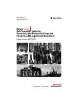
Opening the Drive Covers
(x2)
(x3)
BR1
B
R
2
D
C+
D
C
-
PE
U/T1
V/T2
W/T3
R/L1
L2
(x2)
=
=
Proper tightening
torque for reassembly
is 6 lb.-in.
Removing the Cassette
Task Description
Open the door of the power structure and disconnect the cables that
connect to the main board
Loosen screws on face of cassette
Remove the cassette
A
B
C
Removing the Side Covers
Task Description
Loosen screws on face of front cover and remove the cover
Loosen screws on side of rear cover and remove the cover
A
B
Frames 1-4
Locate the slot in the upper left corner. Slide
the locking tab up and swing the cover open.
Special hinges allow cover to move away from
drive and lay on top of adjacent drive (if
present).
Frame 5
Slide the locking tab up, loosen the right-hand
cover screw and remove.
Frame 6
Loosen two screws at bottom of drive cover.
Carefully slide bottom cover down & out.
Loosen the two screws at top of cover and
remove.
/