Page is loading ...

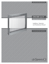
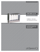
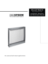
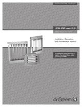
ULTRA-SORB
®
MODEL XV
Steam Dispersion Panel
Installation, Operation,
and Maintenance Manual
READ AND SAVE THESE INSTRUCTIONS
For pressurized steam applications

ii
ULTRA-SORB MODEL XV INSTALLATION, OPERATION, AND MAINTENANCE MANUAL
Table of contents
ATTENTION INSTALLER
Read this manual before installing.
Leave manual with product owner.
DriSteem technical support
800-328-4447
WARNING
Hot surface hazard
Steam humidifi cation systems have
extremely hot surfaces.
To avoid burns, allow humidifi er, steam
pipes, and dispersion assemblies to
cool before touching any part of the
system.
mc_071411_0753
MECHANICAL SPECIFICATIONS . . . . . . . . . . . . . . . . . . . . . . . . . . . . . . . . . . . . . . . . . . . . . . . . . .1
INSTALLATION
Field assembly . . . . . . . . . . . . . . . . . . . . . . . . . . . . . . . . . . . . . . . . . . 2
Piping . . . . . . . . . . . . . . . . . . . . . . . . . . . . . . . . . . . . . . . . . . . . . . . . 4
Selecting the location . . . . . . . . . . . . . . . . . . . . . . . . . . . . . . . . . . . . . . 6
Mounting and support
Installation in a cold air stream . . . . . . . . . . . . . . . . . . . . . . . . . . . 8
Placement upstream from an elbow or duct split . . . . . . . . . . . . . . . . 8
Installation above valuable equipment . . . . . . . . . . . . . . . . . . . . . . . 8
Recirculation unit . . . . . . . . . . . . . . . . . . . . . . . . . . . . . . . . . . . . . . 8
Panel support . . . . . . . . . . . . . . . . . . . . . . . . . . . . . . . . . . . . . . . . 8
Mounting in a duct . . . . . . . . . . . . . . . . . . . . . . . . . . . . . . . . . . . . 9
Mounting in an air handler . . . . . . . . . . . . . . . . . . . . . . . . . . . . . . . 9
Installation drawings
Mounting in a duct . . . . . . . . . . . . . . . . . . . . . . . . . . . . . . . . . . . 10
Mounting in an air handler . . . . . . . . . . . . . . . . . . . . . . . . . . . . . . 11
Recommendations and steam inlets . . . . . . . . . . . . . . . . . . . . . . . . . . . 12
Controls
Float switch . . . . . . . . . . . . . . . . . . . . . . . . . . . . . . . . . . . . . . . . . 13
Temperature switch . . . . . . . . . . . . . . . . . . . . . . . . . . . . . . . . . . . 13
Heat exchanger time delay . . . . . . . . . . . . . . . . . . . . . . . . . . . . . . 14
Optional header overflow P-trap water seal . . . . . . . . . . . . . . . . . . 14
Control cabinet . . . . . . . . . . . . . . . . . . . . . . . . . . . . . . . . . . . . . . 15
Wiring diagrams . . . . . . . . . . . . . . . . . . . . . . . . . . . . . . . . . . . . . . . . 16
OPERATION
Sequence of operation . . . . . . . . . . . . . . . . . . . . . . . . . . . . . . . . . . . . 18
Start-up . . . . . . . . . . . . . . . . . . . . . . . . . . . . . . . . . . . . . . . . . . . . . . 20
Performance data . . . . . . . . . . . . . . . . . . . . . . . . . . . . . . . . . . . . . . . 21
MAINTENANCE
Strainer, traps, and valves . . . . . . . . . . . . . . . . . . . . . . . . . . . . . . . . . 22
Dispersion tubes and heat exchanger . . . . . . . . . . . . . . . . . . . . . . . . . 23
Humidifier De-scaling Solution . . . . . . . . . . . . . . . . . . . . . . . . . . . . . . . 24
Replacement parts . . . . . . . . . . . . . . . . . . . . . . . . . . . . . . . . . . . . . . . 25
Troubleshooting . . . . . . . . . . . . . . . . . . . . . . . . . . . . . . . . . . . . . . . . . 26
WARRANTY . . . . . . . . . . . . . . . . . . . . . . . . . . . . . . . . . . . . . . . . . . . . . . . . . . . . . . .Back cover

1
ULTRA-SORB MODEL XV INSTALLATION, OPERATION, AND MAINTENANCE MANUAL
Mechanical specifi cations
OM-7483
mc_101410_0755
Top view
Elevation view
Blank
side view
Header
Connections
side view
A
A’
B’
C
D
B
F
F
E
G
H J
K
L
Table 1-1:
Ultra-sorb Model XV dimensions
Dimension Inches (mm)
A Unit width
15" (380 mm) min,
147" (3735 mm) max,
in 1" (25 mm) increments
A' Face width
12" (305 mm) min,
144" (3660 mm) max,
in 1" (25 mm) increments
B Unit height*
21.75" (550 mm) min,
153.75" (3905 mm) max,
in 1" (25 mm) increments
B' Face height
12" (305 mm) min,
144" (3660 mm) max,
in 1" (25 mm) increments
C Frame depth 7.2" (183 mm)
D Frame enclosure 3.9" (99 mm)
E Header enclosure 5.85" (149 mm)
F Mounting fl ange 1.5" (38 mm)
G Humidifi cation steam inlet
(internal thread)
• 1" or 2" NPT (DN25 or DN50),
determined by maximum steam
capacity
• 3" (DN80) fl ange, for humidifi cation
steam from STS humidifi er only
H Pressurized steam inlet
(internal thread)
3/4" NPT (DN20)
J Float switch,
optional header overfl ow/
access port (internal thread)
1/2" NPT (DN15)
K Pressurized condensate
outlet (internal thread)
3/4" NPT (DN20)
L Overall width
• 1" (DN25) connection, same as
dimension A;
• 2" (DN50) connection, dimension A
+ 1" (dimension A + 25 mm)
• 3" (DN80) fl ange, dimension A +
6.5" (dimension A + 165 mm)
Control cabinet See Page 15.
* Panels with unit height more than 120" (3048 mm) have two-piece
side fl anges and are shipped with brackets for easy fi eld assembly.
Panels with unit height more than 98" (2490 mm) are shipped
unassembled.
mc_091608_1500
Table 1-2:
Ultra-sorb Model XV tube capacity*
lbs/hr kg/h
43 19.5
* If face height is <17" (432 mm), consult DriSteem or see DriCalc for
the correct calculation.
FIGURE 1-1: ULTRA-SORB MODEL XV DIMENSIONS
MECHANICAL SPECIFICATIONS

2
ULTRA-SORB MODEL XV INSTALLATION, OPERATION, AND MAINTENANCE MANUAL
Field assembly
UNPACK THE DISPERSION ASSEMBLY AND LOOSE COMPONENTS
• Ultra-sorb Model XV has High-Effi ciency Tubes. These dispersion tubes are
insulated with polyvinylidene fl uoride (PVDF) insulation, which provides up
to an 85% reduction in wasted energy by signifi cantly reducing airstream
heat gain and condensate production.
• Remove shipping materials from the dispersion assembly, being careful not
to bump or scrape the white PVDF dispersion tube insulation.
• Panels taller than 60 inches (1500 mm) have wood packaging material
for fl ange support during shipping. Remove this wood before installing the
panel.
• Do not lay dispersion tubes (if shipped loose by request or by shipping
necessity) across or under anything that could compress or damage the
insulation. Compressing insulating material may reduce its R-value.
• Avoid bumping or snagging the PVDF insulation. Although PVDF is
robust, rough handling can cause tears, which could negatively impact
performance.
• Before start-up, remove the clear poly fi lm by tearing it along the
perforation. Do not use a knife or sharp object to remove the poly fi lm. Do
not remove the white PVDF insulation.
VERIFY THAT THE ORDER IS COMPLETE
Verify that all panel and piping components are included in the delivery. Check
the packing list, and see the tables on Page 25.
CAUTION
Remove clear poly fi lm; do not remove white PVDF insulation.
High-Effi ciency Tubes are sleeved in clear poly fi lm for protection during processing, shipping, and
installation. Leave the clear poly fi lm on until installation is complete so the insulation stays clean.
Equally important, remove and discard the clear poly fi lm before start-up by tearing it along the
perforations. Do not remove the white PVDF insulation.
• Keep fl ame away from the insulating material to avoid damage.
• PVDF is inherently resistant to UV light. Indirect, low-intensity UV-C light from germicidal lamps will
not cause the insulating material to degrade.
• Do not tighten mounting clamps or fasteners to any part of the dispersion tube.
mc_071211_1530
INSTALLATION

3
ULTRA-SORB MODEL XV INSTALLATION, OPERATION, AND MAINTENANCE MANUAL
Field assembly
LAY OUT THE PANEL COMPONENTS
Orient the panel components on a large, fl at working surface.
ATTACH THE FLANGES
Guide the fl anges onto the threaded studs of the header assembly, and start the
locknuts onto the threads fi nger-tight.
ATTACH THE TOP FRAME ASSEMBLY
Span the fl anges with the top frame assembly. Align the locating buttons on the
fl anges and top frame, and insert screws.
TIGHTEN THE FLANGE LOCKNUTS
Torque the eight fl ange locknuts to 16 ft-lb (22 N-m) at 100 rpm maximum
using a 7/16" deep-well socket.
INSTALL THE DISPERSION TUBES
Note: Do not remove the poly fi lm from the dispersion tubes until after the
panel is installed.
Ensure that each dispersion tube has the seal and spring in place (see
Figure 3-1). Push the dispersion tube plug end into the top frame hole to
compress the spring. Seat the seal end in the corresponding header hole
on the bottom. Rotate the dispersion tubes so the tubelets discharge steam
perpendicular to the airstream. See Figure 9-2.
Table 3-1:
Ultra-sorb Model XV components
Component Qty.
Header assembly 1
Dispersion tube Varies
Top frame assembly 1
Flanges 2
Screws 8
Flange locknuts 8
Note: These assembly instructions are for
Ultra-sorb Model XV panels shipped
unassembled by request or as required.
Panels with overall height more
than 98" (2490 mm) are shipped
unassembled.
Header
assembly
Flange
locknut
Screw
Flange
OM-7484
Top frame
assembly
Spring
Plug
Ring
Seal
Insulation
Dispersion tube
assembly
INSTALLATION
FIGURE 3-1: ULTRA-SORB MODEL XV COMPONENTS

4
ULTRA-SORB MODEL XV INSTALLATION, OPERATION, AND MAINTENANCE MANUAL
Piping
OM-7656b
From pressurized steam source
Electric modulating steam valve
To condensate
return main
On-off valve
Inlet
strainer
F&T trap
To condensate return main
Standard trap piping
Ultra-sorb Model XV
steam dispersion panel
Note: Dashed lines indicate provided by installer.
Float switch
14" (355 mm)
F&T trap
clearance
F&T trap
mc_051811_1025
OM-7536
Standard trap piping
mc_101410_0800
From pressurized steam source
Pneumatic modulating steam valve
To condensate return main
On-off valve
Inlet
strainer
F&T trap
To condensate return main
Ultra-sorb Model XV
steam dispersion panel
Note: Dashed lines indicate provided by installer.
Temperature switch sensor (install
as close to outlet as possible)
F&T trap
See alternate trap piping for minimum
clearance in Figure 4-3.
INSTALLATION
Install inlet strainer (same size as
valve, or larger than valve) within
3' (1 m) of Ultra-sorb
Valve
From pressurized
steam source
DC-1097
mc_101410_0810
14"
(355 mm) F&T
trap clearance
FIGURE 4-1: ULTRA-SORB MODEL XV PIPING COMPONENTS (WITH FLOAT SWITCH),
PRESSURIZED STEAM SOURCE
FIGURE 4-2: ULTRA-SORB STRAINER
FIGURE 4-3: ULTRA-SORB MODEL XV PIPING COMPONENTS (WITH TEMPERATURE
SWITCH), PRESSURIZED STEAM SOURCE

5
ULTRA-SORB MODEL XV INSTALLATION, OPERATION, AND MAINTENANCE MANUAL
INSTALLATION
Note: Dashed lines indicate provided by installer.
DM-11136b
OM-7654-components
Connection end of header
(see inset below)
Connection end of header
Humidifi cation steam
from STS humidifi er
Pressurized condensate to return main
On-off
valve
Inlet
strainer
F&T trap
To condensate return main
Float switch
F&T trap
From pressurized steam source
Dispersion tube
Header
From pressurized
steam source
Electric
steam valve
Insulated copper
steam supply tubing
STS humidifi er
Open drain
(temper to local code)
Drane-kooler™
Cold fi ll water
Isolation valve (by others)
Pressurized steam to heat exchanger
Note: Tubing union shown at steam connection. For STS humidifi er,
connection may also be 3" (DN80) fl ange.
Steam to heat exchanger from pressurized steam source,
humidifi cation steam from STS humidifi er
mc_060911_1230
Piping
OM-7655-sts
Alternate trap piping for minimal clearance
6" (152 mm) F&T trap clearance
FIGURE 5-1: ULTRA-SORB MODEL XV PIPING WITH STS HUMIDIFIER

6
ULTRA-SORB MODEL XV INSTALLATION, OPERATION, AND MAINTENANCE MANUAL
Outside air
Relief air
Preheat coil
Motorized
air dampers
Supply airfl ow
Filters
Economizer
control device
Heating coil
Cooling coil
8' to 12' (2.4 to 3.7 m)
Duct high limit humidity control
for dispersion locations A, B
Airfl ow proving switch
Airfl ow proving switch
Duct high limit humidity control
for dispersion location C
Return airfl ow
8' to 12' (2.4 to 3.7 m)
3' to 5' (1 to 1.5 m)
Fan
ABD
C
Exterior
building
wall
DC-1081
mc_092507_1530
Selecting the location
INSTALLATION
FIGURE 6-1: PLACING A DISPERSION ASSEMBLY IN AN AIR HANDLING UNIT

7
ULTRA-SORB MODEL XV INSTALLATION, OPERATION, AND MAINTENANCE MANUAL
• Install the Ultra-sorb panel in a location where discharged water vapor will
be absorbed by the airstream.
• In general, place the Ultra-sorb panel where the air temperature is capable
of absorbing discharged steam without causing condensation at or after the
unit. This will normally be downstream of the heating coil where the air is
warmest.
• Do not place the Ultra-sorb panel in an outside air intake unless the air is
tempered with a preheat coil.
• Do not place the Ultra-sorb panel near the entrance of a high-effi ciency
fi lter. The fi lter will remove visible moisture and become waterlogged. See
the Caution “Installing Ultra-sorb upstream from fi lter media” on Page 21.
• Do not place the Ultra-sorb panel where discharged visible mist will
impinge directly on a metal surface.
mc_071111_1710
PLACEMENT IN AN AIR HANDLING UNIT
• Location A is the best choice. Installing downstream of heating and cooling
coils provides laminar fl ow through the dispersion unit; plus, the heated air
provides an environment for best absorption.
• Location B is the second-best choice. However, in change-over periods, the
cooling coil will eliminate some moisture for humidifi cation.
• Location C is the third-best choice. Air leaving a fan is usually very turbulent
and can cause vapor to not absorb at the expected non-wetting distance.
Allow for more distance if installing downstream of a fan.
• Location D is the poorest choice. The cooler air at this location requires an
increased non-wetting distance.
mc_062111_0715
Selecting the location
INSTALLATION
DETERMINE HUMIDIFIER PLACEMENT
Dispersed steam must be absorbed into the airfl ow before it comes in
contact with duct elbows, fans, vanes, fi lters, or any object that can cause
condensation and dripping.

8
ULTRA-SORB MODEL XV INSTALLATION, OPERATION, AND MAINTENANCE MANUAL
Mounting and support
Elbow
Duct
Airfl ow
Airfl ow
Ultra-sorb
Ultra-sorb
Duct split
Non-wetting
distance
OM-178
INSTALLATION
Ultra-sorb
Airfl ow
Drip pan
Ceiling line
Vapor absorption
area
* This length of duct should have sealed seams
and should be at least three times the height
of the Ultra-sorb panel.
OM-198
2" (50 mm)
OM-197
Cold
air
fl ow
Ultra-sorb
Extended trails of
fog may develop
High limit duct humidistat 10' to 15'
(3 to 4.5 m) downstream from Ultra-sorb
mc_101410_0955
mc_052411_0830
INSTALLATION IN A COLD AIR STREAM
When a humidifi er is installed in a duct that will carry cold air, determine the
dew point temperature. If the psychrometric chart reveals that saturation may
occur, protection should be provided. A high-limit humidistat or thermostat set
to cut off the humidifi er at a safe temperature can be used for this purpose. See
Figure 8-1.
PLACEMENT UPSTREAM FROM AN ELBOW OR DUCT SPLIT
Due to Ultra-sorb's rapid steam absorption performance, installation upstream
from elbows or duct splits can be done with confi dence. See Figure 8-2.
INSTALLATION ABOVE VALUABLE EQUIPMENT
Water piping and humidifi ers should not be installed above expensive
equipment. A condensing or leaking water pipe or other accidental water
spillage could cause serious damage to the equipment below. When such
an installation cannot be avoided, install a galvanized drip pan under the
humidifi er piping, valve, etc. to catch and drain away unintended water. See
Figure 8-3.
See also “Optional header overfl ow P-trap water seal” on Page 14.
RECIRCULATION UNIT
In applications where no duct system exists, or if the air is too cool for proper
humidity absorption, a recirculation fan can be used. The fan circulates room
temperature air across the humidifi er and discharges humidifi ed air into the
space. Select the air discharge point carefully to avoid condensation on
building or equipment surfaces. See Figure 8-4.
PANEL SUPPORT
The duct or air handler section and Ultra-sorb panel must be properly
supported to carry the weight of the assembly. The weight of the piping must
be supported by the building structure rather than by the Ultra-sorb unit.
Otherwise, the weight may impose stress on the connections, causing them to
fracture and leak.
mc_071311_1540
Ceiling line
Ultra-sorb
Airfl ow
Blower
Vapor
absorption
area
*
* This duct length should have sealed
seams and should be at least three
times the published non-wetting
distance.
OM-179
mc_071311_1545
Pipe to drain size as required
FIGURE 8-1:
INSTALLATION IN A COLD AIR STREAM
FIGURE 8-4: RECIRCULATION UNIT
FIGURE 8-2: UPSTREAM PLACEMENT
FIGURE 8-3:
INSTALLATION ABOVE SENSITIVE AREAS

9
ULTRA-SORB MODEL XV INSTALLATION, OPERATION, AND MAINTENANCE MANUAL
Mounting and support
Dispersion tube orientation
Verify that the steam discharge tubelets are
perpendicular to the airstream (see Figure 9-1).
The spring-loaded dispersion tubes easily rotate
for proper orientation.
Airfl ow
Tubelet Dispersion tube
Airfl ow
OM-150a
Duct smoke detector
Do not install a duct smoke detector
downstream from the Ultra-sorb panel. If
downstream installation is required, install it far
enough from the Ultra-sorb panel to avoid false
alarms.
OM-7482
Top outside corners
Four inside corners
Perimeter of top frame along duct fl ange
Both sides of cover seam
mc_101410_0845
INSTALLATION
Ultra-sorb Model XV heat exchanger must use steam from pressurized steam
source only. Humidifi cation steam can be from pressurized steam source or STS
steam-to-steam humidifi er.
Ultra-sorb Model XV must be installed in horizontal airfl ows only.
To avoid puncturing the header, screws and drill bits must not penetrate more
than 3/4" (20 mm) into the header assembly. See Figure 10-1 for allowable
drill and screw locations.
MOUNTING IN A DUCT
Mounting fl anges on both sides of the unit and the header and frame can
be used as mounting surfaces (see Figure 10-1). A matching fl ange or metal
frame is required on the ductwork for connection to the Ultra-sorb fl anges. The
recommended fastener is a #12 self-drilling and tapping screw 3/4" (20 mm)
long, spacing not to exceed 12" (305 mm). If an angle-iron frame is provided
on the duct section, a longer screw may be required.
MOUNTING IN AN AIR HANDLER
Metal support frames should be anchored to the air handler casing.
Recommended fasteners for mounting the Ultra-sorb to a metal support frame
are 1/4 - 20 nuts and bolts or #12 self drilling and tapping screws. Due to
possible forces exerted on this application, fastener spacing should not exceed
of 6" (150 mm).
mc_101410_0935
Ultra-sorb panels that
penetrate a duct section
must be sealed with
HVAC caulking or a
similar weather sealant
to prevent air leakage.
FIGURE 9-2: PREVENTING DUCT STATIC PRESSURE LOSS
FIGURE 9-1:
DISPERSION TUBE ORIENTATION

10
ULTRA-SORB MODEL XV INSTALLATION, OPERATION, AND MAINTENANCE MANUAL
Installation drawings:
INSTALLATION
OM-7490
Attach duct fl ange to top frame assembly
1/2" (13 mm)
Attach duct fl anges to 1.5"
(38 mm) mounting fl anges
Attach duct fl ange to
header assembly
Screws OK
3/4" (20 mm) max length (See Note 7)
Screws OK
No screws
Notes:
1. See Figures 12-1 and 12-2 for trap clearance alternatives.
2. Steam supply line to unit and piping are not included.
3. Dispersion tubes are available on 3", 6", 9" and 12" (15, 150, 225, and 300 mm) centers
4. Ultra-sorb humidifi ers will be assembled, crated, and shipped intact in all sizes up to 98" (2490 mm) overall height. Any Ultra-sorb can be shipped
unassembled by request, requiring fi eld assembly.
5. Standard sizes are 12" x 12" up to 144" x 144" in 1" increments (305 x 305 mm up to 3660 x 3660 mm in 25 mm increments). Larger sizes are
available.
6. Install the panel level. If slope cannot be avoided, ensure that the slope is toward the drain end of the panel.
7. To avoid damaging the header and heat exchanger, drill or screw through the header assembly only where shown.
Screws and drill bits must not penetrate more than 3/4" (20 mm) into the header assembly. Recommended fasteners for mounting the Ultra-sorb to
a metal support frame are 1/4–20 nuts and bolts or #12 self drilling and tapping screws.
No screws through bottom of
header assembly
No screws through top of header
assembly
No screws through end of
header assembly
No screws through
end of header
assembly
Screws OK
Screws OK
mc_101310_1030
Mounting in a duct
FIGURE 10-1: ULTRA-SORB MODEL XV IN A DUCT (HORIZONTAL AIRFLOW ONLY)
1/2" (13 mm)

11
ULTRA-SORB MODEL XV INSTALLATION, OPERATION, AND MAINTENANCE MANUAL
Notes:
1. Dashed lines indicate provided by installer.
2. See Figures 12-1 and 12-2 for trap clearance alternatives.
3. Steam supply line to unit and piping are not included.
4. Dispersion tubes are available on 3", 6", 9" and 12" (15, 150, 225, and 300 mm) centers.
5. Ultra-sorb humidifi ers will be assembled, crated, and shipped intact in all sizes up to 98" (2490 mm) overall height. Any Ultra-sorb can be shipped
unassembled by request, requiring fi eld assembly.
6. Standard sizes are 12" x 12" up to 144" x 144" in 1" increments (305 x 305 mm up to 3660 x 3660 mm in 25 mm increments).
Larger sizes are available.
7. Heat exchanger requires 5 psig (35 kPa) minimum steam pressure.
Mounting in an air handling unit
• Metal support frames should be anchored to the air handler casing.
• To avoid damaging the header and heat exchanger, drill or screw through the header assembly only where shown in Figure 10-1. Screws and drill
bits must not penetrate more than 3/4" (20 mm) into the header assembly.
• Recommended fasteners for mounting the Ultra-sorb to a metal support frame are 1/4–20 nuts and bolts or #12 self drilling and tapping screws.
• Due to possible forces exerted on this application, DriSteem recommends fastener spacing not to exceed 6" (150 mm).
• When Ultra-sorb Model XV is installed in bypass air applications additional bracing is advised for the unsupported side(s).
• Install the panel level. If slope cannot be avoided, ensure that the slope is toward the drain end of the panel.
Connection end
of header
Humidifi cation steam
inlet:
• 1" or 2" NPT
(DN25 or DN50),
determined by
maximum steam
capacity
• 3" (DN80) fl ange,
STS humidifi er only
Pressurized boiler steam inlet
(3/4" NPT, internal thread)
Pressurized condensate outlet
(3/4" NPT, internal thread)
Float switch, optional header overfl ow/
access port (1/2" NPT, internal thread)
Tubelets perpendicular to airfl ow
Humidifi cation steam to header
AHU wall
Pressurized condensate out to return main
Steam from pressurized steam
source to heat exchanger
Header
CAUTION
Use a backup wrench
Use a backup wrench on all
plumbing connections. Failure to
use a backup wrench could cause
damage to the Ultra-sorb Model XV.
mc_101310_1020
INSTALLATION
Mounting in an air handlerInstallation drawings:
FIGURE 11-1: ULTRA-SORB MODEL XV IN AN AIR HANDLER (HORIZONTAL AIRFLOW ONLY)
OM-7657a
Coil
height
AHU
height
Coil width
AHU width

12
ULTRA-SORB MODEL XV INSTALLATION, OPERATION, AND MAINTENANCE MANUAL
Recommendations and steam inlets
To condensate
return main
F&T trap
Standard trap piping
14" (355 mm)
F&T trap
clearance
mc_051811_1025
Alternate trap piping for
minimal clearance
6" (152 mm) F&T trap clearance
OM-7655
mc_051811_1026
Note: Dashed lines indicate provided by
installer.
Note: Dashed lines indicate provided by
installer.
RECOMMENDATIONS
Trapping
• Low pressure, up to 15 psi (103 kPa) — fl oat and thermostatic (F&T)
trap (Figures 12-1 and 12-2)
• High pressure, more than 15 psi (103 kPa) — inverted bucket trap
(Figure 12-3)
• Lifting condensate — inverted bucket trap (Figure 12-3)
Driest steam
To ensure driest steam, take humidifi er steam off the top of the steam main
(not the side or bottom).
Airfl ow proving switch
An airfl ow proving switch is recommended to prevent humidifi cation steam
from entering the header if air is not moving in the duct.
High limit humidistat
To prevent over saturation when duct air is cooler than 70 °F (21 °C), a
high limit (duct mounted) humidistat is recommended (Figure 6-1). Mount it
10' to 15' (3 to 4.5 m) downstream from the Ultra-sorb panel, and set it at
80 to 90% RH.
HEAT EXCHANGER PRESSURIZED BOILER STEAM INLET
Steam pressure for steam entering the heat exchanger must be least 5 psig
(35 kPa) to vaporize condensate in the header.
HUMIDIFICATION STEAM INLET
Humidifi cation steam entering the header can be from a modulating steam
valve or from an STS humidifi er. See interconnecting piping requirements for
STS humidifi er applications in Table 13-1.
mc_061511_1235
INSTALLATION
Steam valve
DM-11554
mc_062111_0900
Elevated condensate
return main
Strainer
Inverted bucket trap
Check valve (by others)
Typical stand (by others)
Housekeeping pad / AHU rail
Integral heat exchanger
• Ultra-sorb Model XV employs an integral
heat exchanger to pressurize and lift
condensate up to 12" per psi (300 mm
per 6.9 kPa) of steam pressure.
• Steam pressure entering the heat exchanger
must be at least 5 psig (35 kPa).
• Condensate may be piped to the condensate
return main.
OM-7656_close-up
FIGURE 12-3: LIFTING CONDENSATE WITH ULTRA-SORB MODEL XV
FIGURE 12-1: ULTRA-SORB MODEL XV
F&T TRAP DIMENSIONS
FIGURE 12-2: ULTRA-SORB MODEL XV
ALTERNATE PIPING

13
ULTRA-SORB MODEL XV INSTALLATION, OPERATION, AND MAINTENANCE MANUAL
Controls
FLOAT SWITCH
Under normal conditions the fl oat switch (for use with an electric steam valve)
in the Ultra-sorb Model XV header is closed, and the modulating steam valve
or STS humidifi er operates according to the humidifi cation control system’s call
for humidity.
• See “Float switch, for use with electric steam valve” on Page 19.
• See fl oat switch instructions in Step 1 on Page 24. These instructions must
be followed for the fl oat switch to function properly.
• See the wiring diagram in Figure 16-1.
mc_051711_1120
Table 13-1:
Maximum steam carrying capacity and length of interconnecting steam tubing
1
Copper or stainless steel tubing, nonpressurized steam from STS humidifi er
Tube size Maximum capacity
2
Maximum
developed length
3
inches DN lbs/hr kg/h ft m
2 50 220 100 30 9
3
4
80
4
450 204 80 24
1.
Based on total maximum pressure drop in tubing of 5" wc (1250 Pa).
2. Insulate tubing to minimize loss of capacity and effi ciency.
3. Developed length of tubing equals measured length plus 50% of measured length, to account
for fi ttings.
Longer tubing lengths are possible at capacities lower than listed maximums. Consult factory.
4. Requires fl ange connection.
mc_091410_1050-XV
INSTALLATION
TEMPERATURE SWITCH
Install the temperature switch (Figure 19-1) to prevent the header from fl ooding
with condensate if the heat exchanger cools, such as if the condensate return
main becomes fl ooded or the trap fails closed. DriSteem's temperature switch
is a temperature-actuated make-break switch. The temperature at which it
switches is adjustable and should be set at 210 °F (99 °C).
• Install the sensing element of the device in the condensate return piping
between the Ultra-sorb heat exchanger outlet and the inlet to the steam trap,
as shown in Figure 19-1. Include a tee with a 1/2" (DN15) pipe thread
opening to receive the sensing element. When steam surrounds the sensing
element, the switch will “make,” allowing the humidifi er valve to open.
• Install all wiring according to national and local electrical codes, and size
transformer VA to load VA.
• When using a temperature switch to control the on-off heat exchanger
valve, follow the special wiring instructions supplied with the modulating
humidifi cation-steam control valve.
• See the wiring diagram in Figure 17-1.
mc_100610_1035

14
ULTRA-SORB MODEL XV INSTALLATION, OPERATION, AND MAINTENANCE MANUAL
Controls
INSTALLATION
Note: After the water seal, run a 1½" (DN40)
drain line to an open drain with a 1"
(25 mm) air gap.
OM-7493
Optional P-trap overfl ow
water seal (if no fl oat
switch)
Connection end of header
1.25" (32 mm) rise
OM-7
OM-7
493
493
10.75" (273 mm)
Fill cap
mc_101410_0811
OPTIONAL HEADER OVERFLOW P-TRAP WATER SEAL
Ultra-sorb Model XV is designed to vaporize the condensate generated in a
properly designed, installed, operated, and maintained system. An optional,
fail-safe header overfl ow installation (Figure 14-1) is recommended if any of
the following are true:
• No fl oat switch.
• Operating parameters exceed design criteria.
• Boiler chemicals are causing heavy material deposition on heat exchanger.
• System overfl ow prevention is critical.
• Application requires the tallest dispersion tubes, the closest tube spacing,
and the lowest allowable heat exchanger steam pressures.
• Operator intervention could result in improper system settings.
Before operating the Ultra-sorb, and after extended shutdown periods, prime
the P-trap with about 1 cup (200 ml) of water. During normal operation, little
or no condensate is available to the overfl ow. As such, a water seal cannot
be assured via condensate alone. Without a water seal, the header overfl ow
P-trap, if one is installed, might allow air to be drawn into the duct or steam to
blow through the P-trap.
Do not feed the P-trap with a water source to maintain prime, as this will force
water into the header.
mc_052311_1135
HEAT EXCHANGER TIME DELAY
Systems that stop humidifying for extended periods of time may have two
reasons for a time delay: To conserve energy, and to dry the header and
remove standing water that might allow for microbe growth.
To dry the header, pressurized steam can be set to fl ow through the heat
exchanger for a set amount of time after humidifi cation steam stops. This time
delay can be set through the building management system (BMS) or confi gured
independent from the BMS. See the wiring diagram included with the on-off
valve.
• Setting the heat exchanger to remain on for at least 1/2 hour after
humidifying stops will be adequate time to ensure complete dry-out of the
dispersion system.
• For systems that run constantly (all day, every day, all year), there is no
need to set a time delay.
• See the wiring diagrams on Pages 16 and 17.
mc_100610_1036
FIGURE 14-1: ULTRA-SORB MODEL XV
OPTIONAL HEADER OVERFLOW P-TRAP
WATER SEAL
12" (305 mm) seal

15
ULTRA-SORB MODEL XV INSTALLATION, OPERATION, AND MAINTENANCE MANUAL
12" (305 mm)
12" (305 mm)
6" (152 mm)
OM-7533
Notes:
• Electrical power requirements: 120 VAC, 0.2 Amps, or 240 VAC, 0.1
Amps
• Components are 24 VAC, powered by a transformer in the control
cabinet. A pneumatic interface is available for systems ordered with
pneumatic control.
• Maximum distance from control cabinet to Ultra-sorb Model XV is 50’
(15 m).
See control cabinet fi eld wiring diagrams on Pages 16 and 17.
Controls
mc_101410_0820
INSTALLATION
FIGURE 15-1: ULTRA-SORB MODEL XV CONTROL CABINET

16
ULTRA-SORB MODEL XV INSTALLATION, OPERATION, AND MAINTENANCE MANUAL
Wiring diagrams
INSTALLATION
XV-1
External connections
FIGURE 16-1: ULTRA-SORB MODEL XV CONTROL CABINET FIELD WIRING, ELECTRIC MODULATING STEAM VALVE

17
ULTRA-SORB MODEL XV INSTALLATION, OPERATION, AND MAINTENANCE MANUAL
Wiring diagrams
INSTALLATION
External connections
Pneumatic supply by others, 0-20 psi (0-138 kPa)
mc_052010_0600
DISP-3-C
FIGURE 17-1: ULTRA-SORB MODEL XV CONTROL CABINET FIELD WIRING, PNEUMATIC MODULATING STEAM VALVE

18
ULTRA-SORB MODEL XV INSTALLATION, OPERATION, AND MAINTENANCE MANUAL
Sequence of operation
OM-7656a
From pressurized
steam source
To condensate return main
To condensate return main
1
2
6
5a
5b
Ultra-sorb Model XV panel Dispersion tube
OM-7481
3
4
4a
4b
4c
4d
mc_033010_1150
Note: Dashed lines indicate provided by installer.
A
F&T trap
Inlet
strainer
Electric modulating
steam valve
2
OM-7654-inlets
Humidifi cation
steam from STS
steam-to-steam
humidifi er
Note: Dashed lines indicate
provided by installer.
From
pressurized
steam source
OPERATION
1. HEAT EXCHANGER ON-OFF SOLENOID VALVE
See Figure 18-2.
Upon a call for humidity, the heat exchanger on-off solenoid valve opens,
and pressurized steam fl ows through the heat exchanger, out the trap (A),
and to the condensate return main.
2. STEAM SUPPLY INLET
Humidifi cation steam from the modulating steam valve (Figure 18-2) or STS
humidifi er (Figure 18-1) passes through the steam supply inlet into the Ultra-
sorb header.
3. HEADER
Humidifi cation steam fl ows through the insulated header, up the High-
Effi ciency Tubes, and into the airstream.
4. HIGH-EFFICIENCY TUBES
Calibrated thermal-resin tubelets (4a) allow only the driest steam to exit
into the airstream. Dispersion tube insulation (4b) provides up to an 85%
reduction in wasted energy by signifi cantly reducing airstream heat gain
and condensate production. Dispersion tube spring-ends (4c) provide rapid
tube removal and installation while ensuring tight seals (4d) between the
header and tubes.
FIGURE 18-1: ULTRA-SORB MODEL XV
WITH STS; STEAM INLETS DETAILED
FIGURE 18-2: ULTRA-SORB MODEL XV COMPONENTS, PRESSURIZED STEAM SOURCE
/