Page is loading ...

VAPORSTREAM
®
Electric Humidifier
Installation, Operation,
and Maintenance Manual
READ AND SAVE THESE INSTRUCTIONS

ii
VAPORSTREAM INSTALLATION, OPERATION, AND MAINTENANCE MANUAL
Warnings and cautions
WARNING
CAUTION
Indicates a hazardous situation that could result in death or
serious injury if instructions are not followed.
Indicates a hazardous situation that could result in damage to or
destruction of property if instructions are not followed.
mc_051508_1145
WARNINGS AND CAUTIONS
WARNING
Attention installer
Read this manual before installing, and leave this manual with product owner. This product must be installed by qualifi ed
HVAC and electrical contractors and in compliance with local, state, federal, and governing codes. Improper installation
can cause property damage, severe personal injury, or death as a result of electric shock, burns, or fi re.
DriSteem Technical Support: 800-328-4447
Read all warnings and instructions
Read this manual before performing service or maintenance procedures on any part of the system. Failure to follow all
warnings and instructions could produce the hazardous situations described, resulting in property damage, personal injury,
or death.
Failure to follow the instructions in this manual can cause moisture to accumulate, which can cause bacteria and mold
growth or dripping water into building spaces. Dripping water can cause property damage; bacteria and mold growth can
cause illness.
mc_011909_1215
Hot surfaces and hot water
This steam humidifi cation system has extremely hot surfaces. Water in tank, steam hose and tubes, and dispersion
assemblies can be as hot as 212 °F (100 °C). Discharged steam is not visible. Contact with hot surfaces, discharged hot
water, or air into which steam has been discharged can cause severe personal injury. To avoid severe burns, follow the
cool-down procedure in this manual before performing service or maintenance procedures on any part of the system.
mc_011909_1130
Warnings and cautions

iii
VAPORSTREAM INSTALLATION, OPERATION, AND MAINTENANCE MANUAL
Warnings and cautions
Warnings and Cautions
WARNING
Disconnect electrical power
Disconnect electrical power before installing supply wiring or performing service or maintenance procedures on any
part of the humidifi cation system. Failure to disconnect electrical power could result in fi re, electrical shock, and other
hazardous conditions. These hazardous conditions could cause property damage, personal injury, or death.
Contact with energized circuits can cause property damage, severe personal injury, or death as a result of electrical
shock or fi re. Do not open control cabinet or remove heater terminal or subpanel access panels until electrical power is
disconnected.
Follow the shutdown procedure in this manual before performing service or maintenance procedures on any part of the
system.
mc_011909_1135
Electric shock hazard
If the humidifi er starts up responding to a call for humidity during maintenance, severe bodily injury or death from electric
shock could occur. To prevent such start-up, follow the procedure below before performing service or maintenance
procedures on this humidifi er (after the tank has cooled down and drained):
1. Use Vapor-logic
®
keypad/display to change control mode to Standby.
2. Shut off all electrical power to humidifi er using fi eld-installed fused disconnect, and lock all power disconnect switches in
OFF position.
3. Close fi eld-installed manual water supply shut-off valve.
mc_050808_1540
CAUTION
Hot discharge water
Discharge water can be as hot as 212 °F (100 °C) and can damage the drain plumbing.
To prevent such damage from humidifi ers without water tempering, allow the tank to cool before draining.
Humidifi ers equipped with a water tempering device such as a DriSteem Drane-kooler need fresh make-up water in order to
function properly. Make sure the water supply to the water tempering device remains open during draining.
Excessive supply water pressure
Supply water pressure greater than 80 psi (550 kPa) can cause the humidifi er to overfl ow.
mc_030910_1440

iv
VAPORSTREAM INSTALLATION, OPERATION, AND MAINTENANCE MANUAL
Table of contents
ATTENTION INSTALLER
Read this manual before installing.
Leave manual with product owner.
DriSteem
®
Technical Support
800-328-4447
WHERE TO FIND MORE INFORMATION
Our web site:
The following documents are available on our
web site: www.dristeem.com
• Catalogs
– Vaporstream
– Ultra-sorb
• Installation, Operation, and Maintenance
manuals (IOM)
– Ultra-sorb
– Vapor-logic controller (includes
humidifier operation and troubleshooting)
• DriSteem Humidification System Design
Guide (includes steam loss tables and
general humidification information)
DriCalc
®
:
DriCalc, our software for humidifi cation system
sizing and selection, can be ordered at our
web site. Also in DriCalc:
• Library of installation guides
• Dispersion and sensor placement in ducts
and air handlers
• Vertical airflows
Call us at 800-328-4447
Obtaining documents from our web site or
from DriCalc is the quickest way to view our
literature, or we will be happy to mail literature
to you.
WARNINGS AND CAUTIONS . . . . . . . . . . . . . . . . . . . . . . . . . . . . . . . . . . . . . . . . . . . . . . . . . . .
ii
OVERVIEW. . . . . . . . . . . . . . . . . . . . . . . . . . . . . . . . . . . . . . . . . . . . . . . . . . . . . . . . . . . . . . . . .2
SPECIFICATIONS . . . . . . . . . . . . . . . . . . . . . . . . . . . . . . . . . . . . . . . . . . . . . . . . . . . . . . . . . . . . .4
North American models, capacities, and electrical specifications . . . . . . . 4
Dimensions . . . . . . . . . . . . . . . . . . . . . . . . . . . . . . . . . . . . . . . . . . . . . 6
Weights and cabinet sizes . . . . . . . . . . . . . . . . . . . . . . . . . . . . . . . . . . 8
Selecting a location . . . . . . . . . . . . . . . . . . . . . . . . . . . . . . . . . . . . . . . 9
INSTALLATION . . . . . . . . . . . . . . . . . . . . . . . . . . . . . . . . . . . . . . . . . . . . . . . . . . . . . . . . . . . . . .9
Mounting: . . . . . . . . . . . . . . . . . . . . . . . . . . . . . . . . . . . . . . . . . . . . . 10
Support legs . . . . . . . . . . . . . . . . . . . . . . . . . . . . . . . . . . . . . . . . 10
Overview . . . . . . . . . . . . . . . . . . . . . . . . . . . . . . . . . . . . . . . . . . 10
Trapeze hanger . . . . . . . . . . . . . . . . . . . . . . . . . . . . . . . . . . . . . . 11
Wall brackets . . . . . . . . . . . . . . . . . . . . . . . . . . . . . . . . . . . . . . . 12
Weather cover . . . . . . . . . . . . . . . . . . . . . . . . . . . . . . . . . . . . . . . . . 13
Outdoor Enclosure: . . . . . . . . . . . . . . . . . . . . . . . . . . . . . . . . . . . . . . 15
Overview . . . . . . . . . . . . . . . . . . . . . . . . . . . . . . . . . . . . . . . . . . 15
Weights, electrical specifications, and connection sizes . . . . . . . . . . 17
Operating temperatures . . . . . . . . . . . . . . . . . . . . . . . . . . . . . . . . 18
Mounting . . . . . . . . . . . . . . . . . . . . . . . . . . . . . . . . . . . . . . . . . . 19
Operation . . . . . . . . . . . . . . . . . . . . . . . . . . . . . . . . . . . . . . . . . . 22
Piping: . . . . . . . . . . . . . . . . . . . . . . . . . . . . . . . . . . . . . . . . . . . . . . . 23
Overview, tap/softened water . . . . . . . . . . . . . . . . . . . . . . . . . . . 23
Overview, RO/DI water option . . . . . . . . . . . . . . . . . . . . . . . . . . . 24
Drain . . . . . . . . . . . . . . . . . . . . . . . . . . . . . . . . . . . . . . . . . . . . . 25
Water supply . . . . . . . . . . . . . . . . . . . . . . . . . . . . . . . . . . . . . . . 28
Wiring: . . . . . . . . . . . . . . . . . . . . . . . . . . . . . . . . . . . . . . . . . . . . . . 30
Overview . . . . . . . . . . . . . . . . . . . . . . . . . . . . . . . . . . . . . . . . . . 30
European requirements . . . . . . . . . . . . . . . . . . . . . . . . . . . . . . . . . 32
Preventing electrical noise . . . . . . . . . . . . . . . . . . . . . . . . . . . . . . . 33
Control wiring and grounding requirements . . . . . . . . . . . . . . . . . . 34
Sensor placement . . . . . . . . . . . . . . . . . . . . . . . . . . . . . . . . . . . . . . . 35
Dispersion: . . . . . . . . . . . . . . . . . . . . . . . . . . . . . . . . . . . . . . . . . . . . 36
Selecting the dispersion assembly location . . . . . . . . . . . . . . . . . . . 36
Interconnecting piping requirements . . . . . . . . . . . . . . . . . . . . . . . . 37
Steam outlet connections . . . . . . . . . . . . . . . . . . . . . . . . . . . . . . . 39
Drip tee installation . . . . . . . . . . . . . . . . . . . . . . . . . . . . . . . . . . . 41
Single tube and multiple tube . . . . . . . . . . . . . . . . . . . . . . . . . . . . 42
Rapid-sorb . . . . . . . . . . . . . . . . . . . . . . . . . . . . . . . . . . . . . . . . . 47
Ultra-sorb . . . . . . . . . . . . . . . . . . . . . . . . . . . . . . . . . . . . . . . . . . 53
SDU-I and SDU-E . . . . . . . . . . . . . . . . . . . . . . . . . . . . . . . . . . . . . 54
Area-type fan . . . . . . . . . . . . . . . . . . . . . . . . . . . . . . . . . . . . . . . 58

1
VAPORSTREAM INSTALLATION, OPERATION, AND MAINTENANCE MANUAL
Table of contents
Keypad/display and troubleshooting
The Vapor-logic Installation and Operation
Manual, which was shipped with your
humidifi er, is a comprehensive operation
manual. Refer to it for information about using
the keypad/display and Web interface, and for
troubleshooting information.
Download DriSteem literature
Most DriSteem product manuals can be
downloaded, printed, and ordered from our
web site: www.dristeem.com
mc_052410_1335
OPERATION . . . . . . . . . . . . . . . . . . . . . . . . . . . . . . . . . . . . . . . . . . . . . . . . . . . . . . . . . . . . . . 60
Start-up procedure . . . . . . . . . . . . . . . . . . . . . . . . . . . . . . . . . . . . . . . 60
Start-up checklist . . . . . . . . . . . . . . . . . . . . . . . . . . . . . . . . . . . . . . . . 61
MAINTENANCE . . . . . . . . . . . . . . . . . . . . . . . . . . . . . . . . . . . . . . . . . . . . . . . . . . . . . . . . . . . 62
Tap/softened water: . . . . . . . . . . . . . . . . . . . . . . . . . . . . . . . . . . . . . 62
Water quality and skim duration . . . . . . . . . . . . . . . . . . . . . . . . . . 62
Cool-down procedure . . . . . . . . . . . . . . . . . . . . . . . . . . . . . . . . . 63
Inspection and maintenance . . . . . . . . . . . . . . . . . . . . . . . . . . . . . 64
RO/DI water option: . . . . . . . . . . . . . . . . . . . . . . . . . . . . . . . . . . . . . 66
Cool-down procedure . . . . . . . . . . . . . . . . . . . . . . . . . . . . . . . . . 66
Inspection and maintenance . . . . . . . . . . . . . . . . . . . . . . . . . . . . . 67
Outdoor Enclosure . . . . . . . . . . . . . . . . . . . . . . . . . . . . . . . . . . . . . . . 68
Humidifier . . . . . . . . . . . . . . . . . . . . . . . . . . . . . . . . . . . . . . . . . . . . 69
REPLACEMENT PARTS . . . . . . . . . . . . . . . . . . . . . . . . . . . . . . . . . . . . . . . . . . . . . . . . . . . . . . . 69
Control cabinet . . . . . . . . . . . . . . . . . . . . . . . . . . . . . . . . . . . . . . . . . 71
SDU-I . . . . . . . . . . . . . . . . . . . . . . . . . . . . . . . . . . . . . . . . . . . . . . . . 73
SDU-E . . . . . . . . . . . . . . . . . . . . . . . . . . . . . . . . . . . . . . . . . . . . . . . 74
Outdoor Enclosure . . . . . . . . . . . . . . . . . . . . . . . . . . . . . . . . . . . . . . . 75
WARRANTY . . . . . . . . . . . . . . . . . . . . . . . . . . . . . . . . . . . . . . . . . . . . . . . . . . . . . . . . . . . . . . 76

2
VAPORSTREAM INSTALLATION, OPERATION, AND MAINTENANCE MANUAL
FIGURE 2-1: VAPORSTREAM SYSTEM EXAMPLE, TAP/SOFTENED WATER
Product overview
TAP/SOFTENED WATER
Vaporstream humidifi ers with tap/softened water (shown above) use electricity
to heat tap or softened fi ll water into steam for humidifi cation. A conductivity
probe monitors the water level; therefore, water conductivity must be at least
30 μS/cm for proper operation. Vaporstream with tap/softened water will not
operate with RO/DI water. For RO/DI water, use Vaporstream with the RO/DI
water option.
RO/DI WATER OPTION
Vaporstream humidifi ers with RO/DI water systems (systems using deionized
water or water that has been treated using reverse osmosis) use electricity to
heat RO/DI fi ll water into steam for humidifi cation. Water level is controlled
with a fl oat valve and low water cutoff switch. Float valves are compatible with
RO/DI water only.
Humidifi ers with the RO/DI water option are virtually maintenance free and
require little or no downtime.
Table 2-1:
DriSteem supply water guidelines
Chlorides*
RO or DI water
Softened water
Tap water
* Damage caused by chloride
corrosion is not covered by
your DriSteem warranty.
< 5 ppm
< 25 ppm
< 50 ppm
Total hardness
Tap water
< 500 ppm
pH
RO, DI, or softened water
Tap water
7 to 8
6.5 to 8.5
Silica < 15 ppm
You may wish to take action to mitigate
potential negative effects to your humidifi er.
Supply water outside of these guidelines may
void your DriSteem warranty. Please contact
your DriSteem Representative or DriSteem
Technical Support if you need advice.
Supply water guidelines
Supply water quality is an important component
of humidifi er reliability and maintenance.
Examples:
• Corrosive water can decrease the service life
of the humidifi er.
• Excessive water hardness can increase the
humidifi er maintenance requirements.
To maximize humidifi er service life and
minimize humidifi er maintenance, DriSteem
has established guidelines for supply water See
Table 2-1.
OVERVIEW
Control cabinet
Probe
Dispersion tube
Duct
Cover
Steam outlet
Skimmer
port outlet
Fill valve
Needle valve
Drain
valve
Cleanout tray
Field drain
connection
Thermal trip
Cover fastener
Field connection terminal strip
Temperature sensor
Heaters
Vapor-logic controller
OM-628

3
VAPORSTREAM INSTALLATION, OPERATION, AND MAINTENANCE MANUAL
Product overview
OM-1000
Cover
fastener
Cover
Float valve
Overfl ow
Low-water
cutoff
Drain valve
Humidifi ers using tap or softened water control
water levels electronically using a three-rod
probe. The controller responds with the above
actions when the water level reaches each rod.
VLC-OM-030
Supply water connection
Float rod
See Pages 22 and 23 for detailed installation
drawings.
Damage caused by chloride corrosion is not
covered by your DriSteem warranty.
Humidifi ers using RO/DI water control water
levels using a fl oat valve and low-water cutoff
switch.
Float ball
VLC-OM-026
Fill valve opens when
water level is below this
probe.
Low-water cutoff. Power
to heaters is cut if water
level drops below this
probe.
Fill valve closes when
water level rises to this
probe.
mc_030910_1335
mc_030910_1336
WATER TYPE CONVERSION
Vaporstream tap/softened water humidifi ers can be converted in the fi eld
for use with RO/DI water, and Vaporstream RO/DI water humidifi ers can be
converted in the fi eld for use with tap/softened water. Contact your DriSteem
representative or distributor for parts and instructions.
mc_061610_1640-VLC
OVERVIEW
FIGURE 3-1: VAPORSTREAM HUMIDIFIER, RO/DI WATER OPTION
FIGURE 3-2: WATER LEVEL CONTROL
FOR TAP/SOFTENED WATER HUMIDIFIER
FIGURE 3-3: WATER LEVEL CONTROL
FOR RO/DI WATER OPTION HUMIDIFIER

4
VAPORSTREAM INSTALLATION, OPERATION, AND MAINTENANCE MANUAL
North American models, capacities, and electrical specifi cations
SPECIFICATIONS
Table 4-1:
Vaporstream capacities and electrical specifications, tap/softened water and RO/DI water
Vapor-
stream-
model
(kW-
stages)
Maximum
steam
capacity
†
Heaters
Current draw (amps)
kWSingle-phase Three-phase***
lbs/hr kg/h Qty. Stages** 120V 208V* 240V* 277V* 480V* 600V* 208V* 240V* 277V* 480V* 600V*
2-1 5.7 2.6 1 1 16.7 9.6 8.3 7.2 4.2 3.3 — — — — — 2
3-1 8.6 3.9 1 1 25.0 14.4 12.5 10.8 6.3 5.0 — — — — — 3
4-1 11.4 5.2 1 1 33.3 19.2 16.7 14.4 8.3 6.7 — — — — — 4
5-1 15.2 6.9 1 1 — 25.6 22.2 19.2 11.1 8.9 — — — — — 5.33
6-1 17.1 7.8 3 1 — 28.8 25.0 21.7 12.5 10.0 16.7 14.4 12.5 7.2 5.8 6
9-1 25.7 11.7 3 1 — 43.3 37.5 32.5 18.8 15.0 25.0 21.7 18.8 10.8 8.7 9
12-1 34.2 15.5 3 1 — — — 43.3 25.0 20.0 33.3 28.9 25.0 14.4 11.5 12
16-1 45.6 20.7 3 1 — — — — 33.3 26.7 44.4 38.5 33.3 19.2 15.4 16
21-1 59.9 27.2 3 1 — — — — 43.8 35.0 — — 43.8 25.3 20.2 21
25-1 71.3 32.3 3 1 — — — — — 41.7 — — — 30.1 24.1 25
12-2 34.2 15.5 6 2 — 57.7 50.0 43.3 25.0 20.0 33.3 28.9 25.0 14.4 11.5 12
18-2 51.3 23.3 6 2 — 86.5 75.0 65.0 37.5 30.0 50.0 43.3 37.5 21.7 17.3 18
24-2 68.4 31.0 6 2 — — — 86.6 50.0 40.0 66.6 57.7 50.0 28.9 23.1 24
32-2 91.2 41.4 6 2 — — — — 66.7 53.3 88.8 77.0 66.7 38.5 30.8 32
42-2 119.7 54.3 6 2 — — — — 87.5 70.0 — — 87.5 50.5 40.4 42
50-2 142.5 64.6 6 2 — — — — — 83.3 — — — 60.1 48.1 50
18-3 51.3 23.3 9 3 — 86.5 75.0 65.0 37.5 30.0 50.0 43.3 37.5 21.7 17.3 18
27-3 77.0 34.9 9 3 — 129.8 112.5 97.5 56.3 45.0 74.9 65.0 56.3 32.5 26.0 27
36-3 102.6 46.5 9 3 — — — 130.0 75.0 60.0 99.9 86.6 75.0 43.3 34.6 36
48-3 136.8 62.1 9 3 — — — — 100.0 80.0 133.2 115.5 100.0 57.7 46.2 48
63-3 179.6 81.5 9 3 — — — — 131.3 105.0 — — 131.3 75.8 60.6 63
75-3 213.8 97.0 9 3 — — — — — 125.0 — — — 90.2 72.2 75
24-4 68.4 31.0 12 4 — 115.4 100.0 86.6 50.0 40.0 66.6 57.7 50.0 28.9 23.1 24
36-4 102.6 46.5 12 4 — 173.1 150.0 130.0 75.0 60.0 99.9 86.6 75.0 43.3 34.6 36
48-4 136.8 62.1 12 4 — — — 173.3 100.0 80.0 133.2 115.5 100.0 57.7 46.2 48
64-4 182.4 82.7 12 4 — — — — 133.3 106.7 177.6 154.0 133.4 77.0 61.6 64
84-4 239.4 108.6 12 4 — — — — 175.0 140.0 — — 175.1 101.0 80.8 84
100-4 285.0 129.3 12 4 — — — — — 166.7 — — — 120.3 96.2 100
* If using an optional SDU or Area-type fan unit for dispersion, run a neutral line with 208V/240V/single-phase and 208V/three-phase power
supply lines to provide a 120V circuit for the fan. With all other power supply voltages (other than 120V), provide a separate 120V circuit for
the fan, or order from DriSteem a transformer installed in the control cabinet.
** Heater stage identifi es the number of contactors.
*** Three-phase power supply connection. All heater loads are wired Delta.
†
Total humidifi er load = load to meet design conditions + load to compensate for steam loss from the dispersion assembly and interconnecting
piping. If total humidifi er load is more than the humidifi er's maximum capacity, design conditions will not be met. For steam loss data see the
DriSteem Design Guide
available for downloading and printing at www.dristeem.com
mc_021010_0445

5
VAPORSTREAM INSTALLATION, OPERATION, AND MAINTENANCE MANUAL
SPECIFICATIONS
Table 5-1:
Vaporstream European electrical specifications and capacities, tap/softened water and RO/DI water
Vaporstream
model
(kW-stages)
Heaters Single-phase 230V Three-phase 400V **
Qty. Stages * kW I max. A
Steam capacity
kg/h***
kW I max. A
Steam capacity
kg/h***
2-1 1 1 1.8 8.0 2.4
3-1 1 1 2.8 12.0 3.6
4-1 1 1 3.7 16.0 4.7
5-1 1 1 4.9 21.3 6.3
6-1 3 1 5.5 24.0 7.1 6 8.7 7.8
9-1 3 1 8.3 35.9 10.7 9 13.0 11.6
12-1 3 1 11.0 47.9 14.2 12 17.3 15.5
16-1 3 1 16 23.1 20.7
21-1 3 1 21 30.3 27.1
25-1 3 1 25 36.1 32.3
12-2 6 2 11.0 47.9 14.2 12 17.3 15.5
18-2 6 2 16.5 71.9 21.4 18 26.0 23.3
24-2 6 2 22.1 95.8 28.3 24 34.6 31.0
32-2 6 2 32 46.2 41.4
42-2 6 2 42 60.6 54.3
50-2 6 2 50 72.2 64.6
18-3 9 3 16.5 71.9 21.4 18 26.0 23.3
27-3 9 3 24.8 107.8 32.1 27 39.0 34.9
36-3 9 3 33.1 143.8 42.7 36 52.0 46.5
48-3 9 3 48 69.3 62.1
63-3 9 3 63 90.9 81.4
75-3 9 3 75 108.3 97.0
24-4 12 4 22.0 95.8 28.5 24 34.6 31.0
36-4 12 4 33.1 143.8 42.7 36 52.0 46.5
48-4 12 4 44.2 191.7 56.6 48 69.3 62.1
64-4 12 4 64 92.4 82.7
84-4 12 4 84 121.2 108.6
100-4 12 4 100 144.3 129.3
* Heater stage identifi es the number of contactors.
** Three-phase power supply connection. All heater loads are wired Delta.
*** Total humidifi er load = load to meet design conditions + load to compensate for steam loss from the dispersion assembly and interconnecting
piping. If total humidifi er load is more than the humidifi er's maximum capacity, design conditions will not be met. For steam loss data see the
DriSteem Design Guide available for downloading and printing at www.dristeem.com
mc_022410_1710
European models, capacities, and electrical specifi cations

6
VAPORSTREAM INSTALLATION, OPERATION, AND MAINTENANCE MANUAL
SPECIFICATIONS
VLC-OM-039
C
B’
C'
A
B
A’
Table 6-1:
Standard control cabinet dimensions and weights
Cabinet size
Cabinet dimensions Shipping weight*
inches mm lbs kg
S 16 h x 14 w x 6 d 406 h x 356 w x 152 d 32 15
M 20 h x 20 w x 7 d 508 h x 508 w x 178 d 55 25
L 24 h x 24 d x 7 d 610 h x 610 w x 178 d 73 33
XL 30 h x 24 w x 9 d 762 h x 610 w x 229 d 91 41
XXL 36 h x 30 w x 9 d 914 h x 762 w x 229 d 136 62
* Weight does not include humidifi er.
mc_021010_0555
mc_030410_0900
Dimensions
FIGURE 6-1: VAPORSTREAM
DIMENSIONS, TAP/SOFTENED WATER
AND RO/DI WATER
Table 6-2:
Control cabinet weights for European models
Cabinet dimensions Weight
mm kg
300 h x 300 w x 210 d 6
500 h x 700 w x 250 d 29
600 h x 800 w x 250 d 46

7
VAPORSTREAM INSTALLATION, OPERATION, AND MAINTENANCE MANUAL
SPECIFICATIONS
Table 7-1:
Vaporstream dimensions, tap/softened water and RO/DI water
Vaporstream model (kW - stages)
Without mounted control cabinet
A (length) B (width) C (height)
inches mm inches mm inches mm
2-1, 3-1, 4-1, 5-1 16.52 420 26.00 660 18.88 480
6-1, 9-1, 12-1, 16-1, 21-1, 25-1 22.25 565 22.00 559 18.88 480
12-2, 18-2, 24-2, 32-2, 42-2, 50-2 29.72 755 22.00 559 18.88 480
18-3, 27-3, 36-3, 48-3, 63-3, 75-3 37.22 945 22.00 559 18.88 480
24-4, 36-4, 48-4, 64-4, 84-4, 100-4 44.72 1136 22.00 559 18.88 480
Vaporstream model (kW - stages)
With mounted control cabinet option
Max.
control
cabinet
size
A’ (length 2) B’ (width 2) C’ (height 2)
inches mm inches mm inches mm
2-1, 3-1, 4-1, 5-1 M 21.22 539 34.00 864 30.31 770
6-1, 9-1, 12-1, 16-1, 21-1, 25-1 M 26.90 683 30.00 762 30.31 770
12-2, 18-2, 24-2, 32-2, 42-2, 50-2 L 30.90 785 30.00 762 34.11 866
18-3, 27-3, 36-3, 48-3, 63-3, 75-3 XXL 37.22 945 32.00 813 46.11 1171
24-4, 36-4, 48-4, 64-4, 84-4, 100-4 XXL 44.72 1136 32.00 813 46.11 1171
Notes:
• For all Vaporstream models with optional insulation, add 1" (25 mm) to dimensions A, C, and C’.
• Dimensions are largest possible for these models. Actual dimensions may be smaller.
mc_021010_0500
Dimensions

8
VAPORSTREAM INSTALLATION, OPERATION, AND MAINTENANCE MANUAL
Weights and cabinet sizes
Table 8-1:
Vaporstream weights and control cabinet sizes, tap/softened water and RO/DI water
Vaporstream
model
(kW-stages)
Shipping
weight
Operating
weight
†
Control cabinet size*
(M, L, XL, XXL)
Single-phase power Three-phase power
lbs kg lbs kg 120V 208V 240V 277V 480V 600V 208V 240V 277V 480V 600V
2-1 35 16 79 36 M M M M M M — — — — —
3-1 35 16 79 36 M M M M M M — — — — —
4-1 35 16 79 36 M M M M M M — — — — —
5-1 35 16 79 36 M M M M M M — — — — —
6-1 57 26 157 71 — M M M M M M M M M M
9-1 57 26 157 71 — M M M M M M M M M M
12-1 57 26 157 71 — — — M M M M M M M M
16-1 57 26 157 71 — — — — M M M M M M M
21-1 57 26 157 71 — — — — M M — — M M M
25-1 57 26 157 71 — — — — — M — — — M M
12-2 79 36 237 108 — L L L L L L L L L L
18-2 79 36 237 108 — L L L L L L L L L L
24-2 79 36 237 108 — — — L L L L L L L L
32-2 79 36 237 108 — — — — L L L L L L L
42-2 79 36 237 108 — — — — L L — — L L L
50-2 79 36 237 108 — — — — — L — — — L L
18-3 110 50 326 148 — L L L L L L L L L L
27-3 110 50 326 148 — XL L L L L L L L L L
36-3 110 50 326 148 — — — XL L L L L L L L
48-3 110 50 326 148 — — — — L XXL XL L L L L
63-3 110 50 326 148 — — — — XL XXL — — L L L
75-3 110 50 326 148 — — — — — XXL — — — L XXL
24-4 153 70 427 194 — L L L L L L L L L L
36-4 153 70 427 194 — XL XL XL L L L L L L L
48-4 153 70 427 194 — — — XL L L XL L L L L
64-4 153 70 427 194 — — — — XL XXL XL XL XL L L
84-4 153 70 427 194 — — — — XL XXL — — XL L L
100-4 153 70 427 194 — — — — — XXL — — — L XXL
* Control cabinet sizes in this table are for the largest required cabinet for each model. Depending on Vaporstream options chosen you may receive
a smaller cabinet than the one shown in this table. Contact DriSteem if you need more detailed information about control cabinet sizes. See control
cabinet dimensions in Table 6-1.
†
Operating weight does not include control cabinet. See control cabinet weights in Table 6-1.
mc_021010_0446
SPECIFICATIONS

9
VAPORSTREAM INSTALLATION, OPERATION, AND MAINTENANCE MANUAL
INSTALLATION
When selecting a location for the humidifi er, consider the following:
• Easy access for maintenance
• Maximum ambient temperature for the control cabinet is 104 °F (40 °C).
• Noises inherent to operation:
– Fill cycles (tap/softened water humidifi er)
See Fill noise in tap/softened water humidifi er on Page 28.
– Control cabinet: cycling contactors
• Clearance recommendations — primarily top, left side, and front (see
Figure 9-1).
• Convenient location to dispersion system for routing of steam hose or tubing
(see Dispersion section of this manual).
• Electrical connections: Power, control, and safety circuits
• Plumbing connections: Supply water, drain piping, and condensate return
piping (see the Piping section of this manual)
• Water seal requirements (see Piping section of this manual)
• Avoid locations above critical equipment or processes.
• Avoid locations close to sources of electromagnetic emissions, such as
power distribution transformers and high horsepower motors controlled by
variable frequency drives.
Selecting a location
Top:
18" (457 mm)
Right side
6" (152 mm)
Floor:
24" (610 mm)*
Front:
36" (914 mm)
Cleanout
plate
Back:
6" (152 mm)*
Left side:
36" (914 mm)*
Cleanout tray
* When the control cabinet is mounted on the Vaporstream, provide 36" (914 mm) clearance from the front of the control cabinet and 6" (152 mm)
from the bottom of the cabinet to the fl oor.
See Dispersion, beginning on page 35, for
dispersion assembly placement guidelines.
Important:
Installation must comply with governing codes.
Top:
18" (457 mm)
Right side
6" (152 mm)
Floor:
24" (610 mm)*
Front:
36" (914 mm)
Cleanout plate
Back:
6" (152 mm)*
Left side:
36" (914 mm)*
DC-1181
OM-7637
FIGURE 9-1: VAPORSTREAM CLEARANCE RECOMMENDATIONS

10
VAPORSTREAM INSTALLATION, OPERATION, AND MAINTENANCE MANUAL
To ensure that the water level control system works properly, the tank must be
mount ed level from side to side and front to back.
The mounting methods described in this manual are the only options available
to maintain compliance to the UL 998 standard; alternate mounting methods
will compromise the humidifi er’s CE, ETL, and C-ETL approvals.
Table 10-1:
Mounting options by model
Mounting method
Models
2-1, 3-1, 4-1, 5-1 All other models
Standard Optional Standard Optional
Trapeze X X
Support legs X
Wall brackets X X
Weather cover X X
Outdoor Enclosure X X
mc_022310_1354
VLC-OM-006
Optional set of four
legs and hardware
INSTALLATION
Mounting:
SUPPORT LEGS
Support legs are not available for single-heater models (2-1, 3-1, 4-1, and
5-1). These models must be mounted with a trapeze (Page 11) or an
Outdoor Enclosure (Pages 14 through 21).
Use enclosed bolts, nuts, and washers to fasten legs to tank. Shim or adjust so
the tank sets level side to side and front to back. Verify level after the tank is
fi lled and is at operating weight.
WARNING
Mounting hazard
Mount humidifi er per the instructions
in this manual and to a structurally
stable surface. Improper mounting of
the humidifi er can cause it to fall or tip,
resulting in severe personal injury or
death.
mc_060110_1540
FIGURE 10-1: SUPPORT LEGS
Overview

11
VAPORSTREAM INSTALLATION, OPERATION, AND MAINTENANCE MANUAL
For overhead installations, install a drip pan to prevent possible water damage
(see fi gure below).
Secure trapeze hanger to an overhead structure that is strong enough to
support the operating weight of the Vaporstream humidifi er and fi eld installed
piping, plus the weight of the control cabinet if it is mounted on the humidifi er.
Adjust the mounting so that the tank sets level side to side and front to back.
Verify level after the tank is fi lled and is at operating weight.
Mounting:
Cleanout
Provide 18"
(457 mm)
minimum
clearance
above cover
1¼" (DN32)
minimum
Drip pan
recommended
in overhead
installations
(by installer) to
prevent possible
water damage
25%
larger than
humidifi er
Angle iron sized to properly
support humidifi er
3/8" (M10) threaded rod of
length required
Humidifi er drain to
appropriate building waste.
Do not drain humidifi er
directly into drip pan. Install
water seal as shown in the
piping section of this manual
Secure rods to an overhead structure that is strong
enough to support the Vaporstream's operating weight.
See the weight tables in this document.
Overhead installation
Do not install water piping and humidifi ers
above expensive apparatus or equipment.
A broken water pipe, leak ing valve gland,
condensation or other water leaks can occur
causing serious dam age and costly re pairs to
the equip ment below.
If this type of installation cannot be avoided,
install a drip pan constructed of galvanized
sheet metal under the hu mid i fi er to catch
potential water drips (see Figure 11-1).
Pipe the overfl ow from the Vaporstream
directly to a fl oor drain — do not drain the
Vaporstream into the drip pan. Terminate the
drip pan and the Vaporstream overfl ow drains
above an open fl oor drain.
Provide 18"
(457 mm)
minimum
clearance
above cover
1¼" (DN32)
minimum
Drip pan
recommended
in overhead
installations (by
installer) to prevent
possible water
damage
25%
larger than
humidifi er
Hanger plate
Angle iron
Humidifi er drain to
appropriate building waste.
Do not drain humidifi er
directly into drip pan. Install
water seal as shown in the
piping section of this manual
Cleanout
Secure channel to an overhead structure that is strong
enough to support the Vaporstream's operating weight.
See the weight tables in this document.
Vaporstream Models 2-1 through 5-1 Vaporstream Models 6-1 through 100-4
VLC-OM-038
INSTALLATION
FIGURE 11-1: TRAPEZE HANGER
VLC-OM-005
Trapeze hanger

12
VAPORSTREAM INSTALLATION, OPERATION, AND MAINTENANCE MANUAL
DriSteem
optional wall
brackets (two
required)
A
24.75" (629 mm)
Table 12-1:
Wall brackets Dimension A
(center to center of mounting holes)
Vaporstream model inches mm
One-heater models:
2-1, 3-1, 4-1, 5-1
17 432
Three-heater models:
6-1, 9-1, 12-1,
16-1, 21-1, 25-1
17 432
Six-heater models:
12-2, 18-2, 24-2,
32-2, 42-2, 50-2
17 432
Nine-heater models*:
18-3, 27-3, 36-3,
48-3, 63-3, 75-3
28 711
Twelve-heater models*:
24-4, 36-4, 48-4,
64-4, 84-4, 100-4
34 864
* Wall bracket installation on metal stud walls
is not recommended for nine-heater and
twelve-heater models
mc_022310_1345
VLC-OM-007
Mounting:
DriSteem recommends using 3/8" (M10) fasteners.
• Wood stud wall, recommended mounting — two horizontal 2 × 4s (100
mm × 50 mm timbers) with center line spaced at dimension shown in Table
12-1.
– Three-heater models: lag bolt (coach screw) both horizontal 2 × 4s (100
mm × 50 mm timbers) to two vertical studs (16"
[404 mm] on center)
– Six-heater and nine-heater models: lag bolt (coach screw) to three studs
– 12-heater models: lag bolt (coach screw) to four studs
Lag bolt (coach screw) wall brackets to the horizontal 2 × 4s
(100 mm × 50 mm timbers). Locate the wall brackets so they are fl ush to
the front and back fl anges of the tank.
• Metal stud wall — follow the same 2 × 4 wood stud (100 mm × 50 mm
timber) wall guidelines, but provide a second set of 2 × 4s (100 mm × 50
mm timbers) on the backside of the wall. Run a bolt with a washer through
the face 2 × 4 (100 mm × 50 mm timber), the metal stud, and the backside
2 × 4 (100 mm × 50 mm timber) with washer and nut to connect the 2 × 4s
(100 mm × 50 mm timbers). DriSteem does not recommend mounting the
nine-heater and 12-heater models on a metal stud wall — use support legs.
• Concrete or block walls — use concrete anchors (expansion bolts) rated for
the operating weight of the Vaporstream humidifi er. Locate the wall brackets
so they are fl ush to the front and back fl anges of the tank.
Shim or adjust mounting so the tank sets level from side to side and front to
back. Verify level after the tank is fi lled and is at operating weight.
INSTALLATION
FIGURE 12-1: WALL BRACKETS
Wall brackets

13
VAPORSTREAM INSTALLATION, OPERATION, AND MAINTENANCE MANUAL
Weather cover
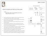
INSTALLATION ISSUES SPECIFIC TO WEATHER COVER APPLICATIONS
• Installation must comply with all governing codes.
• The bottom of the weather cover is open to ac com mo date piping and
electrical con nec tions.
• Electrical connections must be made with approved, outdoor-rated,
watertight conduit.
• Freeze protection must be provided on all water piping.
• Steam supply must be insulated.
• Avoid using steam hose in outdoor applications — the effects of ultraviolet
rays will prematurely age the steam hose.
• Installer required to drill a hole in weather cover for steam piping. Seal
after making steam connection to maintain weather protection.
• The steam outlet must be isolated with a union so the steam supply can be
dis con nect ed easily for removal of the weather cover to gain access to the
Vaporstream for service and maintenance.
ANNUAL WEATHER COVER MAINTENANCE REQUIREMENTS
• Check all fasteners and verify they are secure.
• Check for any sign of leakage — trace back to origin and repair.
mc_022510_1235
Installation notes
Open the hinged doors to make necessary
connections to the humidifi er. Refer to the
installation section of this manual for all
elec tri cal, supply water, and drain con nec tion
requirements.
Panel
Panel
Hinged door
OM-7435
Hinged
door
Panel
INSTALLATION
Table 13-1:
Weather cover weights
Weather cover size
Weight*
lbs kg
1-heater 390 177
3-heater 395 179
6-heater 430 195
9-heater 465 211
12-heater 500 227
* Weight does not include humidifi er or
control cabinet.
mc_030210_0950
The optional Vaporstream weather cover is
water-resistant and designed to protect the
humidifi er from rain and sun. The weather
cover has been tested and approved by ETL
Testing Laboratories, Inc., and is listed to UL
Standard 1995 and certifi ed to CAN/CSA
Standard C22.2 No. 236.
FIGURE 13-1: WEATHER COVER EXPLODED VIEW

14
VAPORSTREAM INSTALLATION, OPERATION, AND MAINTENANCE MANUAL
Weather cover
The Vaporstream Outdoor Enclosure is weather
tight with access doors and supplemental
heating and cooling. See Pages 14 through 21.
Table 14-1:
Weather cover dimensions
Letter Description
1-heater and
3-heater covers
6-heater cover 9-heater cover 12-heater cover
inches mm inches mm inches mm inches mm
A Height 66 1676 66 1676 66 1676 66 1676
B Length 44 1118 44 1118 44 1118 44 1118
C Width 35 889 39 991 44 1118 50 1270
D
Distance from
bottom
6 152 6 152 6 152 6 152
OM-7434
D
BC
A
INSTALLATION
Note:
Weather Covers are only available in the
United States and Canada.
FIGURE 14-1: WEATHER COVER DIMENSIONS

15
VAPORSTREAM INSTALLATION, OPERATION, AND MAINTENANCE MANUAL
Outdoor Enclosure:
INSTALLATION
Notes:
1. The Outdoor Enclosure has two available steam
dis tri bu tion confi gurations:
The standard con fi g u ra tion has a steam outlet
at the back of the Outdoor Enclosure for
con nect ing to steam dispersion unit piping.
The optional internal steam dis tri bu tion
con fi g u ra tion routes steam within the Outdoor
Enclosure and down through the enclosure pipe
chase into a building.
2. There are four knockouts located on the right
and left side of the enclosure. Knockout sizes
are 1½" (hole dia. 50 mm) for Vaporstream
models with 1-6 heaters and 2" (hole dia. 63.5
mm) for Vaporstream models with 9-12 heaters.
Run the electrical power into the en clo sure at
these knockouts.
3. All piping from the Vaporstream unit to the
steam outlet is stainless steel pipe. Depending
on the application, interconnecting piping from
the steam outlet to the dispersion assembly can
be tubing or DriSteem steam hose. See the
Dispersion section of this document for more
information about connecting to the dispersion
assembly.
4. A separate 20 amp, 120 Vac service must be
brought to the Outdoor Enclosure to power the
enclosure heaters and fans.
DC-1481
Optional
steam
outlet
Ventilation fan
Knockouts, 4"
(102 mm) on center
Enclosure drain 1½"
pipe thread (DN40)
with male nipple
Pipe chase
G
A
Vaporstream humidifi er
Standard
steam
outlet
See Note 2
Ventilation fan
K
4.5"
L
mc_030410_1500
FIGURE 15-1: VAPORSTREAM OUTDOOR ENCLOSURE WITH STANDARD OR OPTIONAL STEAM OUTLET, ELEVATION VIEW
Overview

16
VAPORSTREAM INSTALLATION, OPERATION, AND MAINTENANCE MANUAL
Outdoor Enclosure:
INSTALLATION
B
Standard steam outlet (exits enclosure
here)
Intake ven ti la tion fan
D
Front access door
C
Pipe chase extending
1" (25 mm) above fl oor
Vaporstream hu mid i fi er
Side access door
Side section heater
Enclosure drain
DC-1482
F
E
H
Optional steam outlet
(exits enclosure through pipe chase)
Front access door:
• Vaporstream models with
1-6 heaters have one acces
door
• Vaporstream models with
9-12 heaters have two
access doors
Front section optional heater
J
Control cabinet
Note: Some 9-12 heater
models have control cabinet
mounted on humidifi er
mc_030410_1505
Table 16-1:
Vaporstream Outdoor Enclosure dimensions*
Item Description
Vaporstream models
with 1-6 heaters with 9-12 heaters
inches mm inches mm
A Enclosure height 56.00 1422 56.00 1422
B Enclosure width 40.00 1016 54.00 1372
C
Pipe chase position
2.50 67 2.50 67
D 2.50 64 2.50 64
E
Pipe chase size
8.00 203 8.00 203
F 19.50 495 19.50 495
G
Steam hose and
tube position
13.50 343 13.50 343
H 22.00 559 29.50 899
J 7.00 178 7.00 178
K 8.25 210 9.25 235
L Length 60.00 1524 64.00 1626
* See drawings above and on facing page.
mc_030410_1520
FIGURE 16-1: VAPORSTREAM OUTDOOR ENCLOSURE, TOP VIEW
Overview
/