14
VAPORMIST INSTALLATION, OPERATION, AND MAINTENANCE MANUAL
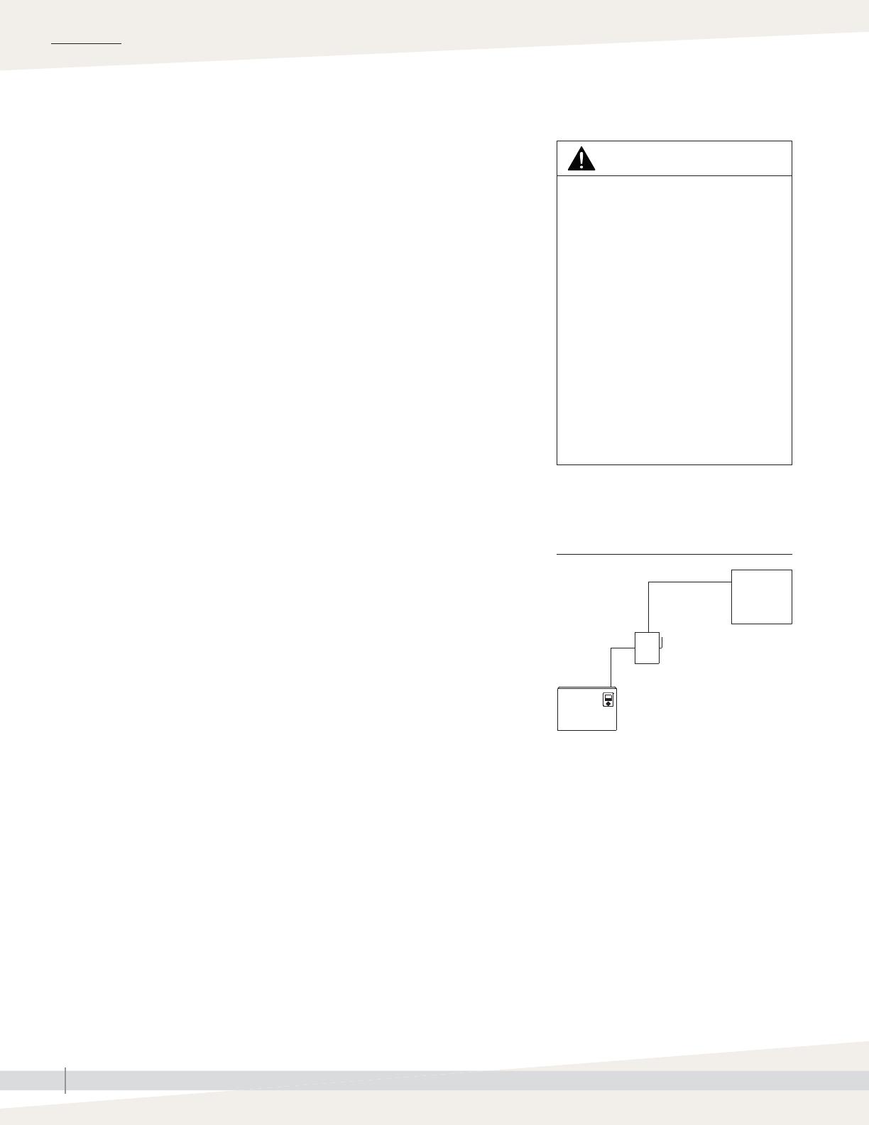
Fused
disconnect
(provided by
installer)
Power
supply
(provided
by installer)
OM-1007
Notes:
• Control wiring and power wiring must be
run in dedicated or separate earthed metal
conduit, cable trays, or trunking.
• Separate the line voltage wiring from low
voltage control circuit wiring when routing
electrical wiring inside the humidifier
cabinet.
• Do not use chassis or safety grounds as
current-carrying commons. Never use a
safety ground as a conductor or neutral to
return circuit current.
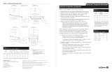
INSTALLATION
HUMIDIFIER FIELD WIRING
All wiring must be in accordance with all governing codes, and with the
humidifier wiring diagrams. The diagrams are located inside the removable
subpanel cover on the right side of the humidifier cabinet. Power supply wiring
must be rated for 220 °F (105 °C).
When selecting a location for installing the humidifier, avoid areas close to
sources of electromagnetic emissions such as power distribution transformers.
The fill valve, drain valve, probes, and temperature sensors use Class 2, 24
VAC power.
The use of semiconductor fusing sized per the National Electric Code is
recommended with the SSR option.
GROUNDING REQUIREMENTS
The approved earth ground must be made with solid metal-to-metal connections
and must be a good conductor of radio frequency interference (RFI) to earth
(multistranded conductors).
Ground wire should be the same AWG (mm2) size as the power wiring or
sized per NEC requirements (in Europe, IEC 60364 requirements).
PROPER WIRING TO PREVENT ELECTRICAL NOISE
Electrical noise can produce undesirable effects on electronic control circuits,
which affects controllability. Electrical noise is generated by electrical
equipment such as inductive loads, electric motors, solenoid coils, welding
machinery, or fluorescent light circuits. The electrical noise or interference
generated from these sources (and the effect on controllers) is difficult to define,
but the most common symptoms are erratic control or intermittent operational
problems.
Important:
• For maximum EMC (electromagnetic compatibility) effectiveness, wire all
humidity, high limit, and airflow controls using multicolored shielded/
screened plenum-rated cable with a drain wire for the shield/screen.
Connect the drain wire to the shield/screen ground terminal with wire less
than 2" (50 mm) in length.
• Do not ground shield at the device end.
mc_061610_0625-NA
Wiring
WARNING
Electric shock hazard
Only qualified electrical personnel
should perform field wiring installation
procedures. Improper wiring or contact
with energized circuits can cause
property damage, severe personal
injury, or death as a result of electric
shock and/or fire.
Do not remove the humidifier electrical
panel cover or the heater terminal cover
until electrical power is disconnected.
Contact with energized circuits can
cause property damage, severe
personal injury, or death as a result of
electrical shock.
mc_062310_0629
mc_062310_0630-VMHT
Vapormist
humidifier
FIGURE 14-1: FIELD WIRING
REQUIREMENTS