Page is loading ...

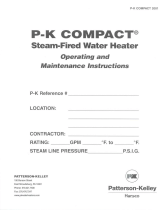
Ultra-sorb
®
Steam Dispersion Tube
Humidifier Panel
Installation, Operation,
and Maintenance Manual
For applications using steam from
a boiler or from any DRI-STEEM
steam generating humidifier.
US-IOM-0108.pdf 1 4/21/2010 11:34:49 AM

Page 2 • DRI-STEEM Ultra-sorb Steam Dispersion Panel Installation, Operation, and Maintenance Manual
Table of contents
Overview
Unpacking High-eciency tubes ...........................3
Field assembly of Model LH ...............................4
Field assembly of Model LV ...............................7
Installation
Selecting the location ......................................10
Determine humidier placement ............................11
Installation in a cold air stream .............................12
Mounting in a horizontal duct ..............................13
Mounting in a vertical duct ................................14
Installation inside an air handling unit .......................15
Supply and drain connections and dimensions ................16
Piping ...................................................17
Mounting ...............................................19
Retrofitting an existing Ultra-sorb ..........................20
Performance data .........................................22
Maintenance
Maintenance .............................................23
Troubleshooting guide .....................................24
Replacement parts ........................................26
Warranty .........................................Back cover
US-IOM-0108.pdf 2 4/21/2010 11:34:56 AM

DRI-STEEM Ultra-sorb Steam Dispersion Panel Installation, Operation, and Maintenance Manual • Page 3
Unpacking High-efficiency tubes
CAUTION!
The High-efficiency tubes are sleeved in clear poly
film for protection during processing, shipping,
and installation.
To prevent dirty insulating material, leave the clear
poly film on until installation is complete.
Equally important, remove and discard the clear
poly film before start-up by tearing it along the
perforations.
NOTE: If you have an Ultra-sorb without High-efficiency
dispersion tubes (non-insulated tubes), please skip to the next
page.
Unpacking
• Remove the dispersion assembly from the shipping container; be
careful not to bump or scrape the PVDF insulating material on
the dispersion tubes.
• Some dispersion panels are shipped unassembled by customer
request or by shipping necessity. Do not lay High-efficiency tubes
across or under anything that could compress or damage the
insulating material. Compressed insulating material has a reduced
R-value.
• Avoid bumping or snagging the PVDF insulating material.
Although PVDF is robust, rough handling can cause tears, which
could negatively impact performance.
•
Before start-up, remove the clear poly film by tearing it along the
perforation.
Do not use a knife or sharp object to remove the poly
film.
High-efficiency Tube option
Ultra-sorb dispersion assemblies with the
High-efficiency Tube option are designed to
produce significantly less dispersion-generated
condensate and airstream heat gain, which
reduces wasted energy by up to 85%. These
improvements are accomplished by reducing
the thermal conductivity of the tubes with
1/8" of polyvinylidene fluoride (PVDF)
insulating material on the outside of the tubes.
These assemblies require careful unpacking,
installation, and handling. If your dispersion
assembly has the High-efficiency Tube option,
be sure to read this section carefully.
Figure 3-1:
Ultra-sorb with the High-efficiency
Tube option
US-IOM-0108.pdf 3 4/21/2010 11:34:56 AM

Page 4 • DRI-STEEM Ultra-sorb Steam Dispersion Panel Installation, Operation, and Maintenance Manual
Field assembly of Model LH
Please read instructions while assembling
STEP 1 - Unpack
Unpack the Ultra-sorb components and verify that you have all
items on the packing list.
Note that both the supply header assembly and the condensate
header assembly have a ¾" half coupling drain connection on one
end. This will be the lower end of the installed dispersion assembly.
The supply header assembly has a steam inlet (nipple or tubing) on
the end opposite the drain connection.
Arrange the components on a large, flat working surface,
positioning them as indicated in Figure 4-1 (condensate header to
the left, supply header to the right).
OM-238-1
Mounting flange
Dispersion tube
¾" pipe thread coupling
(DN 20) drain connection
Slip coupling without shoulder
¼" - 20 nut (8)
¾" pipe thread coupling
(DN 20) drain connection
Washer (8)
¼" - 20 nut (8)
Slip coupling
with shoulder
Steam inlet
Supply header assembly
Mounting flange
Condensate header assembly
Tubelet
Figure 4-1:
Ultra-sorb Model LH
Table 4-1:
Ultra-sorb Model LH components
Description Qty.
Supply header assembly with shouldered
slip couplings
1
Condensate header assembly 1
Mounting flange 2
Dispersion tubes with slip couplings varies
¼ - 20 x ¾" bolt 8
¼ - 20 nut 8
¼ lock washer 8
US-IOM-0108.pdf 4 4/21/2010 11:34:57 AM

DRI-STEEM Ultra-sorb Steam Dispersion Panel Installation, Operation, and Maintenance Manual • Page 5
Field assembly of Model LH
OM-238-3
STEP 2 - Bolt the mounting flanges to the supply header
assembly
Refer to Figure 5-1 and 5-2.
Attach the two mounting flanges to the supply header assembly as
indicated using ¼" - 20 bolts with the nuts finger tight.
STEP 3 - Insert the dispersion tubes
Refer to Figure 5-3. Insert the plain ends (no slip couplings)
of the dispersion tubes into the slip couplings already mounted
on the supply header assembly. The slip couplings are factory
lubricated; if well aligned during insertion, no further lubrication
should be needed. Push and twist the tube in until it bottoms out
on the internal shoulder of the slip coupling (see Figure 5-4).
CAUTION! Use care to avoid cutting the internal O-rings of the
slip couplings.
Dispersion tube
Supply header
assembly
Slip coupling with shoulder
OM-238-6
Shoulder
O-rings
OM-239
¼" - 20 bolts
Mounting flange
OM-238-7
O-rings
Figure 5-1:
Supply header assembly
Figure 5-2:
Detail view of mounting flange
Figure 5-3:
Dispersion tubes
Figure 5-4:
Slip coupling with shoulder
Figure 5-5:
Slip coupling without shoulder
OM-238-2
Drain connection
Washer and nut
Steam inlet
Supply header assembly
¼" - 20 bolt
Washer and nut
¼" - 20 bolt
Mounting flange
Steam
inlet
US-IOM-0108.pdf 5 4/21/2010 11:34:57 AM

Page 6 • DRI-STEEM Ultra-sorb Steam Dispersion Panel Installation, Operation, and Maintenance Manual
OM-238-5
STEP 4 - Bolt the mounting flanges to the condensate header
assembly
Refer to Figure 6-1. Push the slip couplings onto the dispersion
tubes flush with the tube ends. Make sure the drain connection is
properly oriented. Attach the mounting flanges using
¼" - 20 bolts,
and leave the nuts finger tight.
STEP 5 - Slide the slip couplings onto the condensate header as-
sembly and orient the tubelets
SUGGESTION: Gripping the drain connection with vise grip pliers
and applying a back and forth rolling motion to the header will
assist in sliding the slip couplings into place.
Refer to Figure 6-2. It may be necessary to push and twist the
slip couplings onto the condensate header. Again care must be
taken to avoid cutting the internal O-rings. Slide the slip couplings
on until they bottom out against the stop disc on the condensate
header. The steam tubelets must be aimed so that they discharge the
steam perpendicular to the airstream. Rotate the dispersion tubes as
needed.
After tightening the ¼" - 20 bolts at all 4 corners, the Ultra-sorb
panel is ready for installation. See page 10.
Stop disc
Steam
inlet
Tubelet
Dispersion tube
Nut and washer (8)
¼" - 20 bolt (8)
Field assembly of Model LH
OM-238-4
Align coupling (without shoulder)
flush with end of dispersion tube
Mounting flange
¼" - 20 bolt
Dispersion tube
Mounting flange
Drain connection
Washer
and nut
Figure 6-1:
Condensate header assembly
Figure 6-2:
Slip coupling placement
Steam
inlet
Condensate header assembly
Supply header assembly
Condensate header assembly
Supply header assembly
US-IOM-0108.pdf 6 4/21/2010 11:34:57 AM

DRI-STEEM Ultra-sorb Steam Dispersion Panel Installation, Operation, and Maintenance Manual • Page 7
Figure 7-1:
Ultra-sorb Model LV
Field assembly of Model LV
Please read instructions while assembling
STEP 1 - Unpack
Unpack the Ultra-sorb components and verify that you have all
items on the packing list.
Lay the components on a flat surface, and position the header
assemblies as shown in Figure 7-1. Orient the condensate header
assembly so the ¾" half coupling drain connection is to your left,
and orient the supply header assembly so the steam inlet (nipple or
tubing) is to your right.
OM-260-1
Slip coupling
with shoulder
Supply header
assembly
Steam inlet
Tubelet
Dispersion tube
Mounting flange
¼" - 20 bolt (8)
A
A
Washer (8)
¼" - 20 nut (8)
Slip coupling without shoulder
Condensate header
assembly
¾" pipe thread coupling
(DN 20) drain connection
Mounting flange
Condensate drain
Table 7-1:
Ultra-sorb Model LV components
Description Qty.
Supply header assembly with shouldered
slip couplings
1
Condensate header assembly 1
Mounting flange 2
Dispersion tubes with slip couplings varies
Condensate drain tube 1
¼ - 20 x ¾" bolt 8
¼ - 20 nut 8
¼ lock washer 8
US-IOM-0108.pdf 7 4/21/2010 11:34:58 AM

Page 8 • DRI-STEEM Ultra-sorb Steam Dispersion Panel Installation, Operation, and Maintenance Manual
Field assembly of Model LV
STEP 2 - Bolt the mounting flanges to the supply header
assembly
Refer to Figure 8-1 and 8-2. Attach the two mounting flanges
as indicated using ¼" - 20 bolts with the nuts only finger tightened.
STEP 3 - Insert the dispersion tubes
Refer to Figure 8-4. Insert the plain ends (no slip couplings) of
the dispersion tubes into the slip coupling already mounted on the
supply header assembly. The slip couplings are factory lubricated;
if well aligned during insertion, no further lubrication should be
needed. Push and twist the tube in until it bottoms out on the inter
-
nal shoulder of the slip coupling. See Figure 8-3.
CAUTION! Use care to avoid cutting the internal O-rings of the
slip couplings.
OM-260-2
OM-260-3
¼" - 20 bolt
Washer and nut
Mounting
flange
Steam
inlet
Steam
inlet
Slip coupling
with shoulder
Dispersion
tube
Condensate
drain tube
OM-238-6
Shoulder
O-rings
OM-239
¼" - 20 bolts
Mounting flange
Figure 8-1:
Supply header assembly
Figure 8-2:
Detail view of mounting flange
Figure 8-4:
Dispersion tubes
Figure 8-3:
Detail view of slip coupling
Supply header assembly
Supply header assembly
US-IOM-0108.pdf 8 4/21/2010 11:34:58 AM

DRI-STEEM Ultra-sorb Steam Dispersion Panel Installation, Operation, and Maintenance Manual • Page 9
STEP 4 - Bolt the mounting flanges to the condensate header
assembly
Refer to Figure 9-1. Push the slip couplings onto the dispersion
tubes flush with the tube ends. Make sure the drain connection is
properly oriented. Attach the mounting flanges using
¼" - 20 bolts,
and leave the nuts finger tight.
STEP 5 - Slide the slip couplings onto the condensate header as-
sembly and orient the tubelets
SUGGESTION: Gripping the drain connection with vise grip pliers
and applying a back and forth rolling motion to the header will
assist in sliding the slip couplings into place.
Refer to Figure 9-2. It may be necessary to push and twist the
slip couplings onto the condensate header. Again care must be
taken to avoid cutting the internal O-rings. Slide the slip couplings
on until they bottom out against the stop disc on the condensate
header. The tubelets must be aimed so that they discharge the
steam perpendicular to the airstream. Rotate the dispersion tubes as
needed.
After tightening the ¼" - 20 bolts at all 4 corners the Ultra-sorb
panel is ready for installation. See page 10.
OM-260-4 OM-260-5
Steam
inlet
Tubelet
Dispersion
tube
¼" - 20 bolt (8)
Washer
and nut
Stop disc
Drain connection
Steam inlet
Mounting flange
Dispersion tube
¼" - 20 bolt
Washer and nut
Drain connection
Mounting flange
Condensate drain
Slip coupling
(without shoulder)
flush with end
of dispersion tube
Field assembly of Model LV
Figure 9-1:
Condensate header assembly
Figure 9-2:
Condensate header assembly
Supply header assembly
Supply header assembly
Condensate header assembly Condensate header assembly
US-IOM-0108.pdf 9 4/21/2010 11:34:58 AM

Page 10 • DRI-STEEM Ultra-sorb Steam Dispersion Panel Installation, Operation, and Maintenance Manual
Selecting the location
Ultra-sorb steam dispersion panels need a steam supply and a
method for trapping and removing condensate. See supply and
drain connections information on Page 16.
When selecting the location, first consideration should be given to
rapid, thorough absorption of the steam. The warmest air will most
readily absorb the steam.
The distance that unabsorbed steam will travel within a given
airstream has been cataloged by DRI-STEEM. See Figure 22-2.
A. You must install the
Ultra-sorb panel in a location where the
water vapor being discharged will be absorbed by the airstream.
B. In general, place the Ultra-sorb panel where the air temperature
is capable of absorbing steam being discharged without
causing condensation at or after the unit. This will normally be
downstream of the heating coil or where the air temperature is
warmest.
C. Do not place the Ultra-sorb panel in an outside air intake unless
the air is tempered with a preheat coil.
D. Do not place the Ultra-sorb panel too near to the entrance of a
high-efficiency filter. The filter will remove the visible moisture
and become waterlogged. See Note 3 on page 22 for absorption
(non-wetting) distance.
E. Do not place the Ultra-sorb panel where discharged visible mist
will impinge directly on a metal surface.
Note: To prevent leakage, use HVAC caulking or a similar weather
sealant to seal all places where the Ultra-sorb installation hardware
and ttings penetrate the wall of the duct.
Installation
US-IOM-0108.pdf 10 4/21/2010 11:34:58 AM

DRI-STEEM Ultra-sorb Steam Dispersion Panel Installation, Operation, and Maintenance Manual • Page 11
Installation
Outside air
Relief air
Preheat coil
Motorized
air dampers
Supply airflow
Filters
Economizer
control device
Heating coil
Cooling coil
8' to 12' (2.4 to 3.7 m)
Duct high limit humidity control for dispersion
locations A, B
Airflow proving switch
Airflow proving switch
Duct high limit humidity control
for dispersion location C
Return airflow
8' to 12'
(2.4 to 3.7 m)
3' to 5'
(1 to 1.5 m)
Fan
Figure 11-1:
Placing a dispersion assembly in an AHU
ABD
C
Exterior
building wall
mc_092507_1530
Determine humidifier placement
Check available non-wetting distance, and review the
recommendations in Figure 11-1. Dispersed steam must
be absorbed into the airflow before it comes in contact with
duct elbows, fans, vanes, filters, or any object that can cause
condensation and dripping.
Placement in an air handling unit
• Location A is the best choice.
Installing downstream of heating
and cooling coils provides laminar flow through the dispersion
unit; plus, the heated air provides an environment for best
absorption.
• Location B is the second-best choice. However, in change-
over periods, the cooling coil will eliminate some moisture for
humidification.
• Location C is the third-best choice. Air leaving a fan is usually
very turbulent and can cause vapor to not absorb at the expected
absorption distance. Allow for more absorption distance if
installing downstream of a fan.
• Location D is the poorest choice. The cooler air at this location
requires an increased absorption distance.
US-IOM-0108.pdf 11 4/21/2010 11:34:58 AM

Page 12 • DRI-STEEM Ultra-sorb Steam Dispersion Panel Installation, Operation, and Maintenance Manual
Installation
Elbow
Duct
Air flow
Air flow
Ultra-sorb
Ultra-sorb
Duct split
Ultra-sorb
Air flow
Drip pan
Pipe to drain size as required
Ceiling line
Vapor absorption
area
* This length of duct should have sealed seams and
should be at least three times the height of the
Ultra-sorb panel.
Ceiling line
Ultra-sorb
A'
Air flow
Blower
Installation in a cold air stream
When a humidifier is installed in a duct that will carry cold air
periodically, determine the dew point temperature.
If the psychrometric chart reveals that saturation may occur, protec-
tion should be provided. A high limit humidistat or thermostat set to
cut off the humidifier at a safe temperature can be used for this purpose.
Placement upstream of an elbow or duct split
Due to the rapid steam absorption performance of the Ultra-sorb
panels, installation upstream from elbows or duct splits can be done
with confidence. However, all mechanical equipment is subject to
accidental failure. Therefore, if the installation is above expensive
or irreplaceable objects, a galvanized drip pan should be installed to
prevent accidental spillage. See Figure 12-3.
Installation above valuable equipment
Water piping and humidifiers should not be installed above
expensive equipment. A leaking water pipe, condensation, or
other accidental water spillage could cause serious damage to the
equipment below.
When such an installation cannot be avoided, install a galvanized
drip pan under the humidifier, valve, etc. to catch and drain away
the spill.
The condensate from the Ultra-sorb panel should be piped as
shown on Page 16 and should not be discharged into the pan.
Recirculation unit
In an application where no duct system exists, or if the duct air is
too cool for proper humidity absorption, a recirculation fan can be
used. The fan circulates room temperature air across the humidifier
and discharges humidified air into the space. Select the air discharge
point carefully to avoid condensation on surfaces of the building or
equipment. See Figure 12-4.
OM-178
Figure 12-2:
Upstream placement
Non-wetting
distance from
Figure 22-2
OM-198
Figure 12-3:
Installation above valuable equipment
2" (50 mm)
Figure 12-4:
Recirculation unit
OM-197
Cold
air flow
Ultra-sorb
Extended trails of
fog may develop
High limit duct humidistat
to be mounted 10-15 feet
downstream of Ultra-sorb
Figure 12-1:
Installation in cold air stream
US-IOM-0108.pdf 12 4/21/2010 11:34:58 AM

DRI-STEEM Ultra-sorb Steam Dispersion Panel Installation, Operation, and Maintenance Manual • Page 13
Installation
Mounting in a horizontal duct
The Ultra-sorb panel is contained within a mounting frame.
A mounting flange 1½" (38 mm) wide is provided on all four sides
of the unit. The 1½" (38 mm) wide portion of the header enclosure
is intended to be a mounting flange. See Figures 13-1 and 13-2. A
matching flange or metal frame is required on the ductwork for
connection to the Ultra-sorb flanges. The recommended fastener is
a #12 x ¾" self-drilling and tapping screw, spacing not to exceed 12"
(305 mm). If an angle-iron frame is provided on the duct section,
a longer screw may be required.
Note: To avoid puncturing the
header, screw penetration into the header enclosure should not
exceed ¾" (20 mm).
Header support gasket secures header
within enclosure
Header enclosure
1½" (38 mm) Mounting flange
1½" (38 mm) Mounting flange
Mounting flanges of duct are attached
to header enclosure
Ultra-sorb
Header enclosure
Mating flanges of duct are
attached to header enclosures
Header enclosure
1½" (38 mm) Mounting flange
Mating flanges of duct are
attached to header enclosures
OM-203
Figure 13-3:
Plan view - Model LH
OM-234
Figure 13-2:
Elevation
Figure 13-1:
Elevation view - Model LH
OM-177
US-IOM-0108.pdf 13 4/21/2010 11:34:58 AM

Page 14 • DRI-STEEM Ultra-sorb Steam Dispersion Panel Installation, Operation, and Maintenance Manual
Installation
Mounting in a vertical duct
Vertical airflow Ultra-sorb panels must be ordered for this
application. Headers and tubes are pitched to accommodate vertical
mounting. The Ultra-sorb panel is contained within a mounting
frame. A mounting flange 1½" (38 mm) wide is provided on all
four sides of the unit. The 1½" (38 mm) wide portion of the header
enclosure is intended to be a mounting flange. See Figure 14-3. A
matching flange or metal frame is required on the ductwork for
connection to the Ultra-sorb flanges. The recommended fastener is
a #12 x ¾" self-drilling and tapping screw, spacing not to exceed 12"
(305 mm). If an angle-iron frame is provided on the duct section,
a longer screw may be required. Note: To avoid puncturing the
header, screw penetration into the header enclosure should not
exceed ¾" (20 mm).
Air flow
Condensate
drain in
dispersion
tubes
Air flow
Condensate
drain in
header
Steam inlet
Header
enclosure
Header
enclosure
1½" (38 mm) mounting flange
Mating flanges of duct are attached
to header enclosures
Header enclosure gasket secures header within enclosure
1½" (38 mm) mounting flange
Mating flanges of duct are attached
to header enclosures
OM-203-A
Figure 14-3:
Plan view - Model VAF
OM-234-A
Figure 14-1:
Elevation view - Model VAF
(for vertical airflow)
OM-466
Figure 14-2:
Side view - Model VAF
US-IOM-0108.pdf 14 4/21/2010 11:34:58 AM

DRI-STEEM Ultra-sorb Steam Dispersion Panel Installation, Operation, and Maintenance Manual • Page 15
Installation
Installation inside an air handling unit
See placement recommendation in Figure 11-1.
The metal support frame should be anchored to the air handler
casing. Recommended fasteners for mounting the Ultra-sorb to a
metal support frame are ¼ - 20 nuts and bolts or #12 self drilling
and tapping screws. Due to the possible forces exerted on this
application, DRI-STEEM recommends fastener spacing not to
exceed 6" (150 mm). On larger Ultra-sorb installations, vertical
channels may be required on both the inlet and outlet ends of the
humidifier to provide proper support. See Figure 15-2.
Air flow
Mounting channel (Typ)
Blank-off plate
Side blank-off
Steam supply header
Additional mounting support channels
required on larger Ultra-sorb units
Air handler casing
Supply header
Ultra-sorb
overall width
Steam
supply
AHU casing
AHU coil
Mounting
channel (Typ)
Floor drain
Condensate header
Blanked-off area
1" (25 mm) air gap
DC-1439
Figure 15-1:
Ultra-sorb installed inside an air handler
OM-199
Figure 15-2:
Vertical channels
Air
handler
overall
height
Air handler overall width
Ultra-sorb
overall
height
See Page 16 for trap dimensions.
US-IOM-0108.pdf 15 4/21/2010 11:34:58 AM

Page 16 • DRI-STEEM Ultra-sorb Steam Dispersion Panel Installation, Operation, and Maintenance Manual
Supply and drain connections
and dimensions
mc_082107_1139
Figure 16-1:
Connection to a boiler (pressurized steam applications)
Steam
supply
Steam control valve
Strainer
Steam trap
Ultra-sorb unit
OM-687C
Figure 16-2:
P-trap water seal dimensions
Note:
For detailed information about steam piping, see the DRI-STEEM Humidification System Design
Guide, which can be downloaded from the literature section of our web site: www.dristeem.com
Table 16-1:
Condensate drain piping for Ultra-sorb steam dispersion panels
Evaporative steam Pressurized steam
Standard Clean-steem Standard Clean-steem
P-trap water seal
(See Figure 16-2)
Drop: 6"
Seal: 5"
Stainless steel
Drop: 6"
Seal: 5"
Recommended
method
Drop: 8"
Seal: 10"
Stainless steel
Drop: 8"
Seal: 10"
F&T trap
(See Figure 16-3)
No No
Alternate
method *
Drop: 12"
Drip: 4"
No
Inverted bucket
trap
No No No No
Stainless steel
thermostatic trap
No No No No
Condensate to
open drain
Yes Yes Yes Yes
Condensate return
by condensate
pump
Yes
Yes
stainless
steel pump
recommended
Yes
Yes
stainless
steel pump
recommended
Condensate return
to humidifier by
gravity
Yes Yes NA NA
Condensate return
to boiler via return
line
NA NA No No
* Provide 18" vertical clearance for future P-trap substitution if required.
Drop
Seal
Figure 16-3:
F&T trap dimensions
Drop
Drip
Clearance
Figure 16-4:
Lifting condensate
To condensate
return main
From P-trap or
mechanical trap
Condensate
pump
Check valve
1” (25 mm) air gap
1” (25 mm) air gap
F&T trap
Note:
The Ultra-sorb must be installed with the drain
connection at an elevation that permits gravity drainage.
For lifting condensate, use a condensate pump rated for
your application. Pumps are rated by fluid temperature,
head (pressure), and flow (gpm). Contact your local
DRI-STEEM representative for pump selection.
Ultra-sorb
condensate outlet
3/4” (20 mm) minimum
copper
Ultra-sorb
condensate outlet
US-IOM-0108.pdf 16 4/21/2010 11:34:58 AM

DRI-STEEM Ultra-sorb Steam Dispersion Panel Installation, Operation, and Maintenance Manual • Page 17
Steam from a boiler
Ultra-sorb panels for boiler steam have a threaded pipe nipple that
extends outside the framework for a steam supply connection. The
steam supply line should be dripped immediately ahead of the
steam valve through a steam trap.
Recommended drip trap type: (See Page 16 for trap dimensions)
Low pressure: Less than 15 psi — Float and Thermostatic (F&T)
High pressure: More than 15 psi — Inverted Bucket
Install wye strainer ahead of the steam valve.
Two ¾" (20 mm) F&T traps, one for each header, are required on
the horizontal dispersion tube (Model LH) Ultra-sorb. One float
and thermostatic trap is required on the lower header of the vertical
tube (Model LV) Ultra-sorb.
1. To ensure driest steam, take the humidifier steam supply off the
top of the steam main (instead of side or bottom).
2. An air flow proving switch is recommended to prevent the steam
valve from opening if air is not moving in the duct.
3. To prevent over saturation when duct air is cooler than 70 °F
(21 °C), high limit (duct mounted) humidistat at least 15 feet
(4.5 m) downstream and set at 80-90% is recommended.
4. Steam from the dispersion tube tubelets must be discharged at
right angles to the airstream for best non-wetting results.
Piping
Figure 17-1:
Ultra-sorb strainer
Install strainer same size as
valve and within 3" (1 m)
of Ultra-sorb
Valve
Table 17-2:
O.D. of pipe and tubing
Nom.
Dia.
Standard
pipe
Tubing
copper
Tubing
SST
I.D. of
hose
1¼"
(30 mm)
1.660 1.375 - -
1½"
(38 mm)
1.900 1.625 1.500 1.50
2"
(50 mm)
2.375 2.125 2.000 2.00
2½"
(65 mm)
2.875 2.625 3.000 3.00
Note: Pipe thread and flange tubing adapters
are available from DRI-STEEM.
From
steam
source
Table 17-1:
Maximum steam carrying capacity and length of interconnecting vapor hose, tubing, and pipe*
Vapor hose
†††
Copper or stainless steel tubing
and Schedule 40 steel pipe
Hose I.D. Maximum capacity Maximum length** Tube or pipe size*** Maximum capacity
Maximum developed
length
†
inches DN lbs/hr kg/h ft m inches DN lbs/hr kg/h ft m
1½ 40 150 68 10 3 1½ 40 150 68 20 6
2 50 250 113 10 3 2 50 220 100 30 9
3
††
80
††
450 204 80 24
4
††
100
††
750 340 100 30
5
††
125
††
1400 635 100 30
6
††
150
††
2300 1043 100 30
* Based on total maximum pressure drop in hose, tubing, or piping of 5" wc (1244 Pa)
** Maximum recommended length for vapor hose is 10' (3 m). Longer distances can cause kinking or low spots.
*** To minimize loss of capacity and efficiency, insulate tubing and piping.
†
Developed length equals measured length plus 50% of measured length to account for pipe fittings.
††
Requires flange connection
†††
When using vapor hose, use DRI-STEEM vapor hose for best results. Field-supplied hose may have shorter life and may cause foaming in the evaporating
chamber resulting in condensate discharge at the dispersion assembly. Do not use vapor hose for outdoor applications.
US-IOM-0108.pdf 17 4/21/2010 11:34:58 AM

Page 18 • DRI-STEEM Ultra-sorb Steam Dispersion Panel Installation, Operation, and Maintenance Manual
Steam from an evaporative humidifier
Hard pipe or tubing
Standard steam hose connections on DRI-STEEM evaporative
humidifiers are 1½" (38 mm) stainless steel tubing. Two inch
tubing connections are available as an option on higher capacity
evaporative units. Hose cuffs are available for connecting hard pipe
to the tubing connection on the vaporizing humidifier and to the
Ultra-sorb (see Figure 18-2). If specified, DRI-STEEM can also
provide threaded connections on the vaporizing humidifier and on
the Ultra-sorb (see Figure 18-3).
When non-threaded pipe is used, connections at both ends are
completed with rubber vapor hose. Due to the difference in O.D. of
pipe and tubing compared to I.D. of hose, multiple hose clamps may
be required.
Vapor hose
• Support vapor hose to prevent sags or low spots, and pitch at least
2" (50 mm/m) per foot back to the humidifier.
Vapor rigid piping
• Pitch at least 2" (165 mm/m) per foot back to the humidifier.
• 90° elbows are not recommended. Use two 45° elbows one foot
apart (see Figures 18-2 and 18-3).
Failure to follow the above recommendations may result in excessive
back pressure on the vaporizing humidifier. This may lead to loss of
water seal or leaking gaskets. When the distance between the
Ultra-sorb and the vaporizing humidifier exceeds 20 feet (6 m),
consult the factory for special recommendations.
• Thin wall tubing will heat up with less start up heat loss than
heavy wall pipe.
• Insulating the tubing or piping will reduce the loss in output
caused by condensation in the tubing or piping.
Condensate Drainage
Since Ultra-sorb panels operate with virtually zero internal pressure,
condensate cannot be piped directly into a return main. It must be
wasted to a floor drain or piped into a small condensate pump and
returned to the steam source.
To prevent steam from escaping down the drain line, install a
water seal or steam trap in the drain line. The water seal must be of
sufficient height to contain the pressure in the humidifier.
See Page 16 for trap dimensions.
Piping
Vapor hose
(See Figure 22-2)
Ultra-sorb
Ultra-sorb
Additional connections
can be provided for
multiple evaporative
humidifier connections
Insulated hard pipe
or tubing (See Table 17-2)
Hose
cuff and
clamps
DRI-STEEM
evaporative
humidifier
Additional connections
can be provided for
multiple evaporative
humidifier connections
Ultra-sorb
45° elbows recommended
Insulated hard pipe or
tubing (See Table 17-2)
Pipe union
Optional threaded
outlet on cover
DRI-STEEM
evaporative
humidifier
Standard 1½" (38 mm)
tubing outlet on cover
OM-155
Figure 18-1:
Vapor hose
DRI-STEEM
evaporative
humidifiers
Figure 18-2:
Hose cuff installation
OM-180
Hose and
cuff clamps
45° elbows
recommended
Figure 18-3:
Threaded connections
OM-180
US-IOM-0108.pdf 18 4/21/2010 11:34:58 AM

DRI-STEEM Ultra-sorb Steam Dispersion Panel Installation, Operation, and Maintenance Manual • Page 19
The Ultra-sorb panel can operate with air flow in either direction;
however, the steam supply must be connected to the top of the
assembly, and condensate must be drained from the bottom of the
assembly.
The duct section and Ultra-sorb panel must be properly supported
to carry the weight of the assembly. The weight of the piping must
be supported by the building structure rather than by the Ultra-sorb
unit. Otherwise, the weight may impose stress on the connections,
causing them to fracture and leak. Before start up, verify that all
steam discharge tubelets are pointed perpendicular to the airstream
(see Figure 19-2). The slip couplings provide easy rotation of the
dispersion tubes for proper tubelet orientation.
When removing and installing slip couplings, verify that the
O-rings are seated in their grooves and lubricated. When sliding the
dispersion tube into the slip coupling, be careful not to cut the
O-rings.
Mounting
Air flow
Tubelet
Dispersion tube
Slip coupling
with O-rings
and shoulder
Steam
supply
Steam supply
Dispersion tube
Tubelet
Condensate drain
connection
Header
Header
Condensate drain
connection
OM-186
Figure 19-3:
Ultra-sorb Model LV
Figure 19-2:
Proper dispersion tube orientation
Figure 19-1:
Ultra-sorb Model LH
OM-204
OM-150a
Slip coupling without
O-rings and no shoulder
US-IOM-0108.pdf 19 4/21/2010 11:34:58 AM

Page 20 • DRI-STEEM Ultra-sorb Steam Dispersion Panel Installation, Operation, and Maintenance Manual
Removing uninsulated tubes
Note: The photos below depict Ultra-sorb Model LV (vertical
tubes). The supply header is on the top, and the condensate
header is on the bottom. If retrofitting an Ultra-sorb Model
LH (horizontal tubes), pay attention to the location of the
supply and condensate headers.
Perform the following steps for each uninsulated tube being
removed:
1. With a pulling and twisting
motion, slide the slip coupling
off the condensate header far
enough to reveal the end of the
dispersion tube.
2. Swing the dispersion tube away
from the condensate header;
pull the dispersion tube and
slip coupling off the supply
header.
Before retrofitting an existing Ultra-sorb panel with high-efficiency
tubes, shut off steam to the system, and let all hot surfaces cool. See
the Warning below.
Note: Replacement slip couplings with internal O-rings are shipped
with retrofit high-efficiency tube orders. There are two types
of slip couplings: with shoulders and without. Slip couplings
with shoulders must go on the supply header end of the
dispersion tube. See Figure 20-2.
Figure 20-2:
Dispersion tube slip couplings
OM-238-7
O-rings
OM-238-6
O-rings
Shoulder
Step 1
Step 2
Retrofitting an existing Ultra-sorb
WARNING!
Steam humidification systems have
extremely hot surfaces.
To avoid burns, allow humidifier, steam
pipes, and dispersion assembly to cool
before touching any part of the system.
Figure 20-1:
PVDF insulating material
The white PVDF
insulating material
stays on the tubes.
Do NOT remove it.
US-IOM-0108.pdf 20 4/21/2010 11:34:59 AM
/