Page is loading ...

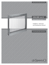
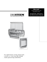
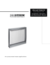
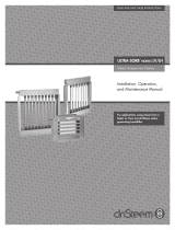
ULTRA-SORB
®
MODEL MP
Steam Dispersion Panels
Installation, Operation,
and Maintenance Manual
READ AND SAVE THESE INSTRUCTIONS
For applications using steam from a
boiler or from any DriSteem steam
generating humidifier.

ii
ULTRA-SORB MODEL MP INSTALLATION, OPERATION, AND MAINTENANCE MANUAL
ATTENTION INSTALLER
Read this manual before installing.
Leave manual with product owner.
DriSteem Technical Support
• 800-328-4447
• dristeem.com/technical-support
WARNING
Hot surface hazard
Steam humidifi cation systems have
extremely hot surfaces.
To avoid burns, allow humidifi er, steam
pipes, and dispersion assemblies to
cool before touching any part of the
system.
mc_071411_0753
UNPACKING HIGH-EFFICIENCY TUBES. . . . . . . . . . . . . . . . . . . . . . . . . . . . . . . . . . . . . . . . . . . . .1
INSTALLATION . . . . . . . . . . . . . . . . . . . . . . . . . . . . . . . . . . . . . . . . . . . . . . . . . . . . . . . . . . . . . .2
Ultra-sorb Model MP field assembly . . . . . . . . . . . . . . . . . . . . . . . . . . . . 2
Ultra-sorb Model MP mechanical specifications . . . . . . . . . . . . . . . . . . . . 4
Selecting the location . . . . . . . . . . . . . . . . . . . . . . . . . . . . . . . . . . . . . . 6
Determine humidifier placement . . . . . . . . . . . . . . . . . . . . . . . . . . . 6
Placement in an air handling unit . . . . . . . . . . . . . . . . . . . . . . . . . . 6
Mounting and support . . . . . . . . . . . . . . . . . . . . . . . . . . . . . . . . . . . . . 8
Installation in a cold air stream . . . . . . . . . . . . . . . . . . . . . . . . . . . 8
Placement upstream from an elbow or duct split . . . . . . . . . . . . . . . . 8
Installation above valuable equipment . . . . . . . . . . . . . . . . . . . . . . . 8
Panel support . . . . . . . . . . . . . . . . . . . . . . . . . . . . . . . . . . . . . . . . 8
Ultra-sorb Model MP mounting - pressurized steam application . . . . . . . . 10
Ultra-sorb Model MP mounting - nonpressurized steam application . . . . . 11
Mounting in an air handling unit . . . . . . . . . . . . . . . . . . . . . . . . . . 12
Mounting in a horizontal duct . . . . . . . . . . . . . . . . . . . . . . . . . . . . 13
Supply and drain connections and dimensions . . . . . . . . . . . . . . . . . . . 14
Ultra-sorb Model MP connections and dispersion tube detail . . . . . . . . . 15
Piping . . . . . . . . . . . . . . . . . . . . . . . . . . . . . . . . . . . . . . . . . . . . . . . 16
Steam from a Pressurized steam . . . . . . . . . . . . . . . . . . . . . . . . . . 17
Steam from a non-electrode-type evaporative humidifier . . . . . . . . . . 18
Steam from an electrode-type evaporative humidifier . . . . . . . . . . . . 19
OPERATION . . . . . . . . . . . . . . . . . . . . . . . . . . . . . . . . . . . . . . . . . . . . . . . . . . . . . . . . . . . . . . 20
Replacing Ultra-sorb Model MP dispersion tubes . . . . . . . . . . . . . . . . . . 20
Performance data . . . . . . . . . . . . . . . . . . . . . . . . . . . . . . . . . . . . . . . 21
Controls . . . . . . . . . . . . . . . . . . . . . . . . . . . . . . . . . . . . . . . . . . . . . . 22
Startup . . . . . . . . . . . . . . . . . . . . . . . . . . . . . . . . . . . . . . . . . . . . . . . 23
MAINTENANCE . . . . . . . . . . . . . . . . . . . . . . . . . . . . . . . . . . . . . . . . . . . . . . . . . . . . . . . . . . . 24
Inspecting and servicing components . . . . . . . . . . . . . . . . . . . . . . . . . . 24
Strainer . . . . . . . . . . . . . . . . . . . . . . . . . . . . . . . . . . . . . . . . . . . 24
Steam traps on main steam supply . . . . . . . . . . . . . . . . . . . . . . . . 24
Valves . . . . . . . . . . . . . . . . . . . . . . . . . . . . . . . . . . . . . . . . . . . . 24
High-Efficiency Tubes . . . . . . . . . . . . . . . . . . . . . . . . . . . . . . . . . . 24
Troubleshooting . . . . . . . . . . . . . . . . . . . . . . . . . . . . . . . . . . . . . . . . . 25
Replacement parts . . . . . . . . . . . . . . . . . . . . . . . . . . . . . . . . . . . . . . . 28
WARRANTY . . . . . . . . . . . . . . . . . . . . . . . . . . . . . . . . . . . . . . . . . . . . . . . . . . . . . . . . . . . . . . 32
Table of contents

1
ULTRA-SORB MODEL MP INSTALLATION, OPERATION, AND MAINTENANCE MANUAL
Unpacking High-Effi ciency Tubes
NOTE: If you have an Ultra-sorb without High-effi ciency dispersion tubes (non-
insulated tubes), please skip to the next page.
UNPACKING
• Remove the dispersion assembly from the shipping container; be careful not
to damage the PVDF insulating material on the dispersion tubes.
• Some dispersion panels are shipped unassembled. Do not lay High-
Effi ciency Tubes across or under anything that could compress or damage
the insulating material. Compressed insulating material has a reduced
R-value.
• Before start-up, remove the clear poly fi lm covering the insulation by tearing
it along the perforation. Do not use a knife or sharp object to remove the
poly fi lm.
High-efficiency tube option
Dispersion assemblies with the High-Effi ciency
Tube option are designed to produce
signifi cantly less dispersion-generated
condensate and airstream heat gain, which
reduces wasted energy by up to 85%.
CAUTION
Remove clear poly fi lm; do not remove white PVDF insulation.
High-effi ciency tubes are sleeved in clear poly fi lm for
protection during, shipping, and installation. Leave the clear
poly fi lm on until installation is complete.
Remove and discard the clear poly fi lm before start-up by
tearing it along the perforations. Do not remove the white
PVDF insulation.
• Keep fl ame away from the insulation to avoid damage.
• PVDF is resistant to UV light. UV-C light from
germicidal lamps will not cause the insulating
material to degrade.
• Do not tighten mounting clamps or fasteners to any part of the dispersion tube.
UNPACKING HIGH-EFFICIENCY TUBES

2
ULTRA-SORB MODEL MP INSTALLATION, OPERATION, AND MAINTENANCE MANUAL
Ultra-sorb Model MP fi eld assembly
INSTALLATION
Note: These assembly instructions are for Ultra-sorb Model MP panels shipped
unassembled by request or as required. Panels with overall height more
than 98" (2490 mm) are shipped unassembled.
LAY OUT THE PANEL COMPONENTS
Place the panel components on a large, fl at working surface.
ATTACH THE TOP FRAME ASSEMBLY
Span the fl anges with the top frame assembly. Align the locating pins on the
fl anges and top frame, and insert screws.
TIGHTEN THE FLANGE LOCKNUTS
Torque the eight fl ange locknuts to 16 ft-lb (22 N-m) at 100 rpm maximum
using a 7/16" deep-well socket.
INSTALL THE DISPERSION TUBES
Note: Do not remove the poly fi lm from the dispersion tubes until after the
panel is installed.
Table 2-1:
Ultra-sorb Model MP components
Component Qty.
Header assembly 1
Dispersion tubes Varies
Top frame assembly 1
Side fl anges 2
Screws Varies
Flange locknuts 8
Header
assembly
Flange
locknut
Left side
fl ange
OM-7846
Top frame
assembly
Right side fl ange
Insulation
FIGURE 2-1: ULTRA-SORB MODEL MP COMPONENTS
Dispersion
tube
Locating pins

3
ULTRA-SORB MODEL MP INSTALLATION, OPERATION, AND MAINTENANCE MANUAL
Ultra-sorb Model MP fi eld assembly
INSTALLATION
INSERT DISPERSION TUBES INTO AN UNASSEMBLED ULTRA-SORB PANEL
If the Ultra-sorb Model MP panel was shipped unassembled, the dispersion
tubes need to be inserted into the panel.
Note: Use soapy water to lubricate end of tubes where inserted into rubber
grommet.
1. Insert tube into rubber grommet at panel header, with open end at bottom.
Insert at a slight angle to not interfere with top frame of Ultra-sorb panel.
2. Press downward on tube so to clear stud at top of tube. Align tube with
rivet nut on top of the header.
3. Once aligned, turn the tube three full rotations into rivet nut for proper
engagement.
4. Turn the tube backwards so that the steam tubelets face the next tube,
perpendicular to air flow. Face the lowest tubelet of each tube in the same
direction so the facing tubelets are at staggered heights.
5. Tighten the locknut down to the top header to 10 in-lbs (1.13 N-m).
Note: If the rivet nut pulls through, add a ¼"-20 nut on each side of the
top flange to secure the tube.

4
ULTRA-SORB MODEL MP INSTALLATION, OPERATION, AND MAINTENANCE MANUAL
Ultra-sorb Model MP mechanical specifi cations
INSTALLATION
FIGURE 4-1: ULTRA-SORB MODEL MP DIMENSIONS
OM-7915_mp
Top view
Elevation view
Blank
side view
Header
Connections
side view
A
A’
B’
C
D
B
F
E
G
H
J
Table 4-2:
Ultra-sorb Model MP tube capacity*
Tubes lbs/hr kg/hr
1.5"
Uninsulated 40 18.1
Insulated 43 19.5
2.0"
Uninsulated 77 34.9
Insulated 80 36.3
* If face height (B') is <17" (432 mm), consult
DriSteem or see DriCalc for the correct calculation.
Table 4-1:
Ultra-sorb Model MP unit capacity
Evaporative steam Pressurized steam (2-50 psi)
lbs/hr kg/hr lbs/hr kg/hr
700 318 2720 1235
All except with
4" steam inlet
4" steam
inlet
G
H
Note:
See Table 5-1: Ultra-sorb MP dimensions

5
ULTRA-SORB MODEL MP INSTALLATION, OPERATION, AND MAINTENANCE MANUAL
INSTALLATION
Ultra-sorb Model MP mechanical specifi cations
Table 5-1:
Ultra-sorb Model MP dimensions
Dimension Inches (mm)
A Unit width 15" (380 mm) min, 147" (3735 mm) max, in ½" (13 mm) increments
A' Face width 12" (305 mm) min, 144" (3660 mm) max, in ½" (13 mm) increments
B Unit height* 19.375" (492 mm) min, 151.375" (3845 mm) max, in ½" (13 mm) increments
B' Face height 12" (305 mm) min, 144" (3660 mm) max, in ½" (13 mm) increments
C Frame depth
7.2" (183 mm)
2.3" (58 mm) for side drain port (H) when 4" coupling (DN100) steam inlet
D Frame enclosure 1.5" (38 mm)
E Header enclosure 5.85" (149 mm)
F Mounting fl ange 1.5" (38 mm)
G Humidifi cation
steam inlet
1" or 2" NPT coupling, for pressurized steam
1½" or 2" NPT coupling, for evaporative steam
3" or 4" flange, for evaporative steam
DN25 or DN50 BSPT nipple, for pressurized steam
DN50, DN80, or DN100 BSPT nipple, for evaporative steam
1½" or 2" (DN40 or DN50) hose, for evaporative steam
H Drain port
(internal thread)
¾" NPT (DN20) coupling
J Overall width
1" NPT coupling, dimension A + 1/8";
1½" NPT coupling, dimension A + ½";
2" NPT coupling, dimension A + 1"
3" and 4" flange connection, dimension A + 6.5"
DN25, DN50, DN80 BSP nipple, dimension A + 38 mm
DN100 BSP nipple, dimension A + 64 mm
1½" or 2" (DN40 or DN50) hose connection, dimension A + ½" (dimension A + 13 mm)
* Panels with unit height more than 120" (3048 mm) have two-piece side fl anges and are shipped with brackets for easy fi eld assembly. Panels
with unit height more than 98" (2490 mm) are shipped unassembled.

6
ULTRA-SORB MODEL MP INSTALLATION, OPERATION, AND MAINTENANCE MANUAL
Selecting the location
INSTALLATION
PLACEMENT IN AN AIR HANDLING UNIT
• Location A is the best choice. Installing downstream from heating and
cooling coils provides laminar fl ow through the dispersion unit; plus, the
heated air provides an environment for best absorption.
• Location B is the second-best choice. However, conditions when both
cooling and humidifi cation is needed, the cooling coil will eliminate some
moisture for humidifi cation.
• Location C is the third-best choice. Air leaving a fan is usually very turbulent
and can cause vapor to not absorb at the expected non-wetting distance.
Allow for more distance if installing downstream from a fan.
• Location D is the poorest choice. The cooler air at this location requires an
increased non-wetting distance.
mc_062111_0715
• Install the Ultra-sorb panel in a location where discharged water vapor will
be absorbed by the airstream.
• Place the Ultra-sorb panel where the air temperature is capable of
absorbing discharged steam without causing condensation at or after the
unit. This will normally be downstream from the heating coil where the air is
warmest.
• Do not place the Ultra-sorb panel in an outside air intake unless the air is
tempered with a preheat coil.
• Do not place the Ultra-sorb panel near the entrance of a high-effi ciency
fi lter. The fi lter will remove visible moisture and become waterlogged. See
the Caution "Installing the Ultra-sorb panel upstream from fi lter media" on
page 21.
• Do not place the Ultra-sorb panel where discharged visible mist will
impinge directly on a metal surface.
mc_071111_1710
DETERMINE HUMIDIFIER PLACEMENT
Dispersed steam must be absorbed into the airfl ow before it comes in
contact with duct elbows, fans, vanes, fi lters, or any object that can cause
condensation and dripping.

7
ULTRA-SORB MODEL MP INSTALLATION, OPERATION, AND MAINTENANCE MANUAL
INSTALLATION
Outside air
Relief air
Preheat coil
Motorized
air dampers
Supply airfl ow
Filters
Economizer
control device
Heating coil
Cooling coil
8' to 12' (2.4 to 3.7 m)
Duct high limit humidity control
for dispersion locations A, B
Airfl ow proving switch
Airfl ow proving switch
Duct high limit humidity control
for dispersion location C
Return airfl ow
8' to 12' (2.4 to 3.7 m)
3' to 5' (1 to 1.5 m)
Fan
ABD
C
Exterior building
wall
DC-1081
mc_092507_1530
Selecting the location
FIGURE 7-1: PLACING A DISPERSION ASSEMBLY IN AN AIR HANDLING UNIT

8
ULTRA-SORB MODEL MP INSTALLATION, OPERATION, AND MAINTENANCE MANUAL
Mounting and support
Elbow
Duct
Air fl ow
Air fl ow
Ultra-sorb
Ultra-sorb
Duct split
Ultra-sorb
Air fl ow
Drip pan
Pipe to drain size as required
Ceiling line
Vapor absorption
area
* This length of duct should have sealed seams
and should be at least three times the height
of the Ultra-sorb panel.
OM-7862
Non-
wetting
distance
OM-198
2" (50 mm)
OM-197
Cold
air
fl ow
Ultra-sorb
Extended trails of
fog may develop
High limit duct humidistat 10' to 15' (3 to 4.5 m)
downstream from Ultra-sorb
INSTALLATION
mc_101410_0955
mc_052411_0830
INSTALLATION IN A COLD AIR STREAM
When a humidifi er is installed in a duct that will carry cold air, determine
the dew point temperature. If the psychrometric chart reveals that saturation
may occur, protection should be provided. A high-limit humidistat or humidity
transmitter can be used for this purpose. See Figure 8-1.
PLACEMENT UPSTREAM FROM AN ELBOW OR DUCT SPLIT
Installation upstream from elbows or duct splits can be done. See Figure
8-2 if placed upstream a minimum of the non-wetting distance.
INSTALLATION ABOVE VALUABLE EQUIPMENT
Water piping and humidifi ers should not be installed above expensive
equipment. A condensing or leaking water pipe or other accidental water
spillage could damage the equipment below. When such an installation cannot
be avoided, install a drip pan under the humidifi er piping, valve, etc. to catch
and drain away unintended water. See Figure 8-3.
PANEL SUPPORT
The duct or air handler section and Ultra-sorb panel must be properly
supported to carry the weight of the assembly. The weight of the piping must
be supported by the building structure rather than by the Ultra-sorb unit.
Excessive weight on the Ultra-sorb panel may stress the connections, causing
them to fracture and leak.
mc_071311_1540
FIGURE 8-1: INSTALLATION IN A COLD
AIR STREAM
FIGURE 8-2: UPSTREAM PLACEMENT
FIGURE 8-3: INSTALLATION ABOVE
VALUABLE EQUIPMENT

9
ULTRA-SORB MODEL MP INSTALLATION, OPERATION, AND MAINTENANCE MANUAL
INSTALLATION
Mounting and support
The Ultra-sorb panel can operate with air fl ow in either direction. The steam
supply and condensate drain connections must be connected to the header
assembly. To locate connections, the panel may be rotated 180º to the
preferred side of the AHU or duct.
Once installed, verify that all steam discharge tubelets are pointed
perpendicular to the airstream (see Figure 9-1). Loosen the jam nut at
the top of the tube to allow rotation of the dispersion tubes for proper tubelet
orientation.
When removing and installing the dispersion tubes, verify that the replacement
grommets are seated in their grooves and lubricated. When sliding the
dispersion tube into the grommet, be careful not to cut the grommet.
Note: To prevent leakage, use HVAC caulking or a similar weather sealant to
seal all places where the Ultra-sorb installation hardware and fi ttings
penetrate the wall of the duct.
Airfl ow
Tubelet
Dispersion tube
Airfl ow
OM-150a
FIGURE 9-1:
DISPERSION TUBE ORIENTATION

10
ULTRA-SORB MODEL MP INSTALLATION, OPERATION, AND MAINTENANCE MANUAL
Ultra-sorb Model MP mounting - pressurized steam application
INSTALLATION
Notes:
1. Locate drain air gap only in spaces with adequate temperature and air movement to absorb flash steam; otherwise, condensation may form on
nearby surfaces. Refer to governing codes for drain pipe size and maximum discharge water temperature.
2. Dashed lines indicate provided by installer.
3. Steam supply line to unit and piping are not included.
4. Mount the Ultra-sorb Model MP vertically (for horizontal airflow only).
5. For pressurized steam applications provide a 10" (255 mm) minimum water seal.
6. Locate drain air gap only in spaces with adequate temperature and air movement to absorb flash steam; otherwise, condensation may form on
nearby surfaces. Refer to governing codes for drain pipe size and maximum discharge water temperature.
7. When mounting an Ultra-sorb in a duct, headers and flanges are mounted outside the duct.
8. 100% of the airflow must pass through the Ultra-sorb, which means that any openings surrounding it must be sealed. The blanked-off area below
the Ultra-sorb provides clearance height for water seals, and condensate piping connections.
9. Due to the pressure drop across the valve, the steam pressure at the header traps is minimal. Condensate must be drained.
10. Dispersion tubes are available at : 3" (76 mm), 4" (102 mm; for 2" diameter only), 6" (152 mm), 9" (228 mm), 12" (305 mm) centers.
11. Ultra-sorb humidifiers will be assembled, crated, and shipped intact in all sizes up to 98" (2490 mm) tall. Ultra-sorb can be shipped
unassembled, by request, requiring field assembly.
12. Sizes are 12" to 144" (305 mm to 3658 mm) x 12" to 144" (305 mm to 3658 mm) in 1" (25 mm) increments.
Each Ultra-sorb humidifier is furnished with:
1. Type 304 stainless steel header/separator and dispersion tubes when shipped unassembled.
2. Hardware for connection of dispersion tubes to header when shipped unassembled.
3. Tube grommets for connection when shipped unassembled.
Each Ultra-sorb humidifier used with boiler steam is also furnished with:
1. One 3/4" NPT float and thermostatic trap (≤15 psi steam source) or an inverted bucket trap for steam main drip leg use (>15 psi).
2. Inlet "Y" strainer.
3. Normally closed steam valve with stainless steel parabolic plug and seat.
Install strainer within 3' (1 m) of Ultra-sorb
Face width
Water seal
(see Note 5)
Condensate header
1½" (38 mm)
fl ange
AHU width
Face
height
AHU/
Overall
height
¾" (DN20) pipe thread
Valve
From
pressurized
steam source
Open drain 1" (25 mm) air gap (see Note 1)
Tubelets
perpendicular to
airfl ow
OM-7839
FIGURE 10-1: MOUNTING ULTRA-SORB MODEL MP (PRESSURIZED STEAM APPLICATION SHOWN)
≥ 2"
(51 mm)
Blanked-off area

11
ULTRA-SORB MODEL MP INSTALLATION, OPERATION, AND MAINTENANCE MANUAL
Ultra-sorb Model MP mounting - nonpressurized steam application
INSTALLATION
Water seal
(see Note 4)
Typical evaporative
humidifi er
Depending on humidifi cation load,
interconnecting piping may be hose,
tubing, or hard pipe
Face width
Blanked-off area
Position
tubelets
perpendicular
to airfl ow
Insulate
tubing and
hard pipe to
reduce steam
loss
≥ 2"
(51 mm)
1½" (38 mm)
fl ange
AHU width
Face
height
AHU/Overall
height
¾" (DN20) pipe thread
*Pitch 1/8"/ft (1%)
90˚ long
sweep
or two 45˚
elbows
Notes:
1. Locate drain air gap only in spaces with adequate temperature and air movement to absorb flash steam; otherwise, condensation may form on
nearby surfaces. Refer to governing codes for drain pipe size and maximum discharge water temperature.
2. When mounting an Ultra-sorb in a duct, headers and flanges are mounted outside the duct.
3. Mount the Ultra-sorb Model MP vertically (for horizontal airflow only).
4. For non-pressurized steam, provide a 5" (127 mm) minimum water seal with a 2" (51 mm) minimum drop from the header connection.
5. 100% of the airflow must pass through the Ultra-sorb, which means that any openings surrounding it must be sealed. The blanked-off area below
the Ultra-sorb provides clearance height for water seals and condensate piping connections.
6. Condensate must be drained.
7. Dispersion tubes are available at: 3" (76 mm), 4" (102 mm; for 2" diameter only), 6" (152 mm), 9" (228 mm), 12" (305 mm) centers.
8. Ultra-sorb humidifiers will be assembled, crated, and shipped intact in all sizes up to 98" (2490 mm) wide. Ultra-sorb can be shipped
unassembled, by request, requiring field assembly.
9. Sizes are 12" to 144" (305 mm to 3658 mm) x 12" to 144" (305 mm to 3658 mm) in 1" (25 mm) increments.
Each Ultra-sorb humidifier is furnished with:
1. Type 304 stainless steel header/separator and dispersion tubes when shipped unassembled.
2. Hardware for connection of dispersion tubes to header when shipped unassembled.
3. Tube grommets for connection when shipped unassembled.
*For electrode type humidifi ers pitch towards Ultra-sorb MP steam dispersion panel.
OM-7840
Open drain 1" (25 mm) air gap:
(see Note 1)
FIGURE 11-1: MOUNTING ULTRA-SORB MODEL MP (NONPRESSURIZED STEAM APPLICATION SHOWN)
Condensate header

12
ULTRA-SORB MODEL MP INSTALLATION, OPERATION, AND MAINTENANCE MANUAL
INSTALLATION
Mounting and support
MOUNTING IN AN AIR HANDLING UNIT
See placement recommendations in Figure 7-1.
The metal support frame should be anchored to the air handler casing.
Recommended fasteners for mounting the Ultra-sorb to a metal support frame
are 1/4–20 nuts and bolts or #12 self drilling and tapping screws. Due to
the possible forces exerted on this application, DriSteem recommends fastener
spacing not to exceed 6" (150 mm). On larger Ultra-sorb installations, vertical
channels may be required on both the inlet and outlet ends of the humidifi er to
provide proper support. See Figure 12-2.
Air fl ow
Mounting channel (Typ)
Blank-off plate
Side blank-off
Additional mounting support channels
required on larger Ultra-sorb units
Air handler casing
Ultra-sorb overall width
Steam supply
AHU casing
Dispersion tube
Mounting channel (Typ)
Floor drain
Header
Blanked-off area
1" (25 mm) air gap
OM-7850_airhandler
OM-7851
Air handler overall width
Ultra-sorb
overall
height
See Page 15 for trap dimensions.
Ultra-sorb Model
MP, plan view
FIGURE 12-2: VERTICAL CHANNELS INSIDE AN AIR HANDLER
FIGURE 12-1: ULTRA-SORB MODEL MP INSTALLED INSIDE AN AIR HANDLER
Air handler
overall height
Water seal

13
ULTRA-SORB MODEL MP INSTALLATION, OPERATION, AND MAINTENANCE MANUAL
INSTALLATION
Mounting and support
MOUNTING IN A HORIZONTAL DUCT
The Ultra-sorb panel is contained within a mounting frame.
A mounting fl ange 1½" (38 mm) wide is provided on all four sides of the
unit. The 1½" (38 mm) wide portion of the header enclosure is intended to be
a mounting fl ange. See Figures 13-1 and 13-2. A matching fl ange or metal
frame is required on the ductwork for connection to the Ultra-sorb fl anges.
The recommended fastener is a #12 x 3/4" self-drilling and tapping screw,
spacing not to exceed 12" (305 mm). If an angle-iron frame is provided on the
duct section, a longer screw may be required.
Ultra-sorb
Mating fl anges of duct are attached to header enclosures
Header
enclosure
1½"
(38 mm)
Mounting
fl ange
Mating fl anges of duct are
attached to header enclosures
OM-7864_aa
OM-7863
Side view
FIGURE 13-1: ULTRA-SORB MODEL MP
IN DUCT
FIGURE 13-2: ULTRA-SORB MODEL MP
1½" (38 mm)
Mounting
fl ange
Do not puncture
the header
Note: To ensure proper drainage mount the
panel level or slightly pitched towards the
piping end of the panel.
1½" (38 mm) mounting fl ange on units
up to 72" (1829 mm) face width.
For units wider than 72" (1829 mm)
face dimension, attach bottom edge of
duct work to header cover with #12 x
3/4" self-drilling and tapping screws,
spacing not to exceed 12" (305 mm).

14
ULTRA-SORB MODEL MP INSTALLATION, OPERATION, AND MAINTENANCE MANUAL
INSTALLATION
Supply and drain connections and dimensions
Steam
supply
Steam
control
valve
Install strainer (same size as valve, or larger
than control valve) within 3 feet (1 m) of the
Ultra-sorb Model MP dispersion panel.
F&T trap
Model MP
OM-7854
Notes:
• See Figure 14-1 for required drain piping.
• For detailed information about steam piping, see
the DriSteem Humidifi cation System Design Guide,
which can be downloaded from the Literature page
of our website: www.dristeem.com.
Drop
Seal
1” (25 mm)
air gap
To condensate
return main
From P-trap or
mechanical trap
Condensate
pump
Check valve
Note:
The Ultra-sorb Model MP must be installed
with the drain connection at an elevation
that permits gravity drainage. For lifting
condensate, use a condensate pump rated for
your application. Contact your local DriSteem
representative for pump selection.
Ultra-sorb condensate outlet
3/4” (20 mm)
minimum copper
Table 14-1:
Condensate piping for Ultra-sorb MP steam dispersion panel
Evaporative steam Pressurized steam
P-trap water seal
(Figure 14-1)
Drop: 2" (50 mm)
Seal: 5" (130 mm)
Recommended
method
Drop: 2" (50 mm)
Seal: 10" (255 mm)
Inverted bucket trap No No
F&T trap No No
Condensate to open drain Yes Yes
Condensate return by
condensate pump
(Figure 14-2)
Yes Yes
Condensate return to humidifi er
by gravity
Yes NA
FIGURE 14-1:
P-TRAP WATER SEAL DIMENSIONS
FIGURE 14-3: STEAM SUPPLY CONNECTION TO A BOILER
(PRESSURIZED STEAM APPLICATIONS)
FIGURE 14-2: LIFTING CONDENSATE

15
ULTRA-SORB MODEL MP INSTALLATION, OPERATION, AND MAINTENANCE MANUAL
INSTALLATION
OM-7841
Steam inlet
location
Steam supply
header
separator
Tubelets
Dispersion
tubes
Dispersion
tube
insulation
OM-7843
Steam
Grommet
1½” (Typ)
¾” Offset (Typ)
1½ or 2" Dia. dispersion tube
OM-7842
Orifi ce tubelet
Hose
Flange
Coupling
OM-607-1a
OM-607-1b
OM-607-2
Ultra-sorb Model MP connections and dispersion tube detail
Airfl ow
¾" (DN20) threaded
condensate drain outlet
FIGURE 15-3: ULTRA-SORB MODEL MP
STEAM INLET TYPES
FIGURE 15-4: INSULATED TUBE DETAIL
(HIGH-EFFICIENCY TUBE OPTION)
Grommet
FIGURE 15-1: ULTRA-SORB MODEL MP STEAM INLET AND
CONDENSATE OUTLET POSITIONS
FIGURE 15-2: DISPERSION TUBE DETAIL
Nipple

16
ULTRA-SORB MODEL MP INSTALLATION, OPERATION, AND MAINTENANCE MANUAL
Piping
Table 16-2:
Steam loss of interconnecting steam hose or tubing
Description
Nominal hose or tubing size
Steam loss
Insulation thickness
Noninsulated Insulated
inches DN lbs/hr/ft kg/h/m lbs/hr/ft kg/h/m inches mm
Hose
1½ 40 0.15 0.22 N/A N/A N/A N/A
2 50 0.20 0.30 N/A N/A N/A N/A
Tubing
1½ 40 0.11 0.16 0.020 0.030 2.0 50
2 50 0.14 0.21 0.025 0.037 2.0 50
3 80 0.20 0.30 0.030 0.045 2.5 64
4 100 0.26 0.39 0.030 0.045 3.0 76
5 125 0.31 0.46 0.035 0.052 3.0 76
6 150 0.36 0.54 0.039 0.058 3.0 76
Note: Data based on an ambient air temperature of 80 °F (27 °C), fi berglass insulation, and copper tubing.
mc_051310_1216
Table 16-1:
Maximum steam carrying capacity and length of interconnecting steam hose or tubing
Steam hose
1
Copper or stainless steel tubing
Hose I.D. Maximum capacity Maximum length
2
Tubing size Maximum capacity
3
Maximum developed
length
4
inches DN lbs/hr kg/h ft m inches DN lbs/hr kg/h ft m
1½ 40 150 68 10 3 1½ 40 150 68 20 6
2 50 250 113 10 3 2 50 220 100 30 9
1. Use DriSteem steam hose for best results. Other hose may have shorter
life and may cause foaming in the evaporating chamber resulting in
condensate discharge at the dispersion assembly. Do not use steam
hose for outdoor applications.
2. Maximum recommended length for steam hose is 10' (3 m). Longer
distances can cause kinking or low spots.
3
5
80
5
450 204 80 24
4
5
100
5
750 340 100 30
5
5
125
5
1400 635 100 30
6
5
150
5
2300 1043 100 30
3. Insulate tubing to minimize loss of capacity and effi ciency.
4. Developed length of tubing equals measured length plus 50% of
measured length, to account for fi ttings.
Longer tubing lengths are possible at capacities lower than listed
maximums. Consult factory.
5. Requires fl ange connection.
Note: Capacities and lengths in this table are for steam from a nonpressurized steam humidifi er to a nonpressurized steam dispersion panel, and are
based on total maximum pressure drop in hose or tubing of 5" wc (1250 Pa).
mc_091410_1050-LVLH
INSTALLATION

17
ULTRA-SORB MODEL MP INSTALLATION, OPERATION, AND MAINTENANCE MANUAL
INSTALLATION
Table 17-1:
O.D. of pipe and tubing
Nom.
Dia.
Standard
pipe
Copper
tubing
SST
tubing
I.D. of
hose
1¼"
(30 mm)
1.660 1.375 - -
1½"
(38 mm)
1.900 1.625 1.500 1.50
2"
(50 mm)
2.375 2.125 2.000 2.00
2½"
(65 mm)
2.875 2.625 3.000 3.00
Note: Pipe thread and fl ange tubing adapters
are available from DriSteem.
Piping
STEAM FROM A PRESSURIZED STEAM
Ultra-sorb panels for pressurized steam have a threaded pipe nipple that
extends outside the framework for a steam supply connection. The steam
supply line should be dripped immediately ahead of the steam valve through a
steam trap. See Figure 14-3.
RECOMMENDED TRAP FOR STEAM MAIN DRIP LEG
Use a fl oat and thermostatic (F&T) trap on the steam supply ≤15 psi and
inverted bucket if > 15 psi.
DRIEST STEAM
To ensure driest steam, take humidifi er steam off the top of the steam main (not
the side or bottom).

18
ULTRA-SORB MODEL MP INSTALLATION, OPERATION, AND MAINTENANCE MANUAL
STEAM FROM A NON-ELECTRODE-TYPE EVAPORATIVE HUMIDIFIER
This section provides piping instructions for resistive-element electric, gas-
to-steam, and steam-to-steam evaporative humidifi ers. For electrode-type
(DriSteem XT Series) humidifi er piping, see Page 19.
TUBING
Standard connections on DriSteem evaporative humidifi ers are 1½" (38 mm)
stainless steel tubing. Two inch tubing connections are available as an option
on higher capacity evaporative units. Hose cuffs are available for connecting
to the tubing connection on the evaporative humidifi er and to the Ultra-sorb
(see Figure 18-2). DriSteem can also provide threaded connections on the
evaporative humidifi er and on the Ultra-sorb. For threading pipe connection
options, see DriSteem’s DriCalc sizing and selection software, available at
www. dristeem.com.
When non-threaded pipe is used, steam hose and clamps can be used for
connections at the humidifi er steam outlet and at the Ultra-sorb. Due to the
difference between the tubing O.D. and the steam hose I.D., multiple hose
clamps may be required.
STEAM HOSE PITCH
Support steam hose to prevent sags or low spots, and pitch at least 2"/ft (15%)
back to the humidifi er.
TUBING PITCH
• Pitch at least 2"/ft (15%) back to the humidifi er.
• 90° elbows are not recommended. Use two 45° elbows one foot apart (see
Figure 18-2).
Failure to follow the above recommendations may result in excessive back
pressure on the evaporative humidifi er. This may lead to loss of water seal
or leaking gaskets. When the distance between the Ultra-sorb and the
evaporative humidifi er exceeds 20 feet (6 m), consult the factory for special
recommendations.
• Thin wall tubing will heat up with less start up heat loss than heavy wall
pipe.
• Insulate the tubing to reduce the loss in output caused by condensation in
the tubing.
Piping
Steam hose
(See Table
16-1)
Ultra-sorb
Ultra-sorb
Additional
connections can be
provided for multiple
humidifi er connections
Insulated tubing
(See Table 17-1)
Hose
cuff and clamps
DriSteem
non-electrode-
type evaporative
humidifi er
Standard 1½" (38 mm)
tubing outlet on cover
OM-7855
DriSteem
non-electrode-
type evaporative
humidifi ers
OM-7856
Hose and
cuff clamps
45° elbows
recommended
INSTALLATION
FIGURE 18-1: STEAM HOSE
FIGURE 18-2: HOSE CUFF INSTALLATION
/