Page is loading ...

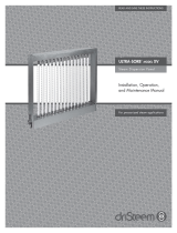
Ultra-sorb
®
Model XV
Steam Dispersion Panel
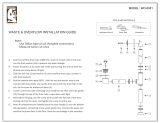
Installation, Operation,
and Maintenance Manual
For pressurized steam applications
USXV-IOM-0308.pdf 1 4/21/2010 11:35:32 AM

Page 2 • DRI-STEEM Ultra-sorb Model XV Steam Dispersion Panel Installation, Operation, and Maintenance Manual
Table of contents
Field assembly
Unpack the dispersion assembly and loose components ........ 3
Verify that the order is complete ............................ 3
Lay out the panel components .............................. 4
Attach the anges ......................................... 4
Attach the top frame assembly .............................. 4
Tighten the ange locknuts ................................. 4
Install the dispersion tubes ................................. 4
Installation
Panel and piping components ............................... 5
Selecting the location ...................................... 6
Installation in a cold air stream ............................. 7
Placement upstream of an elbow or duct split ................. 7
Installation above valuable equipment ........................ 7
Recirculation unit ......................................... 7
Panel support ............................................. 7
Dispersion tube orientation ................................. 8
Mounting in a duct ........................................ 8
Duct smoke detector ....................................... 8
Mounting in an air handling unit ............................ 9
Trap recommendation .................................... 10
Recommendations for steam absorption ..................... 10
Steam and condensate connections ......................... 10
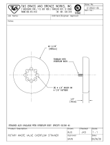
Header overow P-trap water seal .......................... 10
Preventing duct static pressure loss ......................... 11
Lifting condensate ........................................ 11
Temperature switch ....................................... 12
Heat exchanger shut-o delay .............................. 12
Start-up and operation .................................... 13
Performance data ......................................... 14
Maintenance
Strainer ................................................. 15
Steam traps .............................................. 15
Header overow P-trap water seal .......................... 15
Valves .................................................. 15
Dispersion tubes ......................................... 15
Heat exchanger .......................................... 16
Replacement parts ........................................ 17
Troubleshooting ........................................... 18
Warranty .................................................. 20
ATTENTION INSTALLER
Read this manual before installing.
Leave manual with product owner.
DRI-STEEM technical support
800-328-4447
WARNING!
Steam humidification systems have
extremely hot surfaces.
To avoid burns, allow humidifier,
steam pipes, and dispersion
assemblies to cool before touching
any part of the system.
USXV-IOM-0308.pdf 2 4/21/2010 11:35:39 AM

DRI-STEEM Ultra-sorb Model XV Steam Dispersion Panel Installation, Operation, and Maintenance Manual • Page 3
Field assembly
CAUTION!
The dispersion tubes are sleeved in clear poly film
for protection during processing, shipping, and
installation.
Leave the clear poly film on until installation is
complete so the insulation stays clean.
Equally important, remove and discard the clear
poly film before start-up by tearing it along the
perforations. Do not remove the white PVDF
insulation.
Unpack the dispersion assembly and loose components
• Ultra-sorb Model XV has high-efficiency dispersion tubes.
The tubes are insulated with polyvinylidene fluoride (PVDF)
insulation, which provides up to an 85% reduction in wasted
energy by significantly reducing airstream heat gain and
condensate production.
• Remove shipping materials from the dispersion assembly, being
careful not to bump or scrape the white PVDF dispersion tube
insulation
• Do not lay dispersion tubes (if shipped loose by request or by
shipping necessity) across or under anything that could compress
or damage the insulation. Compressing insulating material may
reduce its R-value.
• Avoid bumping or snagging the PVDF insulation. Although
PVDF is robust, rough handling can cause tears, which could
negatively impact performance.
• Before start-up, remove the clear poly film by tearing it along the
perforation.
Do not use a knife or sharp object to remove the poly
film. Do not remove the white PVDF insulation.
Verify that the order is complete
Verify that all panel and piping components are included in the
delivery. Check the packing list, and see Tables 4-1 and 5-1.
• Keep the flame away from the insulating
material to avoid damage.
• PVDF is inherently resistant to UV light.
Indirect, low-intensity UV-C light from
germicidal lamps will not cause the
insulating material to degrade.
• Do not tighten mounting clamps or
fasteners to any part of the dispersion
tube.
Integral heat exchanger
• Ultra-sorb Model XV employs an integral
heat exchanger to pressurize and lift
condensate up to 12" per psi (300 mm
per 6.9 kPa) of steam pressure.
• Steam pressure entering the heat
exchanger must be at least 5 psig
(35 kPa).
• Condensate may be piped to the
condensate return main.
USXV-IOM-0308.pdf 3 4/21/2010 11:35:39 AM

Page 4 • DRI-STEEM Ultra-sorb Model XV Steam Dispersion Panel Installation, Operation, and Maintenance Manual
Field assembly
Lay out the panel components
Orient the panel components on a large, flat working surface.
Attach the flanges
Guide the flanges onto the threaded studs of the header assembly,
and start the locknuts onto the threads finger-tight.
Attach the top frame assembly
Span the flanges with the top frame assembly. Align the locating
buttons on the flanges and top frame, and push the eight panel
fasteners into place.
Note: Compress the toggles to remove a panel fastener.
Tighten the flange locknuts
Torque the eight flange locknuts to 16 ft-lb (22 N-m) at 100 rpm
maximum using a 7/16" deep-well socket.
Install the dispersion tubes
Note: Do not remove the poly film from the dispersion tubes until
after the panel is installed.
Ensure that each dispersion tube has the seal and spring in place (
see
Figure 5-2)
. Push the dispersion tube plug end into the top frame
hole to compress the spring. Seat the seal end in the corresponding
header hole on the bottom. Rotate the dispersion tubes so the
tubelets discharge steam perpendicular to the airstream. See
Figure 8-1.
Header assembly
Figure 4-1:
Model XV components
Table 4-1:
Model XV panel components
Component Qty.
Header assembly 1
Dispersion tube Varies
Top frame assembly 1
Flanges 2
Panel fasteners 8
Flange locknuts 8
Flange locknut
Panel fastener
Flange
OM-7484
Top frame assembly
Dispersion tube assembly
Note: These assembly instructions are for
Ultra-sorb Model XV panels shipped
unassembled by request or as required.
Panels with overall height more than
98" (2490 mm) are shipped unassembled.
USXV-IOM-0308.pdf 4 4/21/2010 11:35:39 AM

DRI-STEEM Ultra-sorb Model XV Steam Dispersion Panel Installation, Operation, and Maintenance Manual • Page 5
Installation
Panel and piping components
The Ultra-sorb Model XV dispersion panel and piping components
are shown in
Figure 5-1.
Panel location choices, installation instructions, and system options
are provided in the following subsections.
Figure 5-1:
Piping components
OM-7494
Table 5-1:
Piping components
Component Qty.
Modulating steam valve 1
On/Off valve for pressurized steam input 1
Temperature switch 1
Inlet strainer 1
Float & thermostatic (F&T) trap 1
From pressurized
steam source
Modulating steam valve
To condensate return main
Temperature
switch
On/off valve
Inlet strainer
F&T trap
Model XV steam dispersion panel
Dashed lines indicate provided by installer.
F&T trap
Figure 5-2:
Dispersion tube
Spring
Plug
Ring
Seal
OM-7484
Insulation
Install
this
end
up
To condensate return main
Access port and overflow
(see Figure 11-1)
USXV-IOM-0308.pdf 5 4/21/2010 11:35:40 AM

Page 6 • DRI-STEEM Ultra-sorb Model XV Steam Dispersion Panel Installation, Operation, and Maintenance Manual
Selecting the location
DRI-STEEM has
cataloged the distance unabsorbed steam travels in
an
airstream (see Figure 15-1). Dispersed steam must be absorbed
into the airflow before it comes in contact with duct elbows,
fans, vanes, filters, or any object that can cause condensation and
dripping.
A. Install the Ultra-sorb panel in a location where discharged water
vapor being will be absorbed by the airstream.
B. In general, place the Ultra-sorb panel where the air tempera
-
ture is capable of absorbing discharged steam without causing
condensation at or after the unit. This will normally be down
-
stream of the heating coil where the air is warmest.
C. Do not place the Ultra-sorb panel in an outside air intake unless
the air is tempered with a preheat coil.
D. Do not place the Ultra-sorb panel near the entrance of a
high-efficiency filter. The filter will remove visible moisture
and become waterlogged. See the CAUTION about absorption
(non-wetting) distance in the Performance data section.
E. Do not place the Ultra-sorb panel where discharged visible mist
will impinge directly on a metal surface.
Installation
Outside air
Relief air
Preheat coil
Motorized
air dampers
Supply airflow
Filters
Economizer
control device
Heating coil
Cooling coil
8' to 12' (2.4 to 3.7 m)
Duct high limit humidity control for dispersion
locations A, B
Airflow proving switch
Airflow proving switch
Duct high limit humidity control
for dispersion location C
Return airflow
8' to 12'
(2.4 to 3.7 m)
3' to 5'
(1 to 1.5 m)
Fan
Figure 6-1:
Placing a dispersion assembly in an AHU
ABD
C
Exterior
building wall
Panel placement in an air handling unit
(see Figure 6-1)
•
Location A is the best choice.
Installing downstream of heating and cooling
coils provides laminar flow through the disper-
sion unit; plus, heated air provides an environ-
ment for best absorption.
• Location B is the second-best choice.
However, in change-over periods, the cooling coil
will eliminate some moisture for humidification.
• Location C is the third-best choice.
Air leaving a fan is usually very turbulent and
can cause vapor to not absorb at the expected
absorption distance. Allow for more absorption
distance if installing downstream of a fan.
•
Location D is the poorest choice.
The cooler air at this location requires an
increased absorption distance.
DC-1081
USXV-IOM-0308.pdf 6 4/21/2010 11:35:41 AM

DRI-STEEM Ultra-sorb Model XV Steam Dispersion Panel Installation, Operation, and Maintenance Manual • Page 7
Installation
Elbow
Duct
Airflow
Airflow
Ultra-sorb
Ultra-sorb
Duct split
Figure 7-3:
Upstream placement
Non-wetting
distance from
Figure 14-1
Cold
airflow
Ultra-sorb
Extended trails of
fog may develop
High-limit duct humidistat 10-15 feet
(3-4 m) downstream from Ultra-sorb
Figure 7-2:
Installation in a cold air stream
Installation in a cold air stream
When a humidifier is installed in a duct that will carry cold air,
determine the dew point temperature. If the psychrometric chart
reveals that saturation may occur, protection should be provided. A
high-limit humidistat or thermostat set to cut off the humidifier at a
safe temperature can be used for this purpose. See Figure 7-2.
Placement upstream of an elbow or duct split
Due to Ultra-sorb's rapid steam absorption performance,
installation upstream from elbows or duct splits can be done with
confidence. See Figure 7-3.
Installation above valuable equipment
Water piping and humidifiers should not be installed above
expensive equipment. A condensing or leaking water pipe or
other accidental water spillage could cause serious damage to the
equipment below. When such an installation cannot be avoided,
install a galvanized drip pan under the humidifier piping, valve, etc.
to catch and drain away unintended water. See
Figure 7-4.
See the Header overflow P-trap water seal section.
Recirculation unit
In applications where no duct system exists, or if the air is too cool
for proper humidity absorption, a recirculation fan can be used.
The fan circulates room temperature air across the humidifier and
discharges humidified air into the space. Select the air discharge
point carefully to avoid condensation on building or equipment
surfaces. See Figure 7-1.
Panel support
The duct or air handler section and Ultra-sorb panel must be
properly supported to carry the weight of the assembly. The weight
of the piping must be supported by the building structure rather
than by the Ultra-sorb unit. Otherwise, the weight may impose
stress on the connections, causing them to fracture and leak.
Ultra-sorb
Airflow
Drip pan
Pipe to drain size as required
Ceiling line
Vapor
absorption
area
* This duct length should have sealed seams and should
be at least three times the published non-wetting
distance.
Ceiling line
Ultra-sorb
Airflow
Blower
Figure 7-4:
Installation above valuable equipment
2" (50 mm)
Figure 7-1:
Recirculation unit
*
Vapor
absorption
area
*
* This duct length
should have sealed
seams and should
be at least three
times the published
non-wetting
distance.
OM-197
OM-178
OM-198
OM-179
USXV-IOM-0308.pdf 7 4/21/2010 11:35:42 AM

Page 8 • DRI-STEEM Ultra-sorb Model XV Steam Dispersion Panel Installation, Operation, and Maintenance Manual
Installation
Dispersion tube orientation
Verify that the steam discharge tubelets are perpendicular to the
airstream (see Figure 8-1). The spring-loaded dispersion tubes
easily rotate for proper orientation.
Figure 8-2:
Model XV in a duct
OM-7490
Airflow
Tubelet
Figure 8-1:
Dispersion tube orientation
Dispersion tube
Mounting in a duct
To avoid puncturing the header, screw penetration into the
header assembly must not exceed ¾" (20 mm).
The Model XV panel is designed for horizontal airflows only.
Mounting flanges on both sides of the unit and the header and
frame can be used as mounting surfaces (see Figure 8-2). A
matching flange or metal frame is required on the ductwork for
connection to the Ultra-sorb flanges. The recommended fastener is
a #12 self-drilling and tapping screw ¾" (20 mm) long, spacing not
to exceed 12" (305 mm). If an angle-iron frame is provided on the
duct section, a longer screw may be required.
Airflow
Attach duct flange to
top frame assembly
1/2" (13 mm)
1/2" (13 mm)
Screws OK
ws OK
ws
OK
Attach duct flanges
to 1.5" (38 mm)
mounting flanges
Slope header toward steam inlet 1/16" per foot (1 mm per 190 mm) maximum
Attach duct
flange to header
assembly
Screws OK
No screws
No screws
OM-150a
Duct smoke detector
Do not install a duct smoke detector downstream
from the Ultra-sorb panel. If downstream
installation is required, install it far enough from
the Ultra-sorb panel to avoid false alarms.
Figure 8-3:
Preventing duct static pressure loss
Top
outside
corners
Four inside
corners
Both sides of
cover seam
Perimeter of top frame
along duct flange
OM-7483
Ultra-sorb panels that penetrate a duct section must
be sealed with HVAC caulking or a similar weather
sealant to prevent air leakage.
USXV-IOM-0308.pdf 8 4/21/2010 11:35:42 AM

DRI-STEEM Ultra-sorb Model XV Steam Dispersion Panel Installation, Operation, and Maintenance Manual • Page 9
Installation
Mounting in an air handling unit
Model XV must be used in pressurized steam applications and in
horizontal airflows only, as shown in Figure
9-1.
Metal support frames should be anchored to the air handler casing.
Recommended fasteners for mounting the Ultra-sorb to a metal
support frame are ¼ - 20 nuts and bolts or #12 self drilling and
tapping screws.
Due to possible forces exerted on this application, DRI-STEEM
recommends fastener spacing not to exceed 6" (150 mm).
Figure 9-1:
Model XV in an air handler
Tubelets perpendicular to airflow
Header
Humidification
steam in
Pressurized condensate out to return mainPressurized steam into
heat exchanger*
OM-7489
From
pressurized
steam source
Install strainer
within 3' (1 m)
of Ultra-sorb
AHU wall
AHU width
AHU
height
Coil width
Coil
height
Modulating steam valve
Temperature switch
F&T trap
On/Off solenoid valve
Tub
ele
ts
per
pen
dic
u
Dashed lines indicate provided by installer.* Minimum steam pressure 5 psig (35 kPa)
Slope header toward steam inlet 1/16"
per foot (1 mm per 190 mm) maximum
Connection end of header
Pressurized
steam in*
Pressurized
condensate
out
Access port and
overflow
Humidification
steam in
Optional header
overflow P-trap
water seal
Priming filler cap
USXV-IOM-0308.pdf 9 4/21/2010 11:35:43 AM

Page 10 • DRI-STEEM Ultra-sorb Model XV Steam Dispersion Panel Installation, Operation, and Maintenance Manual
Installation
Trap recommendation
The steam supply line should be dripped immediately ahead of the
steam valve through a steam trap.
Low pressure, up to 15 psi (103 kPa) — F&T trap
High pressure, more than 15 psi (103 kPa) — Inverted bucket trap
Install a wye strainer ahead of the steam valve (see Figure 10-1).
Recommendations for steam absorption
To ensure driest steam, take humidifier steam off the top of the
steam main (not the side or bottom).
An airflow proving switch is recommended to prevent the steam
valve from opening if air is not moving in the duct.
To prevent over saturation when duct air is cooler than 70 °F
(21 °C), a high-limit (duct mounted) humidistat at least 15 feet
(4.5 m) downstream and set at 80-90% is recommended.
Steam and condensate connections
Use a back-up wrench when tightening connections onto any
Ultra-sorb threads (see Figure 10-2).
Humidification steam inlet
Because the heat exchanger vaporizes all dispersion tube-
generated condensate, all steam entering the humidification steam
inlet exits the tubelets and is dispersed in the airstream.
Pressurized boiler steam inlet
Steam pressure entering the heat exchanger must be least 5 psig
(35 kPa) to vaporize condensate in the header.
Pressurized condensate outlet
Condensate exiting the heat exchanger is piped to the condensate
return main. See Lifting condensate on the facing page.
Header overflow P-trap water seal
Ultra-sorb Model XV is designed to vaporize the condensate
generated in a properly designed, installed, operated, and
maintained system. An optional, fail-safe header overflow
installation is recommended if any of the following are true:
• Operating parameters exceed design criteria.
• Boiler chemicals are causing heavy material deposition on the
heat exchanger (see Heat exchanger in the Maintenance section).
• System overflow prevention is critical.
Figure 10-2:
Steam and condensate connections
Humidification
steam inlet
1” or 2” NPT,
internal thread
Pressurized boiler
steam inlet
3/4” NPT, internal
thread
Pressurized
condensate outlet
3/4” NPT, internal
thread
Access port and overflow
1/2” NPT, internal thread
Figure 10-1:
Ultra-sorb strainer
Install strainer same size as valve
and within 3' (1 m) of Ultra-sorb
Valve
From pressurized
steam source
DC-1097
OM-7482
USXV-IOM-0308.pdf 10 4/21/2010 11:35:43 AM

DRI-STEEM Ultra-sorb Model XV Steam Dispersion Panel Installation, Operation, and Maintenance Manual • Page 11
Installation
• The application requires the tallest dispersion tubes, the closest
tube spacing, and the lowest allowable heat exchanger steam
pressures.
• Operator intervention could result in improper system settings.
The access port can be configured as a header overflow with a
P-trap water seal. To install an overflow P-trap and drain line,
replace the access port 1/2" NPT plug with a 1/2" NPT drain
connection, and plumb the drain pipe dimensions as shown in
Figure 11-1.
Before operating the Ultra-sorb, prime the P-trap with about 1 cup
(200 ml) of water. During normal operation, little condensate is
available to the overflow. As such, a water seal cannot be assured via
condensate alone. At startup after long off periods:
• Air may be drawn into the duct via the overflow drain for some
time before a water seal forms.
• Steam may blow through the overflow drain for some time before
creating a water seal.
If either of these scenarios are unacceptable, prime the P-trap before
seasonal startup, or feed the P-trap with a water source that assures
a constant water seal.
Lifting condensate
Theoretically, 1 psi of steam pressure will lift condensate about 28"
(6.9 kPa will lift condensate about 700 mm). In practice, because of
pipe friction, pressure drop through a steam trap, and back pressure
in a return line, a maximum lift of 12" per psi (300 mm per 6.9 kPa)
of steam pressure at the trap is recommended.
The steam trap for lifting condensate should be an inverted bucket
type with a check valve on the outlet. Float and thermostatic traps,
are prone to damage from water hammer often present in flooded
trap conditions where condensate must be lifted.
The vertical portion of the piping should be at least 1/2" NPT.
Figure 11-1:
Header overflow P-trap water seal
12" (305 mm) seal
After the water seal, run a 1½" (DN40) drain line
to an open drain with a 1" (25 mm) air gap.
OM-7493
Access port and overflow
(connection for the P-trap
overflow water seal)
Connection end of header
1.25" (32 mm) rise
10.75" (273 mm)
Fill cap
USXV-IOM-0308.pdf 11 4/21/2010 11:35:43 AM

Page 12 • DRI-STEEM Ultra-sorb Model XV Steam Dispersion Panel Installation, Operation, and Maintenance Manual
Installation
Temperature switch
Install the temperature switch to prevent the header from flooding
with condensate if the heat exchanger cools, such as if the
condensate return main becomes flooded or the P-trap fails closed.
DRI-STEEM's electric temperature switch prevents the header from
flooding with condensate if the heat exchanger cools by means of
a temperature-actuated make-break switch designed for electric
humidity control systems. The temperature at which it switches is
adjustable and should be set at 210 °F (99 °C).
• Install the sensing element of the device in the condensate return
piping between the Ultra-sorb heat exchanger outlet and the inlet
to the steam trap, as shown in Figure
12-1. Include a tee with
a ½" (DN15) pipe thread opening to receive the sensing element.
When steam surrounds the sensing element, the switch will
“make,” allowing the humidifier valve to open.
• Install all wiring according to national and local electrical codes,
and size transformer VA to load VA.
• When using the temperature switch with an electric modulating
valve, use the special wiring instructions furnished with the valve.
Figure 12-1:
Temperature switch location
To condensate
return main
Temperature switch
On/off valve
F&T trap
From
pressurized
steam source
Heat exchanger shut-off delay
To dry the header, pressurized steam can be set to flow through the
heat exchanger for a set amount of time after humidification steam
stops. This time delay can be set through the building management
system (BMS) or configured independent from the BMS. See the
wiring diagram included with the on/off valve.
A time delay relay for configuring the time delay manually is
available from your local DRI-STEEM representative.
For systems that run constantly (all day, every day, all year), there is
no need for a shut-off delay.
Systems that stop humidifying for extended periods of time may
have two reasons for a heat exchanger shut-off delay: to conserve
energy and to remove standing water that might allow for microbe
growth.
Setting the heat exchanger to remain on for 1/2 hour after
humidifying stops will be adequate time to ensure complete dry-out
of the dispersion system.
OM-7477
USXV-IOM-0308.pdf 12 4/21/2010 11:35:44 AM

DRI-STEEM Ultra-sorb Model XV Steam Dispersion Panel Installation, Operation, and Maintenance Manual • Page 13
Start-up and Operation
After removing the clear poly film from the dispersion tubes, follow
the start-up instructions below.
Start-up
1. Prime the header overflow P-trap, if installed, and ensure that
it follows the recommendations in the Header overflow P-trap
water seal section and Figure 11-1.
2. Turn on steam to the heat exchanger. Inspect connections for
piping leaks.
3. Ensure that the traps are operating.
4. Turn on the modulating steam valve, and check for piping leaks.
5. Check the dispersion tubes for leaks.
Note: Spitting from the seal (bottom) end of a dispersion tube
could be caused by a missing seal (5). See Figure 17-1.
6. Ensure that the dispersion tubes are oriented with the tubelets at
a right angle to the airflow. See Figure 8-1.
7. Check for any other leaks from header connections.
8. With both heat exchanger and humidification steam turned
on, turn off steam to the heat exchanger. Make sure the
temperature switch turns off the modulating steam valve to stop
humidification steam from entering the dispersion assembly.
9. Heat exchanger operation:
• Ensure operating steam pressure is at least 5 psig (35 kPa).
• Ensure on/off and shut-off delay (if using shut-off delay)
conditions are working as intended.
Operation
During operation, prevent problems by following the service time
intervals and guidelines in the Maintenance section. See Table 18-1
for troubleshooting.
Do not remove the white PVDF
insulation.
Tear the clear poly film along the
perforations, and remove and discard it
before start-up.
USXV-IOM-0308.pdf 13 4/21/2010 11:35:44 AM

Page 14 • DRI-STEEM Ultra-sorb Model XV Steam Dispersion Panel Installation, Operation, and Maintenance Manual
Performance data
1. Non-wetting distance is the distance downstream from the
Ultra-sorb panel after which wetting will not occur. Although
steam wisps may be present, solid objects at duct air tempera-
ture, such as coils, dampers, fans, etc., downstream from this
point will remain dry.
2.
See Figure 14-1. Note that the rise in RH (ΔRH) between
entering and leaving air has a direct bearing on the non-wetting
distance. As the
ΔRH increases, more vapor needs to be
dispersed into the air; thus, the non-wetting distance increases.
3.
CAUTION! Non-wetting distances described here do not apply
when installing an Ultra-sorb panel upstream of filter media. If
you must install an Ultra-sorb panel upstream of filter media,
consult DRI-STEEM or your local DRI-STEEM representative
for special recommendations.
4.
Uneven airflow over the Ultra-sorb panel cross-section may
result in nonuniform mixing of steam with air, which may
adversely affect absorption distance.
5. A small but measurable amount of duct air pressure loss will be
present downstream from the Ultra-sorb panel, depending on air
density, velocity, and tube spacing. See Table
14-1.
NON-WETTING DISTANCE IN INCHES
3" 6" 9" 12"
Figure 14-1:
Ultra-sorb non-wetting distances
Table 14-1:
Model XV air pressure loss
Duct air
velocity
(55 ˚F [13 ˚C] at
sea level)
Tube spacing
3" 75 mm 6" 150 mm
fpm m/s wc Pa wc Pa
500 2.54 0.033 8.3 0.005 1.3
1000 5.08 0.121 30.2 0.020 5.1
1500 7.62 0.237 59.2 0.046 11.5
Notes:
• Ultra-sorb panels with 9" (225 mm) or 12" (300 mm)
tube spacings have no measurable air pressure loss.
• Use DRI-STEEM’s Dri-calc sizing and selection software
to calculate your specific air pressure loss.
Note:
The above non-wetting data apply to air velocities up to 2000 fpm (10.2 m/s) and are based on air leaving the humidification zone at of 55 °F (13 °C) and the stated % RH.
USXV-IOM-0308.pdf 14 4/21/2010 11:35:44 AM

DRI-STEEM Ultra-sorb Model XV Steam Dispersion Panel Installation, Operation, and Maintenance Manual • Page 15
Maintenance
Strainer
Inspect at least twice during the first year. If fouled, inspect it more
frequently.
Steam traps
At least twice a year verify that the steam traps are functioning
properly. A blocked steam trap is room temperature. A “blowing”
steam trap is hot and noisy, and the discharge pipe from it is hot
for 30 feet (9 m). A properly operating steam trap is hot and makes
noise at intervals, and the discharge pipe is progressively cooler
beginning at the trap.
Header overflow P-trap water seal
If this option is used (see Header overflow P-trap water seal in the
Installation section): P
rime the P-trap with about 8 ounces (about
200 ml) of water whenever the panel has been idle for 90 days or
more.
Valves
• Pneumatic: Inspect annually to be sure the valve tightly closes off
steam, the stem packing is not leaking steam, and the actuator
diaphragm is not leaking air.
• Electric modulating: Inspect annually to be sure the valve oper
-
ates freely and closes off steam tightly and the
stem packing is
not leaking.
• Solenoid type: Inspect annually to verify proper functioning with
steam-tight shut off.
Dispersion tubes
• If steam or condensate is evident at the sealing surface, replace
the seal.
• Inspect insulating material for tears; repair with Insulating
Material Repair Kit (available from your local DRI-STEEM
representative) before dispersing steam or moving air through
the air handler to prevent further damage. This kit uses tested
and proven PVDF as repair material; do not use other adhesives
or repair methods.
• Inspect insulating material for dirt and smudges; gently clean
with damp cloth and soapy water or diluted nontoxic, biodegrad-
able cleaner/degreaser. Do not clean insulating material with a
pressure washer; direct spray could cause damage.
USXV-IOM-0308.pdf 15 4/21/2010 11:35:44 AM

Page 16 • DRI-STEEM Ultra-sorb Model XV Steam Dispersion Panel Installation, Operation, and Maintenance Manual
Maintenance
Heat exchanger
Environmental conditions may require periodic heat exchanger
cleaning. After 2000 hours of operation, remove a dispersion tube and
check whether the heat exchanger is coated with material deposits.
Use of boiler chemicals that result in material deposits on the heat
exchanger may require more frequent inspection and cleaning to
maintain proper heat exchanger operation and avoid header flooding.
Material deposits can be removed from the heat exchanger with
DRI-STEEM’s Humidifier De-scaling Solution, available for purchase
from your DRI-STEEM representative or distributor. It is the only
cleaner/de-scaler approved for use with DRI-STEEM humidifiers.
Use of other cleaners/de-scalers may void your DRI-STEEM
warranty. See DRI-STEEM’s Humidifier De-scaling Solution page at
www.dristeem.com, or click here.
The Usage Instructions shipped with the DRI-STEEM Humidifier
De-scaling Solution contain important handling, mixing, timing, and
pH testing information.
The following additional instructions are for Ultra-sorb Model XV:
• Before pouring water or de-scaling solution into the header, install a
1/2" NPT thread drain hose in the header access overflow port. After
making sure the hose can reach a bucket or drain, elevate the end
well above the connection.
• Remove a dispersion tube, and add water to the header to submerge
the heat exchanger (see Figure 16-2).
• Add 10 ounces of de-scaling solution per foot of header length
(30 ml of de-scaling solution per 300 mm of header length). A
12-foot (3660 mm) header requires about 1 gallon (3.8 litres) of de-
scaling solution.
• After performing the de-scaling procedure as described in the Usage
Instructions: Before resuming operation, flush and drain the header
four times to thoroughly remove de-scaling solution from the system.
WARNING!
Read and follow all warnings and instructions shipped with the
DRI-STEEM Humidifier De-scaling Solution.
Figure 16-2:
Header cross section
Pour water into
header through
dispersion tube
hole; submerge heat
exchanger
Heat exchanger
OM-7492
Fill water
USXV-IOM-0308.pdf 16 4/21/2010 11:35:44 AM

DRI-STEEM Ultra-sorb Model XV Steam Dispersion Panel Installation, Operation, and Maintenance Manual • Page 17
Table 17-1:
Model XV Replacement parts
No. Description Part No.
1 Panel fastener, frame (package of 4)
191170-010
2 O-ring, square 1.35" ID (package of 10) 191170-015
3
Ring, tube end, 1.5" (package of 1) 207010-001
Ring, tube end, 1.5" (package of 5) 191170-020
4
Spring, compression, SST (package of 1) 501460-001
Spring, compression, SST (package of 5) 191170-025
5
Plug, tube end, 1.5" (package of 1) 310260
Plug, tube end, 1.5" (package of 5) 191170-030
6 Dispersion tube assembly consult factory
7 Flange, side consult factory
8 Frame assembly, top consult factory
9 Header assembly consult factory
10 Nut, 1/4-20 (package of 4) 191170-035
11 HVAC sealant for duct section applications (not shown) consult factory
Replacement parts
Figure 17-1:
Model XV replacement parts
OM-7484
5
1
4
3
2
10
7
8
7
9
6
Table 17-2:
Replacement components
Description Part No.
Modulating steam valve consult factory
On/Off valve body 501750-001
On/off valve coil 501700-002
Temperature switch 400260-001
Inlet strainer consult factory
F&T trap consult factory
USXV-IOM-0308.pdf 17 4/21/2010 11:35:44 AM

Page 18 • DRI-STEEM Ultra-sorb Model XV Steam Dispersion Panel Installation, Operation, and Maintenance Manual
Troubleshooting
Table 18-1:
Model XV troubleshooting guide
Problem Possible cause Action
Humidifier discharges water
in duct
• Missing or torn seal • Replace seal.
• Dispersion tube not properly installed • Ensure proper installation. See Figure 5-2.
• Humidification steam is exceeding capacity per tube • Ensure humidification is 35 lbs/hr (15.8 kg/h) per tube or less.
• Steam main overloaded with water due to boiler
discharging water with steam (priming)
• Locate cause of priming and correct.
• Steam trap not draining properly • Replace, repair, or clean trap as required.
• If condensate return main is overloaded, find an alternative method
for draining.
• Humidifier improperly piped • Correct piping as shown in Figure 5-1.
• Surges of condensate in steam supply due to conden-
sate collecting at low, undripped point in steam main
• Install drips and steam traps as required. See "Trap recommendation"
on page 10.
• Inadequate steam trap capacity • Replace with larger trap.
• Pressurized condensate is being lifted too high • See "Lifting condensate" on page 11.
• Heat exchanger is caked or dirty • Flush header. See "Heat exchanger" on page 16.
• Condensate collecting in header • Increase steam pressure through heat exchanger.
• See "Header overflow P-trap water seal" on page 10.
• On/off valve upstream from heat exchanger
malfunctioning or stuck in the OFF position
• Replace, repair, or clean valve as required.
• Temperature switch downstream from heat exchanger
malfunctioning
• Replace or repair switch as required.
Humidity exceeds setting of
humidistat
• Automatic valve not fully closing • Foreign matter holding valve open; clean valve.
• Valve spring broken; replace spring.
• Valve steam packing too tight; loosen and/or replace packing.
• Steam pressure exceeds close-off rating of valve spring;
replace actuator or valve spring with one that is compatible with the
higher steam pressure.
• Valve installed backwards; re-install.
• Adjust valve linkage.
• Electric control system malfunctioning • Calibrate or replace.
• Faulty or inaccurately placed humidity controller • Replace controller or relocate per catalog recommendations.
• Poor location of control components • Relocate per catalog recommendations.
• Incompatible control components • Replace per specified recommendations.
• Automatic valve is hunting • Humidifier capacity is oversized; change to smaller valve.
• Pressure reducing valve is not accurately controlling steam pressure;
repair or replace.
• Boiler pressure is swinging too widely; adjust.
• Excessive outside air volume • Check fans, dampers, VAV, etc.
• Mixed air inlet formula: (% outside air) x (moisture content)
+ (% return air) x (moisture content)
= mixed air inlet in lbs/100 cfm (kg/100 m
3
/h)
Control system
malfunctioning
• Incorrect control voltage • Replace transformer.
• Incorrect control signal • Replace components.
• Improper wiring connections • Rewire.
• Incorrect humidity sensor • Replace.
• Humidity controller out of calibration • Recalibrate.
USXV-IOM-0308.pdf 18 4/21/2010 11:35:45 AM

DRI-STEEM Ultra-sorb Model XV Steam Dispersion Panel Installation, Operation, and Maintenance Manual • Page 19
Troubleshooting
Table 19-1:
Model XV troubleshooting guide (continued)
Problem Possible cause Action
Air cannot absorb steam
quantity being discharged
• Humidifier operates when blower is off • Provide interlock.
• Valve is hunting • See "Automatic valve is hunting," on facing page.
• Air temperature in duct too low for steam
quantity being emitted
• Raise duct air temperature.
Humidifier is noisy • Steam pressure too high • Reduce pressure.
• Panel is vibrating • Tighten assembly and/or mounting hardware.
Duct loses static pressure
downstream from Ultra-sorb
panel
• Improper sealing where Ultra-sorb frame
penetrates duct
• Seal all panel corners and all cracks between panel and ducts/flanges. See
"Preventing duct static pressure loss" on page 11.
Space humidity will not rise
to humidistat set point
• Steam pressure too low • Increase.
• Manual steam valve partially closed • Open.
• Strainer screen partially clogged • Clean.
• Boiler pressure too low • Adjust control.
• Pressure reducing valve not accurately
controlling steam pressure
• Repair or replace.
• Boiler pressure swinging too widely • Adjust controls.
• Incorrect piping • Correct piping as shown in Figure 5-1.
• Undersized steam piping • Replace piping.
• Automatic steam valve not fully opening • Valve packing is adjusted too tightly, loosen/replace packing.
• Adjust valve linkage.
• Recalibrate humidistat.
• Electric control system malfunctioning • Change transformer.
• Incorrect control circuit voltage • Replace components to make all components compatible.
• Incorrect control signal • Replace components.
• Improper wiring • Rewire.
• Incorrect humidity sensor • Replace sensor.
• Humidity controller out of calibration/malfunctioning • Repair or replace.
• Malfunctioning humidifier temperature switch not
allowing humidifier valve to open
• Replace or readjust.
• Pneumatic control system malfunctioning • Repair or replace.
• Obstructed air line • Remove obstruction.
• Malfunctioning pneumatic temperature switch • Replace switch.
• Air leak in actuator • Repair or replace diaphragm.
• Compressed air pressure is too low • Adjust pressure.
• Temperature control switch not allowing
modulating steam valve to operate
• Install header overflow.
See "Header overflow P-trap water seal" on page 10.
• Consult DRI-STEEM to assess whether installed panel is correct for application.
Condensate collects in duct • Foreign matter preventing valve from closing • Clean or replace valve.
• Panel is mounted too close to internal devices
(dampers, turning vanes, etc.) in duct
• Move panel to a point further upstream of internal devices. See "Selecting
the location" in the "Installation" section and Figure 6-1).
• More dispersion tubes shortens non-wetting distance. Consult DRI-STEEM
to determine the total number of tubes required.
• Uninsulated duct passing through unheated area
(low duct surface temperature)
• Insulate ductwork.
USXV-IOM-0308.pdf 19 4/21/2010 11:35:45 AM

Page 20 • DRI-STEEM Ultra-sorb Model XV Steam Dispersion Panel Installation, Operation, and Maintenance Manual
Two-year limited warranty
DRI-STEEM Corporation (“DRI-STEEM”) warrants to the original
user that its products will be free from defects in materials and
workmanship for a period of two (2) years after installation or
twenty-seven (27) months from the date DRI-STEEM ships such
product, whichever date is the earlier.
If any DRI-STEEM product is found to be defective in material or
workmanship during the applicable warranty period, DRI-STEEM’s
entire liability, and the purchaser’s sole and exclusive remedy, shall
be the repair or replacement of the defective product, or the refund
of the purchase price, at DRI-STEEM’s election. DRI-STEEM shall
not be liable for any costs or expenses, whether direct or indirect,
associated with the installation, removal or reinstallation of any
defective product.
DRI-STEEM’s limited warranty shall not be effective or actionable
unless there is compliance with all installation and operating
instructions furnished by DRI-STEEM, or if the products have been
modified or altered without the written consent of DRI-STEEM, or
if such products have been subject to accident, misuse, mishandling,
tampering, negligence or improper maintenance. Any warranty
claim must be submitted to DRI-STEEM in writing within the
stated warranty period.
DRI-STEEM’s limited warranty is made in lieu of, and DRI-STEEM
disclaims all other warranties, whether express or implied,
including but not limited to any IMPLIED WARRANTY OF
MERCHANTABILITY, ANY IMPLIED WARRANTY OF FITNESS
FOR A PARTICULAR PURPOSE, any implied warranty arising out
of a course of dealing or of performance, custom or usage of trade.
DRI-STEEM SHALL NOT, UNDER ANY CIRCUMSTANCES BE
LIABLE FOR ANY DIRECT, INDIRECT, INCIDENTAL, SPECIAL
OR CONSEQUENTIAL DAMAGES (INCLUDING, BUT NOT
LIMITED TO, LOSS OF PROFITS, REVENUE OR BUSINESS) OR
DAMAGE OR INJURY TO PERSONS OR PROPERTY IN ANY
WAY RELATED TO THE MANUFACTURE OR THE USE OF
ITS PRODUCTS. The exclusion applies regardless of whether such
damages are sought based on breach of warranty, breach of contract,
negligence, strict liability in tort, or any other legal theory, even if
DRI-STEEM has notice of the possibility of such damages.
By purchasing DRI-STEEM’s products, the purchaser agrees to the
terms and conditions of this limited warranty.
mc_101707_1125
Form No. USXV-IOM-0308
Part No. 890000-160
DRI-STEEM Corporation
An ISO 9001: 2000 certified corporation
U.S. Headquarters:
14949 Technology Drive
Eden Prairie, MN 55344
800-328-4447 or 952-949-2415
952-229-3200 (fax)
European office:
Marc Briers
Grote Hellekensstraat 54 b
B-3520 Zonhoven
Belgium
+3211823595 (voice)
+3211817948 (fax)
E-mail: [email protected]
Continuous product improvement is a
policy of DRI-STEEM Corporation; therefore,
product features and specifications are
subject to change without notice.
DRI-STEEM and Ultra-sorb are registered
trademarks of DRI-STEEM Corporation
and are filed for trademark registration in
Canada and the European community.
Ultra-sorb is covered by the following
Patents, with additional patents pending:
United States Patent numbers 5,126,080;
5,277,849; 5,372,753; 5,376,312; 5,543,090
© 2008 DRI-STEEM Corporation
Expect quality from the industry leader
For more than 40 years, DRI-STEEM has
lead the industry with creative and reliable
humidification solutions. Our focus on
q
uality is evident in Ultra-sorb, which
features stainless steel construction and an
industry-leading two year warranty covering
all parts.
For more information
www.dristeem.com
For current product information,
please see the literature section of our
web site: www.dristeem.com
USXV-IOM-0308.pdf 20 4/21/2010 11:35:45 AM
/