Page is loading ...

Steam Humidifier
Models 1150 and 1160
Installation, Operation, and Maintenance Manual
Humidifier
READ AND SAVE THESE INSTRUCTIONS

PRODUCT OVERVIEW . . . . . . . . . . . . . . . . . . . . . . . . . . . . . . 3
Materials Provided and Not Provided . . . . . . . . . . . . . . . . . .
3
Electrical Specifications, Capacities and Weights . . . . . . . .
4
Dimensions. . . . . . . . . . . . . . . . . . . . . . . . . . . . . . . . . . . . . . . 5
Overview of Humidifier Operation
. . . . . . . . . . . . . . . . . . . . . 7
INSTALLATION
Wiring Diagrams . . . . . . . . . . . . . . . . . . . . . . . . . . . . . . . . . .
9
Setting Slide Switches
. . . . . . . . . . . . . . . . . . . . . . . . . . . . . 11
Choosing a Location for Humidifier Components . . . . . . . .
13
Distribution Tube Installation . . . . . . . . . . . . . . . . . . . . . . .
15
Mounting the Humidifier . . . . . . . . . . . . . . . . . . . . . . . . . . .
18
Field Wiring . . . . . . . . . . . . . . . . . . . . . . . . . . . . . . . . . . . . .
19
Airflow Proving Switch Installation
. . . . . . . . . . . . . . . . . . . 23
Supply Water and Drain Piping
. . . . . . . . . . . . . . . . . . . . . . 23
OPERATION
Start-up Proced
ure . . . . . . . . . . . . . . . . . . . . . . . . . . . . . . . . 27
MAINTENANCE
Inspect and Service the Humidifier
. . . . . . . . . . . . . . . . . . . 29
Off-season Shut Down Procedure
. . . . . . . . . . . . . . . . . . . . 31
TROUBLESHOOTING . . . . . . . . . . . . . . . . . . . . . . . . . . . . . . 32
REPLACEMENT PARTS . . . . . . . . . . . . . . . . . . . . . . . . . . . .
36
APPENDIX – ABSORPTION
DISTANCE CALCULATION
. . . . . . . . . . . . . . . . . . . . . . . . . . 38
WARRANTY . . . . . . . . . . . . . . . . . . . . . . . . . . . . . . . Back Cover
TABLE OF CONTENTS
ATTENTION INSTALLER
This product must be installed by qualified HVAC and
electrical contractors. Failure to do so voids product
warranty due to possible product misapplication.
This product must be installed in compliance with
local, state, and federal codes.
WARNING
1. 240 volts may cause serious injury or death from electrical
shock. Disconnect power before installing supply wiring.
2. Water temperature in excess of 140°F (60°C) may cause
serious injury due to burns. Allow unit to cool before
draining or removing chamber.
3. The humidifier chamber, distribution assembly, and all
connected hose or piping may contain or discharge hot
steam and/or hot water at 212°F (100°C). Discharged
steam is not visible. Contact with hot surfaces,
discharged hot water, or air into which steam has been
discharged may cause severe personal injury.
4. Water pressure greater than 80 psi (550 kPa) may cause
the humidifier to overflow.
5. Humidifier weighs up to 80 lbs when operating.
Improper mounting of humidifier may cause humidifier
to fall from wall or ceiling resulting in serious injury.
Mount humidifier to a structurally stable surface per the
instructions in this manual.
6. Failure to properly ground unit may result in property
damage due to fire, or serious injury or death from
electrical shock.
7. Failure to follow the instructions in this manual may
cause moisture to accumulate, which may cause
bacteria and mold growth or dripping water into building
spaces. Dripping water may cause property damage.
CAUTION
1. Do not set humidity higher than recommended.
Condensation damage may result.
2. Failure to follow the instructions in this manual
for installation of distribution tube, airflow
proving switch, and high humidity limit switch
may cause condensation damage.
2

PRODUCT OVERVIEW
Aprilaire Steam Humidifiers create steam by boiling water inside a steam chamber. This is accomplished by the transfer of energy
from electric heating elements to the water inside the chamber. A three-level water probe is used to determine when to turn on
and off a water fill valve in order to bring water into the chamber. Once the chamber is full and there is a call for humidity from
the Automatic Steam Humidifier Control, the heating elements will be energized causing the water to boil. The boiling water
creates steam which, due to the moderate pressurization of the chamber that comes from boiling, is forced through the vapor
hose and steam distribution tube into the duct system. As water is boiled off, the water level in the steam chamber will drop. The
water probe will sense when it reaches a low point and will cause the fill valve to open.
The process of boiling the water in the steam chamber will cause minerals and impurities in the water to drop out. Depending
on the hardness and quality of the water, this can create a substantial build-up within the steam chamber. The unit will drain the
chamber periodically to help clean the steam chamber and reduce the amount of cleaning required during maintenance.
Aprilaire Steam Humidifiers are controlled by an Automatic Steam Humidifier Control mounted in the return duct that will sense
the relative humidity (RH) in the return air. If the return air is below the RH setpoint, the control will send the humidifier a signal
to begin producing steam. Once this happens, the airflow proving switch (included) will check to ensure that the equipment
blower is operating. If the blower is not operating, the humidifier will send the equipment a signal to turn the fan on.
• The Aprilaire Steam Humidifier Model 1150, 12 lb/hr unit, features an Automatic Steam Humidifier Control with on/off control.
The on/off control will send a 10 VDC signal to the humidifier when the measured return air RH is 3% or more below setpoint
to turn the unit on at 100% output.
• The Aprilaire Steam Humidifier Model 1160, 24 lb/hr unit, features an Automatic Steam Humidifier Control with modulating
control. This control sends a signal between 0 and 10 VDC that is proportional to the difference between setpoint RH and
the measured return air RH. The signal for 100% humidifier output is 10 VDC and occurs at a control point that is adjustable.
The signal for 50% output is 5 VDC and occurs at the setpoint. The adjustable RH proportional control band can be set on the
board to 6%, 9%, 12% (default), or 15%. The humidifier uses this varying signal to time-proportion the operation of the heating
elements in the chamber.
The Automatic Steam Humidifier Control features an outdoor temperature sensor and is equipped to provide RH setpoint
compensation based on the actual outdoor temperature. When the weather gets colder outside, there can be problems with
condensation when introducing humidity into the building. The control recognizes this and adjusts the setpoint in the building to
a lower level. The control will still provide humidity to the building, but will not attempt to maintain a humidity level higher than
is appropriate for the current outdoor temperature. For applications that require specific set-point control, regardless of outdoor
temperature, the Control can be set up for manual operation. In Manual Mode, the outdoor temperature sensor is not used and
the RH is controlled to the specific setting on the Control.
MATERIALS PROVIDED MATERIALS NOT PROVIDED
1 Humidifier (Model 1150: 1 heater, 12 lbs/hr; Model 1160: 2 heater, 24 lbs/hr)
1 Distribution Tube (Model 1150: 10” active, 14” overall; Model 1160: 16” active, 20” overall)
1 10 ft. Steam Hose, 1
½” I.D.
1 1 ft. Drain Hose, 1” I.D.
2 Hose Clamps (for Steam Hose), 1
½” I.D.
2 Hose Clamps (for Drain Hose), 1” I.D.
2 Face Plates for Mounting Distribution Tube (1 set)
2 3/8” x 2” Lag Bolts for Mounting Humidifier
1 Automatic Steam Humidifier Control
1 Airflow Proving Switch
1 Installation, Operation, and Maintenance Manual
Electrical Supplies – quick disconnect box,
conduit, and wire (for power to the unit
and wiring to control devices)
Plumbing Supplies – supply and drain
piping, fittings, etc.
High Humidity Limit Switch
Hanging Brackets
(for mounting humidifier from ceiling)
3

OM-4006
Removable steam chamber
Immersion heaters
(1 in Model 1150, 2 in Model 1160)
Electrical power area
1½” (DN40) flexible steam hose
Duct
Electrical controls area
Power wiring knockout
¾” (DN20) copper
overflow and drain
Control wiring knockout
FIGURE 1 – Product Overview
TABLE 1 – Electrical Specifications
Model
number
Maximum
steam capacity
Current draw
(amps)
Circuit
Breaker
(amps)
minimum
kW
Shipping weight
(includes packaging and
all materials in the box)
Operating weight
(humidifier only, with
water in chamber)
Single-phase
lbs/hr kg/h 240V* lbs kg lbs kg
1150 12 5.4 16.7 25 4 70 32 67 30
1160 24 10.9 33.3 45 8 70 32 74 34
Note: Models 1150 and 1160 operate at 50/60 Hz.
* 208V single-phase may also be used but the steam capacity will be approximately 25% lower than the values above. It is recommended that the same size
circuit breakers be used with 208V single-phase as listed above for 240V.
Distribution Tube
Cover/shroud
Fill Valve
1/4” (DN8)
compression
fitting
Display panel
Field wiring terminal block
Internal controller board
4

OM-4018
FIGURE 2 – Dimensions (pertains to Models 1150 and 1160)
6.50”
(165 mm)
Venting
Chamber drain
Steam outlet
11.89”
(302 mm)
TOP VIEW
Power wire knockout
Control wire knockout
LEFT SIDE
VIEW
FRONT VIEW
BOTTOM VIEW
1.00” (25 mm)
3.09”
(78 mm)
24.06”
(611 mm)
Chamber fill
18.93”
(481 mm)
9.99”
(254 mm)
24.06”
(611 mm)
0.83” (21 mm)
1.19” (30 mm)
3.06” (78 mm)
1.37” (35 mm)
5.50”
(140 mm)
5

90-914
FIGURE 3 – Mounting Hole Locations
90-912, 90-913
FIGURE 4 – Distribution Tube Dimensions
6

INTERNAL CONTROLLER
The internal controller within the humidifier cabinet responds to external inputs (e.g., humidistat and airflow proving switch) and
internal inputs (e.g., water level probe inside the steam chamber) to provide:
• Relative humidity (RH) control
– Model 1150: With an on-off demand signal, the controller
maintains RH within 5% to 7% of set point.
– Model 1160: With a modulating demand signal, the
humidifier maintains RH within 2% to 4% of set point.
Modulating demand signal options include a 0–10 VDC
humidistat signal (humidistat provided), or a signal by
others (0–10 VDC or 4–20 mA).
• Automatic water level control and safety shut-down
If there is insufficient water, an electronic water level
probe sends a signal to the controller to add water or to
turn off the heaters.
• Operating time monitoring
The controller accumulates humidifier run time to activate
end-of-season draining, water cool-down, and auto draining.
• Automatic preheating
During chamber refilling, once there is enough water in
the chamber, the heaters energizes at 100% until the
water approaches boiling temperature to preheat the
chamber water so it is warm when the humidifier receives
a humidity demand signal.
• Automatic end-of-season draining
If the humidifier doesn’t receive a humidity demand signal
for 72 hours, the chamber automatically drains.
• Periodic drain and flush
To reduce mineral buildup in the chamber, the humidifier
automatically drains at intervals based on operating time,
output capacity, and water type. At the end of the drain
cycle, the supply water is brought on to briefly flush the
chamber.
• Chamber water cooling before draining
To ensure that water is at or below 140°F (60°C) before
discharging to the plumbing system, the humidifier remains
idle for a defined period of time before draining.
• Ensuring duct airflow
The humidifier will not make steam unless the HVAC
system blower is on and the airflow proving switch verifies
there is airflow in the duct.
OVERVIEW OF HUMIDIFIER OPERATION
DISPLAY PANEL AND INDICATOR LIGHTS
The display panel shows operating status and troubleshooting information. See the display panel detail (Figure 5) and the table
describing display panel lights (
Table 2). For more information about blinking indicator lights, see the troubleshooting section in
this manual.
OM-2028-M
On/Off
switch
Indicator
light
Steam
Fill Drain On/Off
FIGURE 5 – Display Panel
7

TABLE 2 – Display Panel Light Indications
Indicator light(s) Status Description
All
Blinking sequentially from
right to left
The humidifier is in a forced cool-down period prior to a required automatic drain sequence.
Normal operation
On/Off (switch)
On Power is on. Normal operation.
Slow blinking (1/sec.) The electronic water level probe needs cleaning.
Fast blinking (10/sec.) Probe logic fault. See Troubleshooting section.
Drain
On The humidifier is draining. Normal operation.
Blinking
The allowed amount of time for draining has been exceeded. Fault in drain operation.
Humidifier will continue to operate. See Troubleshooting section.
Fill
On The humidifier is filling. Normal operation.
Blinking
The allowed amount of time for filling has been exceeded. Fault in fill operation.
Humidifier will not operate. See Troubleshooting section.
Steam
On The humidifier is making steam. Normal operation.
Blinking
The humidifier has received a demand signal but cannot make steam because:
• There is not enough water in the chamber, or
• An enable/safety switch is open, or
Note:
See the Troubleshooting section in this manual for more information.
AUTODRAIN SEQUENCE MINIMIZES OUTPUT INTERRUPTIONS
The humidifier drains and flushes automatically at regular intervals to remove minerals from the chamber.
After the humidifier has run for a preprogrammed amount of time, and if there is no demand for humidity, the humidifier sits idle
until the chamber cools and then it drains.
If the humidifier has not completed an autodrain sequence due to continual demand signal interruptions, after an additional
amount of run time the humidifier begins a cool-down period and then it drains.
IMPORTANT: The humidifier attempts to complete an autodrain sequence when there is no demand for humidity. However,
if an autodrain sequence is not completed within a defined period of time, the humidifier ignores the demand signal until
completing an autodrain sequence. This could cause the relative humidity level in the humidified space to drop until the autodrain
sequence completes.
8

AA-LW420-1
FIGURE 6 – Model 1150 Wiring Diagram
INSTALLATION
APRILAIRE STEAM HUMIDIFIER MODEL 1150
SINGLE HEATER WIRING DIAGRAM
ON/OFF CONFIGURATION
9

AA-LW420-2
FIGURE 7 – Model 1160 Wiring Diagram
APRILAIRE STEAM HUMIDIFIER MODEL 1160
DUAL HEATER WIRING DIAGRAM
MODULATING CONFIGURATION
10

SETTING SLIDE SWITCHES
IMPORTANT: Slide switch on-off positions 1 through 16 are preset at the factory. These settings are determined
by output capacity, water type, and demand signal type. Changing these settings will affect humidifier operation.
Change on-off positions only per the instructions in this manual or as instructed by Aprilaire technical support staff.
On the internal controller inside the humidifier, there are two banks of slide switches. Most are set at the factory according to
the model type. Others, however, must be set according to the details of each particular installation. See Figure 8. Note: the ‘Off’
slide switch position is to the left while the ‘On’ slide switch position is to the right. For wiring details see page 21.
Type of Control Input
Model 1150 with an on/off control: S1 slide switch positions 1 and 2 Off
Model 1160 with modulating control: S1 slide switch positions 1 and 2 Off
Model 1160 with 0-10 VDC signal by others: S1 slide switch positions 1 and 2 Off
Model 1160 with 4-20 mA signal by others: S1 slide switch positions 1 and 2 On
Inlet water type
The controller allows autodrain settings for three water supply types:
• Normal water (hardness greater than 4 and less than
10 grains/gallon)
• Hard water (hardness greater than or equal to 10 grains/gallon)
• Softened water (hardness less than or equal to 4 grains/gallon)
The humidifier is preprogrammed for use with normal water. If your
water supply is hard or softened, follow the instructions below:
• For hard water supply (greater than or equal to 10 grains/gallon
of hardness):
– Set switch S1 position 3 to On; position 4 remains Off.
See Figure 8.
• For softened water supply:
– Set switch S1 position 4 to On; position 3 remains Off.
See Figure 8.
Substituting a remote fault alarm for blower starting
The humidifier may be field programmed to send a fault alarm signal
to a remote device instead of sending a signal to start the HVAC
equipment blower.
To enable this function, set slide switch S2 position 9 to On and
provide wiring to control terminals NO, O, and NC. See Figure 8
for slide switch positions.
If you change any on-off settings, record them in Table 3
for future reference.
Note:
Slide switches are shown in the off position.
LED lamp
Mounting hole
Position
S1
S2
OM-2038
FIGURE 8 – Slide Switches
Internal Controller Board
11

TABLE 3 – Factory Slide Switch Settings
Slide switch S1 Slide switch S2
Position Factory setting My setting Position Factory setting My setting
1 Off 9 Off
2 Off 10
See Table 4
Do not change.
3 Off 11 Off Do not change.
4 Off 12 Off Do not change.
5
See Table 4
Do not change. 13 Off Do not change.
6 Off Do not change. 14 Off Do not change.
7 Off Do not change. 15 Off Do not change.
8 Off Do not change. 16 Off Do not change.
Note: Positions 5-8 and 10–16 are for factory use only.
TABLE 4 – Slide Switch S1 Settings by Model
Model
Position
5 10
1150 Off On
1160 On Off
12

Humidifier Location
When selecting the location of the humidifier, consider the following:
• Proximity to duct
To avoid having to install a drain at the distribution tube in the duct, the distribution tube must be mounted at an elevation
higher than the humidifier. A 10’ (3 m) length of vapor hose is provided with the unit. The hose can be cut if less than 10’ (3 m) is
needed. The hose must have a constant downward slope from the distribution tube to the humidifier of at least 2”/ft (15%). If the
distribution tube must be installed at an elevation lower than the humidifier, install a drip tee and drain as shown in Figure
23.
• Required clearances (see Figure 9
)
• Electrical connections
Electrical power supply, water supply piping, and drain piping must also
be considered. Electrical power supply connections are made at the upper
left rear corner of the unit. The control wiring is in the upper right rear
corner. Another consideration when choosing a location for the humidifier
is to avoid areas close to sources of electromagnetic emissions such as
power distribution transformers.
• Plumbing connections
Water supply piping connections are made in the lower right rear corner.
Drain piping connections are made at the lower left rear corner.
CHOOSING A LOCATION FOR HUMIDIFIER COMPONENTS
Before proceeding with the installation, you must first determine where the steam distribution tube will be installed as well as
the humidifier itself.
Steam Distribution Tube and Controls Location
Since this dictates the rest of the installation, first determine where the steam distribution tube will be mounted in the ductwork
of the HVAC system. Refer to Figure 10 for split system installations and Figure 11 for rooftop unit installations. These figures
also indicate where control devices are to be installed.
Absorption Distance
Absorption distance is the amount of open space in the duct downstream of the distribution tube required for steam to be
absorbed into the air. If the duct contains obstructions such as dampers or elbows within the absorption distance, condensation
on those obstructions can occur. Factors affecting absorption distance include RH of air upstream of the distribution tube, air
temperature inside the duct, air velocity in the duct, and amount of moisture required. In most Model 1150 and 1160 applications,
the clear space required for absorption distance is less than 36”. In fact, in many applications the absorption distance may be
as short as 6”. If the duct has obstructions within 36” of the distribution tube, actual absorption distance can be calculated. In
applications with a large difference between the RH upstream and downstream of the distribution tube, an absorption distance
greater than 36” may be required. To calculate actual absorption distance, follow the procedure listed in the
Appendix.
Right side: 12”
(305 mm)
OM-4011
Top:
18” (460 mm)
Floor: 24” (610 mm)
Supporting
wall
Left side:
12” (305 mm)
Front: 36”
(915 mm)
Secured to
supporting
wall
To distribution tube
FIGURE 9 – Recommended Minimum
Service and Maintenance Clearances
13

DISTRIBUTION TUBE AND CONTROL DEVICES LOCATION OPTIONS
CHOOSING A DISTRIBUTION TUBE LOCATION
When installing a steam humidifier on a split system, there are three locations that can be used to mount the steam
distribution tube: the supply plenum (Location A), the return duct (Location B), or a supply branch (Location C).
Note: Wherever distribution tube is installed, there must be a minimum of 4.5” between top of tube and the duct
ceiling. Refer to Figures 12 and 13 on page 17.
Location A is the best choice
because:
• The distribution tube is humidifying 100% of the air, and
• The supply air temperature is typically warmer than the return air temperature, allowing for better absorption.
Location B is the second choice because the distribution tube is humidifying 100% of the air, but the cooler
temperature of the return air requires more space for absorption.
Location C should be the last choice because, in most cases, there is more than one branch off the supply air
plenum, and less than 100% of the air would be humidified in such a multi-branch system. However, if there is only
one branch, the Location C would be considered equal to Location A because the same reasons listed under
Location A would apply.
Choosing control device locations
• Install the high humidity limit switch (a recommended optional device) a minimum of 5’ (1.5 m) downstream
of the distribution tube.
• Install the Automatic Steam Humidifier Control in the return air drop a minimum of 6” upstream of the distribution tube.
• Install the airflow proving switch in the supply air plenum.
OM-4016
FIGURE 10 – Recommended Installation Locations, Split System Application
14

CHOOSING A DISTRIBUTION TUBE LOCATION
When installing a steam humidifier on a packaged rooftop unit application, there are two locations that can be
used to mount the steam distribution tube: supply plenum/duct (Location A) or the return plenum/duct (Location B).
Note: Wherever distribution tube is installed, there must be a minimum of 4.5” between top of tube and the duct
ceiling. Refer to Figures 12 and 13 on page 17.
Location A is the best choice because
:
• The distribution tube is humidifying 100% of the air
• The supply air temperature is typically higher than the return air temperature, allowing for better absorption
of the steam
Note: In applications using zone control products, the distribution tube must be installed upstream of all zone
control dampers to ensure that all zones receive humidified supply air
Choosing control device locations
• Install the high humidity limit switch (a recommended optional device) a minimum of 5’ (1.5 m) downstream
of the distribution tube.
• Install the Automatic Steam Humidifier Control in the return air duct a minimum of 6” upstream of the
distribution tube.
• Install the airflow proving switch in the supply air plenum.
OM-4043
FIGURE 11 – Placing a Distribution Assembly in a Rooftop Air Handler Application
15

DISTRIBUTION TUBE INSTALLATION
After the location for the distribution tube has been identified, follow the steps below and refer to Figure 12 to install the
distribution tube in the duct.
1. Cut or drill a 1 5/8” diameter opening in the duct.
2. Drill a 3/8” hole in the opposite surface of the duct so that the distribution tube has a 2”/ft. (15%) pitch, sloping back towards
the humidifier. The distribution tube is to be positioned in the duct such that 1 1/2” – 3 1/2” of the tube is extending out of the
duct for attachment of the steam hose.
3. Use a 3/8”-16 mounting bolt (included) to secure the end of the tube to the far side of the duct.
4. If the duct is wider than the distribution tube, attach a 3/8”-16 threaded rod cut to the appropriate length (not provided) to the
end of the tube. Secure end of threaded rod with 3/8”-16 nut and washer. See Figure 13.
5. Orient distribution tube so that tubelets (steam orifices) point up. To help verify this, on the section of tube that will be sticking
outside of the duct, mark a spot that is line with the tubelets.
6. If the distribution tube is shorter than the duct width causing the steam tubelets to be outside the duct, plug the exposed
tubelet openings with silicon caulk.
7. Attach each of the two halves of the face plate to the duct using sheet metal screws, fitting the face plates tightly against the
distribution tube.
8. Seal any gaps around face plates using silicon caulk.
CAUTION
The hose must have a minimum pitch of 2”/ft. (15%) from the distribution tube back to the humidifier. If not possible due to
obstructions or duct configuration, a drip tee and drain must be installed. See Figure 23 on page 26. Failure to follow these
recommendations can result in excessive back pressures on the humidifier. This may lead to distribution tube spitting,
steam blowing through the P-trap before the plumbing system, or leaking gasket.
WARNING
Distribution tube, steam hose, tubing or hard pipe may contain steam, and surfaces may be hot. Discharged steam is not
visible. Contact with hot surfaces or air into which steam has been discharged may cause severe personal injury.
16

OM-4008
Duct
Distribution tube
Humidifier
Secure and seal
face plates
Mounting nut
3/8” - 16
Tube pitch: 2”/ft (15%)
Steam hose; do not exceed
10’ (3 m) in length
Hose pitch: 2”/ft (15%)
FIGURE 12 – Distribution Tube Installation
90-915
FIGURE 13
Mounting bolt
3/8” - 16 x 1/2”
4.5” minimum from
tube to duct ceiling
Distribution tube
Face Plates
3/8” - 16 Threaded rod
4.5” minimum from tube
to duct ceiling
17

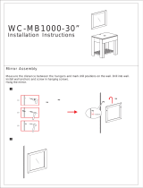
MOUNTING THE HUMIDIFIER
Mounting the humidifier on the wall
When mounting on a wood stud wall (studs 16” [406 mm] on center), locate studs and position lag bolts in place so that each of
the bolts centers on a stud. Mark hole locations and predrill ¼” (6 mm) diameter pilot holes. Secure cabinet to wall with lag bolts
provided.
When mounting on a metal stud wall, locate the studs (16” [406 mm] on center) and drill a 3/8” (10 mm) hole through the studs
and wall. Push a 3/8” (10 mm) bolt through the wall, studs, and a backing plate on the backside of the wall and secure with a nut
and washer.
If 16” (406 mm) on-center studs are not available, mount spanner boards on the wall, spanning two studs. If two horizontal boards
are used, locate one at the top of the cabinet for the lag bolts and the other board located 3” (76 mm) on center from the bottom
of the cabinet.
For hollow block or poured concrete wall mounting, mark holes 16” apart. Drill appropriate pilot holes for two 3/8” (10 mm) toggle
bolts or two 3/8” (10 mm) machine bolt lead anchors. Secure cabinet in place.
When suspending the unit from ceiling or roof structural members
Required Parts:
2 Brackets, P/N 4593
4 Bolts, 1/4 - 20, 3/4 long , plated.
4 Nylon insert nuts, 1/4 - 20
8 Flat Washers, 1/4 -20, plated (thin washers)
8 Washers, 1/4 -20, plated
4 Threaded Rods, 3/8 - 16 (length depends on installation specifics. Not provided.)
Procedure:
1. Remove the shroud covering of the humidifier.
2. Insert the first bolt through the side slot farthest to the rear of the humidifier. Follow the “Fastener Sequence” listed below,
ensuring the bolt head is on the inside of the humidifier frame.
3. Repeat the “Fastener Sequence” for the humidifiers vertical side slot located toward the front.
NOTE: The metal of the frame will need to be flexed in order to insert the left front bolt.
4. Repeat steps 2 & 3 for the other side.
5. Use four lengths of 3/8 inch threaded rod to suspend the humidifier. Observe all applicable codes and standards.
Fastener Sequence:
Starting from the inside of the humidifier:
Bolt, flat washer, through the vertical slots on the side of the humidifier frame, 1/4-20 washer, 1/4-20 washer, Bracket
(use the small holes the same side as the slots), flat washer, Nylon insert nut.
Attach one end of the steam hose to the distribution tube and the other end to the humidifier. Secure with 1 1/2” hose clamps
at both ends. Ensure that a minimum pitch of 2”/ft. (15%) is maintained along length of hose. If pitch is not possible, it will be
necessary to install a tee fitting and p-trap. Refer to Figure 23 on page 26 for details. If the 10’ hose is not long enough to reach
from the humidifier to the distribution tube, use 1-1/2” copper tubing.
INSTALL STEAM HOSE
18

Below are field wiring connections:
•
Connect to line power.
Refer to the wiring diagram or the dataplate on the outside of the cabinet for wire sizing amperage.
• Connect to control signal wiring.
(from the Automatic Steam Humidifier Control or from signal by others). Mount the Automatic Steam Humidifier Control in the
return air duct as shown in the drawing on pages 14 and 15. See page 21 for wiring details. Also, refer to the Installation and
Operating Manual for the Automatic Steam Humidifier Control.
• Connect to the HVAC system blower.
To start the HVAC equipment blower when the humidifier receives a humidity demand signal, wire the NO, O, and NC control
terminals to the HVAC system as shown on the wiring diagram.
• Connect to a remote fault alarm (optional).
The humidifier may be field programed to send a fault alarm signal to a remote device instead of sending a signal to start the
HVAC system blower. To enable this function, set slide switch S2 position 9 to On and provide wiring to control terminals NO,
O, and NC.
• Connect to the duct airflow proving switch wiring.
The airflow proving switch is a safety device that will prevent the humidifier from producing steam when there is no airflow
present in the HVAC system. See page 23 for details.
• Connect to the duct high humidity limit switch wiring.
(a recommended optional device). Locate the duct high humidity limit switch the correct distance downstream of the
distribution tube. See Figure 10 on page 14 and Figure 11 on page 15 for more location guidelines.
IMPORTANT: Installation of a duct high humidity limit switch is highly recommended.
CAUTION
Adding alternate conduit connections should not be necessary; however, when making holes and knockouts in the
humidifier cabinet, protect all internal components from debris and vacuum out cabinet when finished. Failure to comply
with this warning can damage sensitive electronic components and void the Aprilaire warranty.
FIELD WIRING
Humidifier field wiring
All wiring must be in accordance with all governing codes and with the humidifier wiring diagram. Wiring diagrams are on pages
9 and 10 in this manual and the wiring diagram for your humidifier model is located inside the removable shroud. Power supply
wiring must be rated for 221°F (105°C). The maximum ambient temperature is 80°F (27°C).
Field wiring connections and requirements
• Conduit knockouts are provided on the top of the cabinet. Control wiring knockouts are on the back right; power wiring
knockouts are on the back left.
• Control wiring and power wiring must be run in dedicated or separate earthed metal conduit, cable trays, or trunking.
• Separate the line voltage wiring from low voltage control circuit wiring when routing electrical wiring inside the
humidifier cabinet.
• Do not use chassis or safety grounds as current-carrying commons. Never use a safety ground as a conductor or neutral to
return circuit current.
19

OM-4007
Fused
disconnect
Power
supply
FIGURE 14 – Line Power Wiring Requirements
WARNING
240 volts may cause serious injury or death from electrical shock. Shut off power at main breaker before
installing supply wiring for humidifier.
LINE POWER
The humidifier is designed for 240 VAC, single phase, 50/60 Hz input
power. The Model 1150 requires a 25 amp (minimum) breaker while
the Model 1160 requires a 45 amp (minimum) breaker. Install a fused
quick disconnect box nearby the humidifier for easy access during
maintenance of humidifier. See Figure 14.
208 VAC single-phase, 50/60 Hz input power may also be used.
Note that when using 208 VAC the steam capacity of each unit will
be reduced by approximately 25% compared to rated capacity at
240 VAC.
Line power grounding requirements
The ground connection must be made with solid metal to metal
connections. The ground must be a good radio frequency earth.
Ground wire should be the same size as power wiring.
Proper control wiring prevents electrical noise
.
Electrical noise can produce undesirable effects on electronic
control circuits, which affects controllability. Electrical noise
is generated by electrical equipment such as inductive
loads, electric motors, solenoid coils, welding machinery, or
fluorescent light circuits. The electrical noise or interference
generated from these sources (and the effect on controllers)
is difficult to define, but the most common symptoms are
erratic control or intermittent operational problems.
IMPORTANT
• For maximum electromagnetic compatibility effectiveness,
wire all humidity, high limit, and airflow controls using
multicolored shielded plenum-rated cable with a ground
wire for the shield. Connect the ground wire to the
C terminal on the field wiring terminal block in the
humidifier. See Figure 15. Use wire less than 2” (50 mm)
in length for the shielded cable ground wire.
• Do not ground shield at the device end.
C terminal
FIGURE 15 – Shielded Cable Wire Connection to C Terminal
CONTROL WIRING
OM-4015
WARNING
Failure to properly ground unit may result in property damage due to fire, or serious injury or death from
electrical shock.
20
/