
XT
Electrode Steam Humidifier
Installation, Operation,
and Maintenance Manual

Page ii • DRI-STEEM XT Electrode Steam Humidifier Installation, Operation, and Maintenance Manual
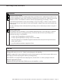
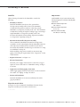
Warnings and cautions
Warnings and cautions
WARNING
Indicates a hazardous situation that could result in death or
serious injury if instructions are not followed.
CAUTION
Indicates a hazardous situation that could result in damage to
or destruction of property if instructions are not followed.
mc_051508_1145
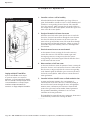
WARNING
Attention installer
Read this manual before installing, and leave this manual with product owner. This product must be installed by
qualified HVAC and electrical contractors and in compliance with local, state, federal, and governing codes. Improper
installation can cause property damage, severe personal injury, or death as a result of electric shock, burns, or fire.
DRI-STEEM
®
technical support: 800-328-4447
Read all warnings and instructions
Read this manual before performing service or maintenance procedures on any part of the system. Failure to follow all
warnings and instructions could produce the hazardous situations described, resulting in property damage, personal
injury, or death.
Failure to follow the instructions in this manual can cause moisture to accumulate, which can cause bacteria and mold
growth or dripping water into building spaces. Dripping water can cause property damage; bacteria and mold growth
can cause illness.
mc_011909_1215
Hot surfaces and hot water
This steam humidification system has extremely hot surfaces. Water in steam cylinders, steam pipes, and dispersion
assemblies can be as hot as 212 °F (100 °C). Discharged steam is not visible. Contact with hot surfaces, discharged
hot water, or air into which steam has been discharged can cause severe personal injury. To avoid severe burns,
follow the cool-down procedure in this manual before performing service or maintenance procedures on any part of
the system.

DRI-STEEM XT Electrode Steam Humidifier Installation, Operation, and Maintenance Manual • Page iii
Warnings and cautions
CAUTION
Hot discharge water
Discharge water can be as hot as 212 °F (100 °C) and can damage the drain plumbing.
Humidifiers equipped with a water tempering device need fresh make-up water in order to function properly. Make sure the
water supply to the water tempering device remains open during draining.
If the humidifier is not equipped with a water tempering device, allow the tank to cool before opening the drain valve.
Excessive supply water pressure
Supply water pressure greater than 80 psi (550 kPa) can cause the humidifier to overflow.
WARNING
Disconnect electrical power
Disconnect electrical power before installing supply wiring or performing service or maintenance procedures on any
part of the humidification system. Failure to disconnect electrical power could result in fire, electrical shock, and other
hazardous conditions. These hazardous conditions could cause property damage, personal injury, or death.
Contact with energized circuits can cause property damage, severe personal injury, or death as a result of electrical
shock or fire. Do not open control cabinet or remove heater terminal or subpanel access panels until electrical power
is disconnected.
Follow the shutdown procedure in this manual before performing service or maintenance procedures on any part of
the system.
mc_011909_1135
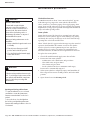
Electrical shock hazard
If the humidifier starts up responding to a call for humidity during maintenance, severe bodily injury or death from
electrical shock could occur. To prevent such start-up, follow the procedure below before performing service or
maintenance procedures on this humidifier:
1. Use Vapor-logic
®
4 keypad/display to drain the cylinder.
2. Use Vapor-logic
®
4 keypad/display to change control mode to Standby.
3. Shut off all electrical power to humidifier using field-installed fused disconnect, and lock all power disconnect
switches in OFF position.
4. Close field-installed manual water supply shut-off valve.
mc_050808_1540

Page iv • DRI-STEEM XT Electrode Steam Humidifier Installation, Operation, and Maintenance Manual
Warnings and cautions ................................ ii
Overview
Product overview .......................................2
Specifications, capacities and weights .....................4
Fusing and line currents .................................5
Dimensions ............................................6
Installation
Selecting a location .....................................7
Mounting:
Keyhole locations and dimensions ......................8
Clearances ...........................................9
Opening and closing cabinet doors .....................10
Removing cabinet doors ..............................10
Removing steam cylinder .............................10
Wall mounting humidifier ............................10
Fill cup extension kit ...................................11
Steam cylinder .........................................12
Condensate return guidelines ............................12
Piping:
Supply water and drain ...............................13
XT models 5 through 100 ............................14
XT models 150 and 200 ..............................15
XT steam blowers ....................................16
Humidifier wiring .....................................19
Humidistat and transmitter placement
....................22
Dispersion:
Selecting the dispersion assembly location ..............23
Interconnecting piping requirements
Connecting to humidifier with steam hose ...........24
Connecting to humidifier with tubing or pipe ........25
Drip tee installation ..................................28
Single dispersion tube ................................29
Rapid-sorb
Pitch requirements ................................33
Header outside of duct, horizontal airflow ...........34
Header inside of duct, horizontal airflow ............36
Steam supply connections to Rapid-sorb header ......38
Condensate drain connections to Rapid-sorb header . . 38
Ultra-sorb Model LV or LH ...........................38
XT steam blowers
Mounting XTSB on top of humidifier ...............41
Wiring top-mounted XTSB ........................41
Wall mounting XTSB .............................42
Wiring wall-mounted XTSB .......................43
Installing base plate ...............................43
Piping condensate to XT humidifier fill cup cap ......43
Piping condensate to drain .........................43
Table of contents

DRI-STEEM XT Electrode Steam Humidifier Installation, Operation, and Maintenance Manual • Page 1
Table of contents
Controller
The
Vapor-logic
®
4 Installation and Operation
Manual
ships with XT humidifiers. It is
a comprehensive manual. Refer to it for
information about the keypad/display and Web
interface, and for troubleshooting information.
Download DRI-STEEM literature
DRI-STEEM product manuals can be
downloaded, printed, and ordered from our
web site: www.dristeem.com
Operation
Supply water considerations .............................44
Principle of operation ..................................46
Staging multiple XT humidifiers .........................46
Components ..........................................47
Start-up procedure .....................................48
Start-up checklist ......................................49
Maintenance
Scheduled maintenance ................................50
Steam cylinder .........................................50
Drain valve ............................................52
Troubleshooting ......................................53
DRI-STEEM Technical Support .........................53
Replacement parts:
XT humidifier models 5 through 100 ...................54
XT humidifier models 150 and 200 ....................56
Steam blowers XTSB-20 and XTSB-50 ..................58
Warranty ................................... Back cover

Page 2 • DRI-STEEM XT Electrode Steam Humidifier Installation, Operation, and Maintenance Manual
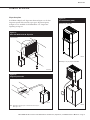
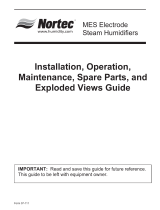
Product overview
Notes:
See Pages 14 and 15 for detailed installation
drawings.
Damage caused by chloride corrosion is not
covered by your DRI-STEEM warranty.
Supply water
XT electrode steam humidifiers use hard or softened supply water.
Water conductivity must be in the range of 125 to 1250 μS/cm
(roughly equivalent to 3.4 to 36.3 grains per gallon). See “Supply
water considerations” on Page 44.
Demineralized, deionized, and reverse-osmosis water cannot be
used, because they are not conductive enough for electrode steam
humidifiers.
Heated supply water cannot be used, because unheated supply water
is required for drain water tempering.
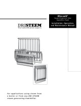
Overview
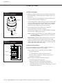
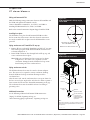
Figure 2-2:
XT humidifier installation overview
OM-7586
Electrical
knockouts
Wall mounting
keyholes
(behind cabinet)
Steam hose, tubing,
or pipe to duct dispersion
or XT steam blower (XTSB)
Duct
Rapid-sorb
dispersion panel
Replaceable steam cylinder
Condensate to drain
Water fill line connection
(under cabinet)
Vapor-logic4
keypad/display
Figure 2-1:
Vapor-logic controller interfaces
Keypad/display
Web interface
Softkeys
for direct
menu
access
Navigation
buttons
for item
selection
System
alarms
Cylinder
status
Set point
System
messages
Mode
Room RH
Output
Fill cup extension kit
required for some
models and applications
(see Page 11)

DRI-STEEM XT Electrode Steam Humidifier Installation, Operation, and Maintenance Manual • Page 3
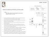
Product overview
Dispersion options
In addition to Rapid-sorb dispersion shown in Figure 2-2, the duct
dispersion options below and the open space dispersion options
in Figure 3-3 are available for XT humidifiers. See “Dispersion”
beginning on Page 23.
Overview
Figure 3-1:
Ultra-sorb Model LV or LH dispersion
OM-7587X
Figure 3-2:
Single dispersion tube
OM-7585
Note: Models XT-30 and larger require condensate drain when using 1½“
(DN40) pipe or hose.
Figure 3-3:
XT steam blowers (XTSB)
Mounted on top of humidifier
Mounted up to 10' (3 m) away from humidifier
OM-7596
OM-7597
Model LV shown

Page 4 • DRI-STEEM XT Electrode Steam Humidifier Installation, Operation, and Maintenance Manual
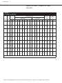
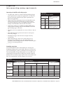
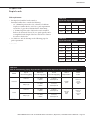
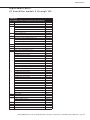
Specifications, capacities and
weights
Table 4-1:
XT humidifier specifications
XT
model kW
Max. steam
capacity
Current draw (amps)
Shipping
weight
Max.
operating
weight
Single-phase Three-phase
lbs/hr kg/h 120V 208V 230V 240V 277V 480V 600V 208V 240V 400V 480V 600V lbs kg lbs kg
5 1.7 5 2.3 14.2 8.2 7.4 7.1 — — — — — — — — 47.2 21.4 46.3 21.0
10 3.4 10 4.5 — 16.3 14.8 14.2 12.3 7.1 5.7 9.4 8.2 4.9 4.1 3.3 47.2 21.4 46.3 21.0
20 6.7 20 9.1 — 32.2 29.1 27.9 24.2 14.0 11.2 18.6 16.1 9.7 8.1 6.4 48.1 21.8 54.0 24.5
30 10.1 30 13.6 — ——————28.0 24.3 14.6 12.1 9.7 62.2 28.2 87.5 39.7
50 16.8 50 22.7 — ——————46.6 40.4 24.2 20.2 16.2 62.2 28.2 87.5 39.7
75 25.1 75 34.0 — ————————36.2 30.2 24.2 75.2 34.1 124.3 56.4
100 33.5 100 45.4 — ————————48.4 40.3 32.2 75.2 34.1 124.3 56.4
150 50.3 150 68.1 — ————————72.6 60.5 48.4 129.2 58.6 242.9 110.2
200 67.0 200 90.8 — ————————96.7 80.6 64.5 129.2 58.6 242.9 110.2
Note: For circuit protection requirements, see Table 5-1.
mc_090110_1020
Overview

DRI-STEEM XT Electrode Steam Humidifier Installation, Operation, and Maintenance Manual • Page 5
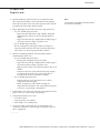
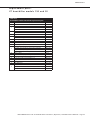
Fusing and line currents
Table 5-1:
Recommended fusing and line currents for XT humidifiers
Model Phase Volts
Line amps
kW
Recommended
fusing amps
L1 L2 L3
XT-5 1
120 14.2 14.2 — 1.7 25
208 8.2 8.2 — 1.7 15
230 7.4 7.4 — 1.7 13
240 7.1 7.1 — 1.7 15
XT-10
1
208 16.3 16.3 — 3.4 25
230 14.8 14.8 — 3.4 25
240 14.2 14.2 — 3.4 25
277 12.3 12.3 — 3.4 20
480 7.1 7.1 — 3.4 15
600 5.7 5.7 — 3.4 10
3
208 9.4 9.4 9.4 3.4 15
240 8.2 8.2 8.2 3.4 15
400 4.9 4.9 4.9 3.4 13
480 4.1 4.1 4.1 3.4 10
600 3.3 3.3 3.3 3.4 10
XT-20
1
208 32.2 32.2 — 6.7 50
230 29.1 29.1 — 6.7 50
240 27.9 27.9 — 6.7 45
277 24.2 24.2 — 6.7 40
480 14.0 14.0 — 6.7 25
600 11.2 11.2 — 6.7 20
3
208 18.6 18.6 18.6 6.7 30
240 16.1 16.1 16.1 6.7 25
400 9.7 9.7 9.7 6.7 16
480 8.1 8.1 8.1 6.7 15
600 6.4 6.4 6.4 6.7 10
XT-30 3
208 28.0 28.0 28.0 10.1 45
240 24.3 24.3 24.3 10.1 40
400 14.6 14.6 14.6 10.1 25
480 12.1 12.1 12.1 10.1 20
600 9.7 9.7 9.7 10.1 15
XT-50 3
208 46.6 46.6 46.6 16.8 70
240 40.4 40.4 40.4 16.8 70
400 24.2 24.2 24.2 16.8 40
480 20.2 20.2 20.2 16.8 35
600 16.2 16.2 16.2 16.8 25
XT-75 3
400 36.2 36.2 36.2 25.1 63
480 30.2 30.2 30.2 25.1 50
600 24.2 24.2 24.2 25.1 40
XT-100 3
400 48.4 48.4 48.4 33.5 80
480 40.3 40.3 40.3 33.5 70
600 32.2 32.2 32.2 33.5 50
XT-150 3
400 72.6 72.6 72.6 50.3 125
480 60.5 60.5 60.5 50.3 100
600 48.4 48.4 48.4 50.3 80
XT-200 3
400 96.7 96.7 96.7 67.0 150
480 80.6 80.6 80.6 67.0 125
600 64.5 64.5 64.5 67.0 100
mc_110110_1457
Overview

Page 6 • DRI-STEEM XT Electrode Steam Humidifier Installation, Operation, and Maintenance Manual
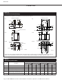
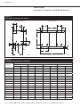
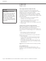
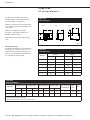
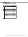
Dimensions
Overview
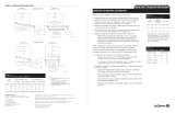
Table 6-1:
Dimensions by model number
Dimension Description
XT models
5, 10, and 20 30 and 50 75 and 100 150 and 200
inches mm inches mm inches mm inches mm
A Cabinet width 16.06 408 19.21 488 21.46 545 39.76 1010
B Cabinet height 23.94 608 25.83 656 27.99 711 27.99 711
C Cabinet depth including doors 12.05 306 14.09 358 16.89 429 16.97 431
D Cabinet depth not including doors 10.00 254 11.80 300 14.40 184 14.40 184
E Cabinet left edge to steam/drain outlet centers 4.61 117 6.22 158 7.20 183 7.24 184
F Cabinet back edge to steam/drain outlet centers 6.14 156 6.18 157 7.24 184 7.24 184
mc_091010_0920
mc_090710_0946
* Fill cup extension kit is required for XT humidifier models 75 through 200 (ships loose with these models), for all XT humidifiers using Rapid-sorb or Ultra-sorb
dispersion, and for all XT humidifiers with more than 20' (6 m) maximum developed length of tubing/pipe from humidifier to dispersion assembly.
Figure 6-1:
XT humidifier dimensional drawings
Labeled dimensions: inches (millimeters). See mounting dimensions and electrical knockouts in Figure 8-1.
Front
Top
Bottom
XT models 5 through 100
OM-7593
E
C
F
2.00 (51)
Dispersion outlet
Top
Bottom
Front
Drain outlet
Electrical knockouts
Water fill line
connection
F
2.38
(60.3)
1.38 (34.9)
E
3.05 (77.5)
2.05 (52.1)
4.05 (102.9)
A
B
OM-7581
2.05
(52.1)
4.1
(102.9)
3.05
(77.5)
10
(254)
A
32.2 (818)
E
F
C
B
E
F
XT models 150 and 200
2.00
(51)
26.8 (681)
1.85 (47)
1.85 (47)
10 (254)
2.36
(60)
6.1 (155)
1.38 (35)
17.4 (442)
22.09
(561)
32.2 (818)
26.38 (670)
Dispersion outlets
Drain outlets
Fill cup extension kit*
D
D
Water fill line
connection
Fill cup extension kits*

DRI-STEEM XT Electrode Steam Humidifier Installation, Operation, and Maintenance Manual • Page 7
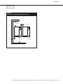
Installation
Selecting a location
Important:
Install humidifier only in locations that meet the
following temperature and relative humidity (RH)
requirements:
Maximum ambient temperature:
104 °F (40 °C)
Minimum ambient temperature:
41 °F (5 °C)
Maximum ambient humidity:
80% RH (non-condensing)
Humidifier
When selecting a location for the humidifier, consider the
following:
• Proximity to the duct
Install the humidifier near the air duct system where
the dispersion assembly will be located. The maximum
recommended length for steam hose connecting a single
humidifier to a dispersion assembly is 10' (3 m). The maximum
recommended developed length for tubing or pipe connecting a
single humidifier to a dispersion assembly is 20' (6 m).
For more information about installing dispersion assemblies,
see “Dispersion” beginning on Page 23.
• Elevation of the installed dispersion assembly
The recommended installation location for the dispersion
assembly is at an elevation higher than the humidifier. However,
if the dispersion assembly must be installed at an elevation
lower than the humidifier, install a drip tee and drain. See “Drip
tee installation” on Page 28.
Before installing a dispersion assembly or interconnecting
piping, review all pitch requirements in the “Dispersion” section
of this manual.
• Required clearances (see Figure 9-1)
• Electrical connections
Electrical power supply connections are at the lower or upper
right rear corner of the unit. See “Humidifier wiring” on Pages
19 and 20.
• Supply water and drain piping connections
Water supply piping and drain connections are at the bottom of
the cabinet. See “Piping” on Pages 14 and 15.
• Exterior wall insulation
Install the humidifier on an exterior wall only if the wall is
properly insulated.
Dispersion control devices
See Figure 22-1 for recommended installation locations for the
dispersion assembly and associated control devices.
mc_062810_0928-NA

Page 8 • DRI-STEEM XT Electrode Steam Humidifier Installation, Operation, and Maintenance Manual
Installation
Mounting:
Keyhole locations and dimensions
Figure 8-1:
XT humidifier mounting keyhole locations
B
E
F
C
A
D
G
OM-7594
OM-7582
A
B
C
D
E
Ø O
XT models 5 through 100 XT models 150 and 200
A
G
J
K
Ø N
I
Ø N
J
K
L
M
F
I
H
P
mc_091010_0923
Table 8-1:
XT humidifier mounting keyhole dimensions
Dimension
XT models
5, 10, and 20 30 and 50 75 and 100 150 and 200
inches mm inches mm inches mm inches mm
A 5.00 127 8.15 207 9.62 244 8.00 203
B 16.52 420 18.12 460 20.24 514 19.27 489
C 3.60 91 3.60 91 4.39 112 4.95 126
D — — — — 6.39 162 2.54 65
E 0.97 25 1.33 34 1.33 34 2.73 69
F 6.40 163 6.40 163 6.40 163 6.19 157
G — — — — 0.80 20 16.00 406
H 1.88 48 1.88 48 1.88 48 — —
I 1.63 41 1.63 41 1.63 41 1.70 43
J 2.06 52 2.06 52 2.11 54 13.10 333
K 4.06 103 4.06 103 4.11 104 38.09 967
L 7.89 200 9.47 241 10.59 269 — —
M 14.43 367 17.44 443 18.65 474 — —
N 1.51 38 1.51 38 1.51 38 1.00 25
O 1.00 25 1.00 25 1.00 25 — —
P 7.12 181 7.12 181 7.19 183 — —
mc_091010_0925

DRI-STEEM XT Electrode Steam Humidifier Installation, Operation, and Maintenance Manual • Page 9
Installation
Mounting:
Clearances
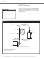
Figure 9-1:
XT humidifier recommended minimum clearances
OM-7583
16” (400 mm)
15” (380 mm)
3” (76 mm) between units
3”
(76 mm)
36” (914 mm)
front clearance
mc_091010_0922

Page 10 • DRI-STEEM XT Electrode Steam Humidifier Installation, Operation, and Maintenance Manual
Unpack the humidifier from the shipping carton, and remove the
cabinet doors and steam cylinder.
Removing cabinet doors
XT humidifier and XTSB doors have lift-off hinges for easy removal
of open doors. The doors are captivated when closed but should be
removed when open. An upward bump could damage the door if it
jumps the hinges and falls.
Removing steam cylinder
Make sure the cylinder is empty and cooled before removing it.
1. Disconnect electrode and high water sensor connectors from
steam cylinder.
2. Place hands palms-down below cylinder on both sides of drain
outlet.
3. Press up against bottom of cylinder with backs of hands while
pressing down against cabinet floor with fingers.
4. Raise cylinder until drain outlet clears drain valve body, and
remove cylinder from cabinet.
Wall mounting humidifier
Follow the instructions below for your model and wall type, and
mount the humidifier level and plumb. See Figures 14-1 and 15-1.
• Wood studs 16" (406 mm) on center, XT models 75 through 200:
Mark hole locations at centers of studs, and predrill ¼" (6 mm)
diameter pilot holes. Secure humidifier to wall with lag bolts
(provided).
• Metal studs 16" (406 mm) on center, XT models 75 through 200:
Mark hole locations at centers of studs. Using a drill bit just large
enough to push a 3/8" (10 mm) bolt through, drill through studs
and wall, and through a backing plate on other side of wall. Push
bolts through wall, studs, and backing plate. Secure humidifier to
wall with bolts, and secure backing plate with washers and nuts.
• XT models 5 through 50, and XT models 75 through 200 if
16"-on-center (406 mm) studs are not available:
Mount spanner boards on wall, spanning at least two studs.
Position one board at top of cabinet (for the lag bolts), and the
other board at bottom of cabinet. Secure humidifier to spanner
boards with lag bolts.
• Hollow block or poured concrete wall, any XT model:
Mark hole locations, and drill appropriate pilot holes for two 3/8"
(10 mm) toggle bolts or two 3/8" (10 mm) machine bolt lead
anchors. Secure humidifier in place with bolts and anchors.
Installation
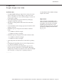
Opening and closing cabinet doors
To open the cabinet doors, use a slotted
screwdriver to rotate the quarter-turn
fastener counterclockwise so the slot is
vertical.
To close the doors, close the right then
the left door, and push the quarter-turn
fastener while turning clockwise so the slot
is horizontal.
Mounting
WARNING
Mounting hazard
Mount humidifier per the instructions
in this manual and to a structurally
stable surface. Improper mounting of
the humidifier can cause it to fall or tip,
resulting in severe personal injury or
death.
mc_060110_1540

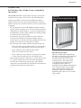
DRI-STEEM XT Electrode Steam Humidifier Installation, Operation, and Maintenance Manual • Page 11
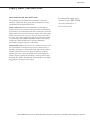
Figure 11-1:
Fill cup extension kit
A fill cup extension kit (Figure 11-1) is required for any of the
following:
• XT humidifier models 75 through 200 (fill cup extension kit
ships loose with these models)
• All XT humidifiers using Ultra-sorb or Rapid-sorb dispersion
• All XT humidifiers with more than 20' (6 m) maximum
developed length of tubing/pipe from humidifier to dispersion
assembly
mc_110110_1455
Installation
Fill cup extension kit
OM-7588
Fill valve adapter
Overflow elbow
Drain cup plate
Supply water hose (A)
Cylinder fill hose (B)
Overflow hose (C)
Fill cup
(see inset below)
OM-7629
Cylinder fill (B)
Supply water (A)
Overflow (C)
Fill cup
Fill connection
mc_102810_1430
Removing existing fill cup: XT models 5 through 50
If installing a fill cup extension kit for XT models 5 through 50, first
remove the existing fill cup as follows:
1. Remove steam cylinder from XT cabinet (if not already out).
See “Removing steam cylinder” on Page 10.
2. Expand spring clamps and slide them up cylinder fill hose and
supply water hose, and disconnect hoses from fill connection
and fill valve adapter.
3. Disconnect overflow hose from overflow elbow.
4. Fill cup is press fit into top of XT cabinet. Rock fill cup back
and forth while pushing up until it comes out, then remove fill
cup and hoses.
Installing fill cup extension kit: all XT models
1. Remove steam cylinder(s) from XT cabinet (if not already out).
See “Removing steam cylinder” on Page 10.
2. Route fill cup extension kit hoses into cabinet through fill cup
hole, and fasten extension bracket as shown with two screws
provided.
3. Cut supply water hose (small-diameter hose) (A) to length so it
can attach to fill valve adapter without kinking.
4. Expand spring clamp and slide it onto supply water hose (A)
far enough so it will not interfere, then push hose onto fill valve
adapter. Expand and slide spring clamp into place.
5. Cut cylinder fill hose (bottom, center hose) (B) to length so it
can attach to fill connection without kinking.
6. Expand spring clamp and slide it onto cylinder fill hose (B)
far enough so it will not interfere, then push hose onto fill
connection. Expand and slide spring clamp into place.
7. Cut overflow hose (C) to length so it can attach to overflow
elbow without kinking.
8. Push overflow hose onto overflow elbow. No spring clamp is
required on this connection.

Page 12 • DRI-STEEM XT Electrode Steam Humidifier Installation, Operation, and Maintenance Manual
Figure 12-2:
Steam cylinder installation
OM-7623X
Drain valve body
Cylinder guide
Installing steam cylinder
1. Make sure strainer is pressed into steam cylinder drain outlet
and strainer flange is flush with bottom of cylinder outlet. See
Figure 12-1.
2. Use water to lubricate drain outlet on bottom of cylinder and
o-ring in drain valve body. See Figure 12-2.
3. With Warning label on cylinder facing you, lower cylinder drain
outlet into drain valve body, and rotate cylinder so side tabs line
up with cylinder guides inside cabinet. Push down on cylinder
until drain outlet is fully seated in drain valve body.
4. Connect high water sensor (yellow) wire to single pin
surrounded by plastic shoulder on cylinder.
5. Connect electrode plugs to pins on cylinder. Make sure all plugs
fit snugly and are fully engaged on pins.
Note: If cylinder plugs becomes loose, obtain replacement plugs
from DRI-STEEM. See “Replacement parts" on Pages 55
and 57 for part numbers.
Important: Cylinders with six electrodes have color-coded
dots on the cylinder and color bands on the electrode plugs.
When connecting the plugs, match the band colors on the plugs
with the dot colors on the cylinder. Refer to the wiring diagram
shipped with the humidifier if necessary.
Condensate return guidelines
To prevent overfilling the steam cylinder, follow the guidelines
below when returning condensate to the cylinder:
• When condensate can be returned to the steam cylinder:
– Single tube dispersion
– Less than 20 lbs/hr (9.1 kg/h) of steam production
– 20' (6 m) or less of steam hose, tubing, or pipe between
humidifier and dispersion
• When condensate should be wasted to the drain:
– Ultra-sorb or Rapid-sorb dispersion
– Single tube dispersion with condensate drain and:
- 20 lbs/hr (9.1 kg/h) or of more steam production, or
- More than 20' (6 m) of steam hose, tubing, or pipe between
humidifier and dispersion
Installation
Steam cylinder
Figure 12-1:
Steam cylinder installation
OM-7623X
Strainer
High water
sensor pin

DRI-STEEM XT Electrode Steam Humidifier Installation, Operation, and Maintenance Manual • Page 13
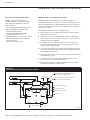
Installation
Piping:
Supply water and drain
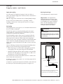
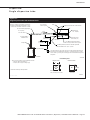
Figure 13-1:
Drain piping detail
OM-7589
* Hose clamp and black rubber hose ship with each humidifier;
they can also be ordered from DRI-STEEM. See the
replacement parts section of this manual for part numbers.
Important: Thoroughly flush the
supply water piping to remove pipe residue
and stagnant water before connecting piping
to the humidifier. Pipe residue and stagnant
water in the water supply piping can cause
foaming, preventing the humidifier from
reaching the required steam capacity.
WARNING
Hot drain pipes
Drain piping surface may be hot. Touching
or contact with hot pipe may cause severe
personal injury.
Piping drawings:
See the piping drawings on Pages 14 and 15.
Black rubber hose*
¾" (DN20) I.D.
Open drain
1" (25 mm) air gap
Pitch 1/8”/ft (1%) towards drain
Hose clamp*
To drain
Supply water piping
Use only copper for supply water piping; do not use rubber or
plastic. The standard supply water connection before the fill valve is
a 1/4" FIP strainer.
Note: The supply water connection size is 3/8"BSP [DN10] in Europe.
In cases where water hammer may be a possibility, consider
installing a shock arrestor. Water pressure must be 25 to 80 psi
(175 to 550 kPa).
Drain piping
Drain piping must be code-approved, ¾" (DN 20) ID material rated
for 212 °F (100°C) minimum.
The XT drain cup has an integral grounding plate and requires
a field-installed 1" (25 mm) air gap to a drain funnel to prevent
conduction of electricity in the drain line.
The XT humidifier tempers drain water by opening the fill valve
whenever the drain valve is energized, which automatically cools
drain water before it enters the drain. Drain water tempering is
intended to keep water entering the drain line no hotter than 140°F
(60°C). However, manually energizing the drain valve when the
supply water is shut off can allow 212 °F (100 °C) water to enter the
drain line.
Observe following precautions when selecting and installing drain
piping to ensure personal safety and material integrity:
• When using copper or other metallic drain piping, ground the
drain piping to the earth ground lug in the XT humidifier.
• Chlorinated polyvinyl chloride (CPVC) piping is a non-metallic
alternative for drain piping. It is rated up to 212°F (100°C) for
intermittent-use, low-pressure applications.
The connection size for the steam cylinder drain is 1" (DN25) hose.
Do not reduce this connection size.
If drainage by gravity is not possible, use a reservoir pump rated for
212 °F (100 °C) water.
A drain hose is provided to function as the flexible connection from
the drain cup to the field-installed open drain. See Figure 13-1.
mc_102810_1415

Page 14 • DRI-STEEM XT Electrode Steam Humidifier Installation, Operation, and Maintenance Manual
Installation
Piping:
XT models 5 through 100
Figure 14-1:
XT humidifier field piping overview, models 5 through 100
Dashed lines indicate provided by installer.
Steam hose; may also use tubing or pipe.
See Table 24-1 for maximum piping lengths.
Tubing or pipe must be grounded.
3/8” (DN10) copper water supply line; water pressure must be 25 to 80 psi
(175 to 550 kPa).
Install plumb
3/4” (DN20) drain piping. If piping run
is over 10’ (3 m), increase pipe to 1¼”
(DN32).
Supply valve, by installer
Hose and clamp
Inlet strainer, by installer
Pitch*
OM-7584
Shock arrester (by installer)
recommended to reduce water hammer
Plumb spill funnel to floor drain.
Floor drain
Open drain required directly below humidifier drain to prevent
downstream drain line blockage from causing water to back up
into cylinder. Refer to governing codes for drain pipe size and
maximum discharge water temperature.
1” (25 mm) air gap required to isolate drain
water from cylinder water. Locate air gap
only in spaces with adequate temperature
and air movement to absorb flash steam, or
condensing on nearby surfaces could occur.
Metallic water supply line
* Pitch 1/8”/ft (1%)
toward drain
mc_090210_0845
Fill valve with 1/4” FIP strainer
(3/8"BSP [DN10] in Europe)

DRI-STEEM XT Electrode Steam Humidifier Installation, Operation, and Maintenance Manual • Page 15
Installation
Piping:
XT models 150 and 200
Figure 15-1:
XT humidifier field piping overview, models 150 and 200
OM-7595
Install
plumb
3/4” (DN20) drain piping up to second drain connection
Supply valve, by installer
Hose and clamp
Inlet strainer, by installer
Dashed lines indicate provided by installer.
Pitch*
Shock arrester
(by installer)
recommended
to reduce water
hammer
Floor drain
Open drains required directly below humidifier
drains to prevent downstream drain line blockage
from causing water to back up into cylinder. Refer
to governing codes for drain pipe size and maximum
discharge water temperature.
Metallic water
supply line
3/8” (DN10) copper water supply line; water pressure must be 25 to 80 psi (175 to 550 kPa).
mc_090210_0847
Steam hose; may also use tubing or pipe.
See Table 24-1 for maximum piping lengths.
Tubing or pipe must be grounded.
* Pitch 1/8”/ft (1%) toward drain
Fill valve with 1/4”
FIP strainer
(3/8"BSP [DN10]
in Europe)
1¼” (DN32) drain piping after second drain
connection
1” (25 mm) air gap required to isolate drain water
from cylinder water. Locate air gap only in spaces
with adequate temperature and air movement
to absorb flash steam, or condensing on nearby
surfaces could occur.

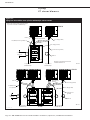
Page 16 • DRI-STEEM XT Electrode Steam Humidifier Installation, Operation, and Maintenance Manual
Installation
Piping:
XT steam blowers
o
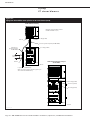
Figure 16-1:
Piping from XT humidifier steam cylinders to XT steam blowers (XTSB)
XTSB mounted remotely
XTSB mounted directly on top of
XT humidifier
Hose clamp (provided)
Hose clamp (provided)
Steam hose (provided)
OM-7603
Plastic tie
Condensate hose
(purchased separately
from DRI-STEEM)
Plastic tie
Hose clamp (provided)
Steam hose (purchased separately from DRI-STEEM)
Hose clamp (provided)
To open drain or humidifier fill cup
Water seal is required, whether condensate is piped to open
drain or returned to humidifier fill cup.
OM-7602
7” (178 mm)
water seal
Maximum recommended distance between
humidifier and XTSB is 10’ (3 m).
mc_091010_0939
Page is loading ...
Page is loading ...
Page is loading ...
Page is loading ...
Page is loading ...
Page is loading ...
Page is loading ...
Page is loading ...
Page is loading ...
Page is loading ...
Page is loading ...
Page is loading ...
Page is loading ...
Page is loading ...
Page is loading ...
Page is loading ...
Page is loading ...
Page is loading ...
Page is loading ...
Page is loading ...
Page is loading ...
Page is loading ...
Page is loading ...
Page is loading ...
Page is loading ...
Page is loading ...
Page is loading ...
Page is loading ...
Page is loading ...
Page is loading ...
Page is loading ...
Page is loading ...
Page is loading ...
Page is loading ...
Page is loading ...
Page is loading ...
Page is loading ...
Page is loading ...
Page is loading ...
Page is loading ...
Page is loading ...
Page is loading ...
Page is loading ...
Page is loading ...
-
 1
1
-
 2
2
-
 3
3
-
 4
4
-
 5
5
-
 6
6
-
 7
7
-
 8
8
-
 9
9
-
 10
10
-
 11
11
-
 12
12
-
 13
13
-
 14
14
-
 15
15
-
 16
16
-
 17
17
-
 18
18
-
 19
19
-
 20
20
-
 21
21
-
 22
22
-
 23
23
-
 24
24
-
 25
25
-
 26
26
-
 27
27
-
 28
28
-
 29
29
-
 30
30
-
 31
31
-
 32
32
-
 33
33
-
 34
34
-
 35
35
-
 36
36
-
 37
37
-
 38
38
-
 39
39
-
 40
40
-
 41
41
-
 42
42
-
 43
43
-
 44
44
-
 45
45
-
 46
46
-
 47
47
-
 48
48
-
 49
49
-
 50
50
-
 51
51
-
 52
52
-
 53
53
-
 54
54
-
 55
55
-
 56
56
-
 57
57
-
 58
58
-
 59
59
-
 60
60
-
 61
61
-
 62
62
-
 63
63
-
 64
64


Ask a question and I''ll find the answer in the document
Finding information in a document is now easier with AI
Related papers
-
DriSteem XT-150 Installation, Operation and Maintenance Manual
-
 DriSteem Ultra-sorb LV Installation, Operation and Maintenance Manual
-
 DriSteem Rapid-sorb Quick start guide
-
 DriSteem Ultra-sorb XV Installation, Operation and Maintenance Manual
-
 DriSteem Ultra-sorb LV Installation, Operation and Maintenance Manual
-
 DriSteem ultra-sorb MP Installation, Operation and Maintenance Manual
-
 DriSteem Vapor-Logic Installation guide
-
DriSteem VAPORMIST Installation, Operation and Maintenance Manual
-
-
 DriSteem Ultra-sorb XV Installation, Operation and Maintenance Manual


Other documents
-
Trane EHUMD800ASM00BA Steam Humidifier Owner's manual
-
Carrier HUMCRSTM3134 Owner's manual
-
Ginger USA 1139CR5/SN Installation guide
-
CAC / BDP HUMCRSTM Owner's manual
-
 Nortec MES Electrode Operating instructions
-
Vantec Stealth User manual
-
 Water Creation WO-0001-05 Installation guide
-
Condair 08 111 MES User manual
-
-
Aprilaire 800 Installation guide

