Page is loading ...

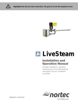
STEAM INJECTION
Humidifiers
Installation, Operation,
and Maintenance Manual
READ AND SAVE THESE INSTRUCTIONS
For use with steam boilers

ii
STEAM INJECTION INSTALLATION, OPERATION, AND MAINTENANCE MANUAL
Safety precautions
ATTENTION INSTALLER
Read this manual before installing.
Leave manual with product owner.
Where to find more information
On our website:
The following related documents can be
viewed, printed, or ordered from our
website, www.dristeem.com
In Dri-calc
®
Dri-calc is DriSteem’s free sizing and
selection software for calculating load,
determining non-wetting distance, and
selecting equipment. See Dri-calc on the
www.dristeem.com Tools page. Also in
Dri-calc:
A comprehensive library of Installation
Guide documents, including:
• Recommended placement within a duct
or air handler
• Recommended sensor placement
Or call us at 800-328-4447
Obtaining documents from our website or
from Dri-calc is the quickest way to view
our literature, or we will be happy to mail
literature to you.
WARNING
Indicates a hazardous situation that could result in death or serious
injury if instructions are not followed.
WARNING
Attention installer
Read this manual before installing, and leave this manual with
product owner. This product must be installed by qualified
HVAC and electrical contractors and in compliance with local,
state, federal, and governing codes. Improper installation can
cause property damage, severe personal injury, or death as a
result of electric shock, burns, or fire.
DriSteem
®
technical support: 800-328-4447
Read all warnings and instructions
Read this manual before performing service or maintenance
procedures on any part of the system. Failure to follow all
warnings and instructions could produce the hazardous
situations described, resulting in property damage, personal
injury, or death.
Failure to follow the instructions in this manual can cause
moisture to accumulate, which can cause bacteria and mold
growth or dripping water into building spaces. Dripping water
can cause property damage; bacteria and mold growth can
cause illness.
mc_011909_1215
Hot surfaces and hot water
Steam Injection humidifiers have extremely hot surfaces. Water
in steam pipes and dispersion assemblies can be as hot as
212 °F (100 °C). Discharged steam is not visible. Contact with
hot surfaces, discharged hot water, or air into which steam
has been discharged can cause severe personal injury. To
avoid severe burns, allow the system to cool before performing
service or maintenance procedures on any part of the system.

1
STEAM INJECTION INSTALLATION, OPERATION, AND MAINTENANCE MANUAL
Table of contents
ATTENTION INSTALLER
Read this manual before installing.
Leave manual with product owner.
DriSteem technical support
800-328-4447
WARNING
Hot surface hazard
Steam humidification systems have
extremely hot surfaces.
To avoid burns, allow humidifier, steam
pipes, and dispersion assemblies to
cool before touching any part of the
system.
mc_071411_0753
OVERVIEW.................................................................2
Introduction .............................................2
Available models .........................................3
Basic components ........................................4
Principle of operation ......................................5
Humidifier placement ......................................6
Sensor placement ........................................9
Pressurized steam piping guidelines ..........................10
Condensate drain piping and trapping ........................14
Temperature switches .....................................16
SINGLE-TUBE HUMIDIFIER ....................................................20
Configurations .........................................20
Assembly .............................................21
Installation ............................................22
Piping notes ...........................................23
Field piping ...........................................24
MULTIPLE-TUBE HUMIDIFIER ..................................................28
Field assembly .........................................28
Installation ............................................29
Piping notes ...........................................30
Field piping ...........................................31
MAXI-BANK HUMIDIFIER .................................................... 36
Maxi-bank option field assembly and installation .................36
Maxi-bank option piping notes ..............................39
Maxi-bank option field piping ...............................40
Assembly and installation ..................................45
MINI-BANK HUMIDIFIER ..................................................... 45
Field piping ...........................................47
AREA-TYPE HUMIDIFIER ..................................................... 48
Installation ............................................48
Field piping ...........................................49
Rise, spread, and throw dimensions ..........................50
Humidifier start-up and shut-down ............................51
OPERATION .............................................................. 51
Eliminating excess heat from steam jacketed humidifiers ............52
MAINTENANCE ........................................................... 54
Maintenance procedures ..................................54
Troubleshooting .........................................55
TROUBLESHOOTING........................................................ 55
REPLACEMENT PARTS ....................................................... 58
Single-tube and Multiple-tube humidifiers .......................58
Area-type humidifier .....................................60
Mini-bank humidifier .....................................61
WARRANTY .............................................................. 62

2
STEAM INJECTION INSTALLATION, OPERATION, AND MAINTENANCE MANUAL
Introduction
OVERVIEW
SUITABLE FOR A WIDE RANGE OF APPLICATIONS
Steam Injection humidifiers from DriSteem
®
use steam from an external source,
such as an in-house boiler or a district steam system. DriSteem’s Steam Injection
humidifiers are adaptable to virtually any size application, and a wide variety
of models accommodate a broad range of steam absorption requirements.
STEAM JACKETED DISPERSION TUBE MODELS FOR DUCTS AND AIR HANDLERS
Single-tube, Mini-bank
®
, and Multiple-tube humidifiers are designed for ducts
and air handlers, and capable of a wide range of guaranteed non-wetting
distances.
AREA-TYPE FOR OPEN SPACES
Area-type
™
Steam Injection humidifiers are designed for
open spaces such as warehouses and manufacturing spaces
that do not have a duct system. The steam discharged
from the humidifier is quietly dispersed by a fan without
introducing water droplets into the air.
Each Single-tube, Mini-bank
®
, and Multiple-tube
humidifier has the same basic components: a
stainless steel separator, a steam valve, and
one or more jacketed dispersion tubes.
For open spaces, boiler steam can be
dispersed by the fan of an Area-type model.
FIGURE 2-1:
STEAM INJECTION HUMIDIFIERS

3
STEAM INJECTION INSTALLATION, OPERATION, AND MAINTENANCE MANUAL
Available models
OVERVIEW
All Steam Injection humidifiers shown here,
except Area-type, are available with options
for applications requiring stainless steel steam
components.
SINGLE-TUBE HUMIDIFIER
• Suitable for small- to medium-capacity systems,
1.5 – 525 lbs/hr (0.7 – 238 kg/h)
• Moderate to long non-wetting distance
• Pre-assembled separator/tube assembly
mc_033111_0500
FIGURE 3-1: STEAM INJECTION HUMIDIFIER MODELS
AREA-TYPE HUMIDIFIER
• Suitable for medium-capacity systems, 1.8 – 286
lbs/hr (0.8 – 130 kg/h)
• Used in open spaces
• Application-dependent non-wetting distances
MULTIPLE-TUBE HUMIDIFIER
• Suitable for small- to large-capacity systems,
6.5 – 3989 lbs/hr (2.3 – 1809 kg/h)
• Sizes to fit small ducts and large air handlers
• Short to moderate non-wetting distance
• Field assembled (with interconnecting piping
and header supplied by contractor)
• Maxi-bank
™
option:
– Pre-assembled, except when either dimension
is 98 inches (2490 mm) or more
– Includes 304 stainless steel header, with
option for 316 stainless steel
– Includes black iron piping, with options for
304 or 316 stainless steel
MINI-BANK HUMIDIFIER
• Suitable for small-capacity systems, 1.6 – 84 lbs/
hr (0.7 – 38 kg/h)
• Short to moderate non-wetting distance
• Sized for small ducts
• Pre-engineered and pre-assembled
header/tube assembly, ready for mounting and
hookup

4
STEAM INJECTION INSTALLATION, OPERATION, AND MAINTENANCE MANUAL
Basic components
OVERVIEW
1. Steam jacket
A chamber that jackets the inner dispersion tube with hot steam to eliminate condensation and dripping
2. Steam separator
Separates steam from condensate
3. Deflector plate
Inside the steam separator, deflects condensate into a circular pattern and toward the drain
4. Multi-baffle plate
Allows only steam to rise into the upper region of the separator
5. Internal drying tube
Excludes any remaining condensate, allowing only dry steam to leave the separator
6. Steam valve
Controls the amount of steam allowed into the dispersion tube
7. Dispersion tube
Provides uniform steam dispersion across the duct width
8. Thermal-resin tubelet
Unique tubelets extend into the dispersion tube center so only the hottest, driest steam is discharged into the air.
These tubelets also have an exceptional ability to trap noise generated by the valve, making DriSteem’s Steam
Injection humidifiers the quietest in the industry.
9. Steam trap
Allows only condensate to pass to the condensate return system
See Figure 5-1 for a description of how these components operate together.
Section X-X
Section Y-Y
5
2
3
9
X
4
7
6
Y
1
Y
X
Tube profile with
insulation
8
OM-1171
Condensate
Steam
OM-378
OM-376
mc_031611_0805
Steam-filled jacket
Optional PVDF insulation
Steam-discharge tubelet
Dispersion tube
Tube profile
without insulation
FIGURE 4-1: STEAM INJECTION HUMIDIFIER COMPONENTS

5
STEAM INJECTION INSTALLATION, OPERATION, AND MAINTENANCE MANUAL
Principle of operation
OVERVIEW
1. Boiler steam enters the humidifier at line pressure and flows through a chamber (jacket) surrounding an inner
dispersion tube. The jacket of steam preheats the dispersion tube so that when steam enters the dispersion tube
(at Step 5 below) it does not condense as it would if the tube were cold, thereby eliminating condensation and
dripping.
2. After flowing through the steam jacket, steam with entrained condensate slows from entering the larger space of the
separator and from hitting the perimeter deflector plate, and begins to spin and separate.
3. Separated steam rises through slots in the multi-baffle plate to the separator upper region, and enters the internal
drying tube that excludes any remaining condensate, allowing only dry steam to leave the separator.
4. Separated condensate drains from the separator to the steam trap.
5. The steam valve controls the amount of steam allowed into the preheated dispersion tube. The steam valve is
typically controlled in one of two ways:
• By a signal from a building automation system
• By a humidity controller connected to the steam valve
6. Steam is discharged uniformly through the tubelets into the airstream.
OM-1170
mc_031611_0808
1
2
3
4
5
6
About right-hand and left-hand discharge:
Imagine you are standing in the duct where the Steam
Injection humidifier is to be installed, with airflow blowing
into your face:
• Specify the humidifier with right-hand discharge if the
separator is on your right.
• Specify the humidifier with left-hand discharge if the
separator is on your left.
For consistency, humidifier drawings in this catalog are
shown with right-hand discharge.
FIGURE 5-1: STEAM INJECTION HUMIDIFIER PRINCIPLE OF OPERATION

6
STEAM INJECTION INSTALLATION, OPERATION, AND MAINTENANCE MANUAL
Humidifier placement
USE THESE EXAMPLES AS GUIDELINES
Proper humidifier placement is crucial for successful system operation. Usually,
there is no single correct placement for a humidifier. Much depends on system
design and application. The following paragraphs and dispersion assembly
placement examples are presented as guidelines for common situations.
FIRST, CHECK AVAILABLE ABSORPTION DISTANCE
Available absorption distance affects system choice. Dispersed steam must be
absorbed into the airflow before it comes in contact with any duct elbows,
fans, vanes, filters, or any object that can cause condensation and dripping.
mc_071911_1516
Outside air
Relief air
Preheat coil
Motorized
air dampers
Supply airflow
Filters
Economizer
control device
Heating coil
Cooling coil
8' to 12' (2.4 m to 3.7 m)
Duct high limit humidity control
for humidifier locations A, B
Airflow proving switch
Humidifier discharges against airflow
Airflow proving switch
Duct high limit humidity control
for humidifier location C
Return airflow
8' to 12'
(2.4 m to 3.7 m)
3' to 5'
(1 m to 1.5 m)
Fan
ABD
C
Exterior building wall
DC-1081
OVERVIEW
mc_071911_1517
Figure 6-1: Placing a Steam Injection humidifier in an air handling unit (AHU)
PLACING A STEAM INJECTION HUMIDIFIER IN AN AHU (SEE FIGURE 6-1)
• Location A is the best choice. Installing downstream from heating and
cooling coils provides laminar flow through the dispersion unit; plus, the
heated air provides an environment for best absorption. Use a multiple tube
dispersion unit to ensure complete absorption of steam vapor before fan
entry.
• Location B is the second-best choice. In change-over periods, the cooling coil
will eliminate some moisture for humidification.
• Location C is the third-best choice. Air leaving a fan is usually very turbulent
and may cause vapor to not absorb at the expected absorption distance.
Allow for more absorption distance if installing downstream from a fan.
• Location D is the poorest choice. The cooler air at this location requires an
increased absorption distance.
mc_071911_1515

7
STEAM INJECTION INSTALLATION, OPERATION, AND MAINTENANCE MANUAL
PLACING A STEAM INJECTION HUMIDIFIER NEAR AN ELBOW (SEE FIGURE 7-1)
• Location A is the best choice. Better absorption occurs on the downstream
side of an elbow than on the upstream side.
• Location B is the second-best choice. Installing upstream from an elbow
can cause wetting at the turning vanes. In cases where it is structurally
impossible to avoid Location B, use a multiple tube humidifier to ensure
complete absorption. Also, since more air flows along the outside of a turn,
better absorption occurs if the humidifier discharges proportionately more
steam in that part of the airstream.
• At both locations, discharging steam against or perpendicular to the
airstream gives slightly better mixing and absorption than discharging with
the airstream.
mc_071911_1518
Duct
Airflow
Mist can collect on vanes
Less airflow on
this side of elbow
3' to 5'
(1 m to 1.5 m)
8' to 12'
(2.4 m to 3.7 m)
Duct high limit humidistat
Airflow
A
B
Humidifier placement
OVERVIEW
mc_071911_1519
DC-1083-1
FIGURE 7-1: PLACING A STEAM INJECTION HUMIDIFIER ASSEMBLY NEAR AN ELBOW

8
STEAM INJECTION INSTALLATION, OPERATION, AND MAINTENANCE MANUAL
PLACING A STEAM INJECTION HUMIDIFIER IN A PRIMARY/SECONDARY SYSTEM
(SEE FIGURE 8-1)
This type of system is commonly applied to facilities where most of the building
requires one humidity level (typically to meet comfort requirements) and
part of the building requires additional humidity. In Figure 8-1, the primary
humidification system is within the main air handling unit. The secondary
humidification system is located close to the point of steam discharge into the
secondary area.
Filter mixing box
Before humidifier:
50 °F (10 °C), 47% RH
Primary humidifier
location
After humidifier:
50 °F (10 °C), 60% RH
Room transmitter: 65
°F (18 °C), 50% RH
Secondary
humidifier
location
50 °F (10 °C)
60% RH
70 °F (21 °C), 30% RH
Primary area:
70 °F (21 °C),
30% RH
50 °F (10 °C), 60% RH
Secondary
humidified
area
VAV
box
Exhaust airOutside air
Humidifier placement
OVERVIEW
FIGURE 8-1: PLACING A STEAM INJECTION HUMIDIFIER IN A PRIMARY/SECONDARY SYSTEM

9
STEAM INJECTION INSTALLATION, OPERATION, AND MAINTENANCE MANUAL
•
•
•
•
•
•
•
•
Sensor placement
OVERVIEW
DC-1084
Outside air
Relief air
Return air
Air handling
unit
8' to 12'
(2.4 m to 3.7 m)
min.
Humidifier dispersion assembly
Turning vanes
Window
Doorway
Window
Point of vapor absorption
Vapor absorption has taken place
Airflow switch or differential pressure switch (sail
type recommended for VAV applications)
High limit humidistat or high limit transmitter (set at
90% RH maximum) for VAV applications
Damper control
C
A
E
F
D
B
E
F
G
F
Wall or
partition
Other factors affecting humidity control
Humidity control involves more than the
controller’s ability to control the system. Other
factors that play an important role in overall
system control are:
• Size of humidification system relative to
load
• Overall system dynamics associated with
moisture migration time lags
• Accuracy of humidistats and humidity
transmitters and their location
• Dry bulb temperature accuracy in space
or duct
• Velocities and airflow patterns in ducts
and space environments
• Electrical noise or interference
mc_072011_1656
SENSOR LOCATION IS CRITICAL
Sensor location has a significant impact on humidifier performance. See the
recommendations below and Figure 9-1.
Note: DriSteem recommends that you do not interchange room and duct
humidity devices. Room humidity devices are calibrated with zero or
little airflow, whereas duct humidity devices require air passing across
them.
Recommended humidity control (transmitter/humidistat) locations:
A Ideal. Ensures the best uniform mix of dry and moist air with stable
temperature control.
B Acceptable, but room environment can affect controllability, such as
when sensor is too close to air grilles, registers, or heat radiation from
room lighting.
C Acceptable. Provides uniform mixture of dry and moist air. If extended
time lag exists between humidity generation and sensing, extend
sampling time.
D Acceptable (behind wall or partition) for sampling entire room if sensor
is near an air exhaust return outlet. Typical placement for sampling a
critical area.
E Not acceptable. These locations might not represent actual overall
conditions in the space.
F Not acceptable. Do not place sensors near windows, door
passageways, or areas of stagnant airflow.
Recommended safety (airflow and high limit) sensor location:
G Best sensing location for high limit humidistat or humidity sensor and
airflow proving switch.
FIGURE 9-1: RECOMMENDED SENSOR LOCATIONS

10
STEAM INJECTION INSTALLATION, OPERATION, AND MAINTENANCE MANUAL
Pressurized steam piping guidelines
OVERVIEW
• Size piping in accordance with ASHRAE recommendations.
• Humidifier's steam supply should be taken off top of steam main (not side or
bottom) to ensure the driest steam. Main should be dripped and trapped (in
accordance with ASHRAE recommendations).
• Humidifier steam trap(s) must drain by gravity to return main having little
or no back pressure. If condensate cannot drain by gravity, then it must be
elevated to return main (see Figure 12-1 for instructions).
• If steam pressure is less than or equal to 15 psi (103.4 kPa), use float and
thermostatic (F&T) traps for the humidifier.
If steam pressure is greater than 15 psi (103.4 kPa), use inverted bucket
traps for the humidifier.
• If lifting condensate, use an inverted bucket trap and check valve regardless
of steam pressure. See Figure 12-1 for instructions.
• Condensate from unavoidable heat loss in the distribution system must be
removed promptly to eliminate water hammer and degradation of steam
quality and heat transfer capability. Install drip legs at all low points and
natural drainage points in the system, such as at ends of mains; bottoms of
risers; and ahead of pressure regulators, control valves, isolation valves,
pipe bends, and expansion joints.
On straight, horizontal runs with no natural drainage points, space drip
legs at the following intervals:
– Not exceeding 300' (91 m) when the pipe is pitched down in the
direction of the steam flow
– At a maximum of 150' (46 m) when the pipe is pitched up, so that
condensate flow is opposite of steam flow.
These distances apply to systems where valves are opened manually to
remove air and excess condensate that forms during warm-up conditions.
Reduce these distances by about half in systems that are warmed up
automatically.
• Insulate piping well to avoid unnecessary heat loss.
• Pitch return lines downward in the direction of the condensate flow at 1/2"
per 10' (0.4%).
mc_051011_1544

11
STEAM INJECTION INSTALLATION, OPERATION, AND MAINTENANCE MANUAL
DC-1200M
Condensate return
Piping same size as
humidifier inlet strainer
Blowdown valve by installer
Humidifier isolation valve
12" (305 mm) min.
4" (100 mm) min.
Take off branch lines from the top of the
steam main, preferably at a 45° angle,
although vertical 90° connections are
acceptable
Insulate piping
Blowdown valve by installer
End of main steam
trap by installer
Automatic warm-up:
28" (711 mm) min.
Supervised warm-up:
1.5 × pipe diameter,
8" (203 mm) min.
If pipe is 4" (DN100) or larger, size
drip for 50% of the condensate load
at start-up. If pipe is less than 4"
(DN100), size drip for 25% of the
condensate load at start-up.
Pitch humidifier branch 1/2" per
10' (0.4%) if distance from main to
humidifier is less than 10' (3.3 m)
Condensate return
Branch trap
recommended if
distance from main to
humidifier is greater
than 10' (3.3 m)
Branch steam trap by installer
To humidifier. Inlet strainer
must be within 3' (1 m) of
humidifier
45°
Pitch main 1/4" per 10' (0.2%)
Insulate
piping
Pressurized steam piping guidelines
OVERVIEW
FIGURE 11-1: FIELD PIPING OVERVIEW

12
STEAM INJECTION INSTALLATION, OPERATION, AND MAINTENANCE MANUAL
OVERVIEW
Inverted bucket steam trap
Check valve (swing type)
5' (1.5 m)
maximum
Elevated condensate return main
1/2" pipe thread (DN15)
Condensate return flow
Pitch 1/2" per 10' (0.4%)
DC-1064
In certain installations, it is not possible to drain the humidifier steam trap by gravity. The condensate must be lifted.
Generally, lifting condensate is not recommended, but it can be done successfully by observing the following rules:
• Steam pressure. Theoretically, one pound (6.9 kPa) of steam pressure will lift condensate about 2' (0.6 m). But
in practice, because of pipe friction, pressure drop through a steam trap, and back pressure in a return line, we
recommend maximum lift of 6" per pound (0.2 m per 6.9 kPa) of steam pressure at the trap. For example, a
steam pressure of 5 psi (34.5 kPa) will provide a maximum lift of 2.5' (0.76 m). Lifting condensate more than 5'
(1.5 m) should not be attempted.
• Steam trap. When lifting condensate, use an inverted bucket steam trap. Float and thermostatic (F&T) traps are
more prone to water hammer damage with a flooded trap, which may occur when lifting condensate.
• Pipe size. The size of the vertical portion of the piping should be 1/2" pipe thread (DN15).
• Check valve (swing type). A low-pressure differential swing check valve should be installed adjacent to the trap.
This will prevent backflow of condensate into the humidifier during periods of little or no steam pressure. Failure
to do so could result in accumulated backflow discharging from the humidifier when steam pressure is resumed.
Spring-type check valves are not recommended, as they can reduce pressure available for condensate lifts.
Condensate lifting recommendations:
1. Condensate can be lifted for all steam jacket piping.
2. Condensate could be lifted for connection to separator, but performance could vary based on variable pressure at
the separator.
3. Condensate cannot be lifted for connection on headers for Multiple-tube humidifiers (including Maxi-bank option).
Pressurized steam piping guidelines
mc_051011_1530
FIGURE 12-1: ELEVATING CONDENSATE FROM A STEAM INJECTION HUMIDIFIER

13
STEAM INJECTION INSTALLATION, OPERATION, AND MAINTENANCE MANUAL
OVERVIEW
DC-1488
Piping to be same size as valves
To Multiple-tube
header inlet
Union
From steam
source
Separator
Piping to be same size as strainer
Piping to be same size as separator inlet
Union
Valve
Steam trap
12"
(305 mm)
4" (100 mm)
Steam trap
Piping to be same size as separator inlet
Separator
Isolation valve (by others)
Valve
To Multiple-tube
header inlet
mc_042811_1450
Pressurized steam piping guidelines
Install strainer within 3' (1 m)
of humidifier (see Note 2)
Notes:
1. Dashed lines indicate provided by installer.
2. Steam valve and strainer sizes are provided by DriCalc,
DriSteem's free sizing and selection software, available
at www.dristeem.com.
FIGURE 13-1: MULTIPLE VALVE PLUMBING GUIDELINES

14
STEAM INJECTION INSTALLATION, OPERATION, AND MAINTENANCE MANUAL
OVERVIEW
Condensate drain piping and trapping
P-trap dimensions
Condensate outlet
Drop
Seal
Lifting condensate
From P-trap or
mechanical trap
Condensate
pump*
Check
valve
Notes:
* Use condensate pump rated for 212 °F (100 °C) and suitable for lifting 250 gph (16 L/m)
at required head (60 kPa). Stainless steel condensate pump recommended when pumping
condensate from systems using optional stainless steel components.
• If wasting condensate to drain, temper condensate to local code to prevent damage to drain
plumbing.
• Dashed lines indicate provided by installer.
Mechanical trap dimensions
F&T trap (shown) or
inverted bucket trap
Condensate outlet
Drop
Drip
Typical model
Condensate outlet
Drip
Cooling
leg
Stainless steel
thermostatic
trap
Stainless steel components model
mc_050211_1314
FIGURE 14-1: CONDENSATE DRAIN PIPING AND TRAPS FOR STEAM INJECTION HUMIDIFIERS

15
STEAM INJECTION INSTALLATION, OPERATION, AND MAINTENANCE MANUAL
OVERVIEW
Table 15-1:
Condensate drain piping and traps for Steam Injection humidifiers
Single-tube, Mini-bank, and Multiple-tube humidifiers
Area-type
humidifier
Piping from separator*** Piping from steam jackets Piping from header
Piping
from
separator
Typical
model
Models with
optional stainless
steel components
Typical
model
Models with optional
stainless steel
components
Typical
model
Models with
optional stainless
steel components
P-trap water
seal
Do not use Do not use Do not use Do not use Do not use Do not use
Use with
minimum:
Drop: 8"
(203 mm)
Seal: 10"
(254 mm)
F&T trap
Use if steam
pressure is ≤15 psi
(103.4 kPa):
Drop: 12" (305 mm)
Drip: 4" (102 mm)
Do not use
Use only if not lifting
condensate and
steam pressure is
≤15 psi (103.4 kPa):
Drop: 12" (305 mm)
Drip: 4" (102 mm)
Do not use
Use with
minimum:
Drop: 12"
(305 mm)
Drip: 4"
(102 mm)
Do not use Do not use
Inverted
bucket trap*
Use if steam
pressure is
>15 psi (103.4 kPa):
Drop: 12" (305 mm)
Drip: 4" (102 mm)
Do not use
Use if lifting
condensate or if
steam pressure is
>15 psi (103.4 kPa):
Drop: 12" (305 mm)
Drip: 4" (102 mm)
Do not use Do not use Do not use Do not use
Stainless steel
thermostatic
trap
Do not use
Use with stainless
steel
piping with
minimum:
Drip: 4" (102 mm)
Cooling leg: 24"
(610 mm)
Do not use
Use with stainless
steel piping with
minimum:
Drip: 4" (102 mm)
Cooling leg: 24"
(610 mm)
Do not use
Use with stainless
steel piping with
minimum:
Drip: 4" (102 mm)
Cooling leg: 24"
(610 mm)
Do not use
Return
condensate
to boiler via
nonpressurized
return line?
Yes Yes Yes Yes Yes Yes No
Return
condensate by
condensate
pump?
Yes Yes** Yes Yes** Yes Yes** Yes
Drain
condensate to
open drain?
Yes
†
Yes
†
Yes
†
Yes
†
Yes
†
Yes
†
Recommended
†
Notes:
* Trap may require priming after seasonal shutdown.
** DriSteem recommends using a stainless steel condensate pump when pumping condensate from systems using optional stainless steel components.
*** During consistent load, there may not be enough steam pressure in the separator to lift condensate from the separator using steam.
† If wasting condensate to drain, temper condensate to local code to prevent damage to drain plumbing.
mc_050211_1630
Condensate drain piping and trapping

16
STEAM INJECTION INSTALLATION, OPERATION, AND MAINTENANCE MANUAL
12" (305 mm) min.
Pneumatic temperature switch
Steam trap
DC-1192
Temperature switches
OVERVIEW
Set point
controlling humidistat
Required 0.007"
(0.18 mm) restrictor
Duct high limit
humidistat
(optional)
Pneumatic airflow switch
(optional)
Separator
Steam trap
Pneumatic
temperature switch
12" (305 mm) min.
DC-1190
mc_051011_1650
mc_051011_1651
FIGURE 16-1: PNEUMATIC TEMPERATURE SWITCH STANDARD LOCATION
FIGURE 16-2: PNEUMATIC TEMPERATURE SWITCH ALTERNATE LOCATION
20 psi
(138 kPa)
air supply

17
STEAM INJECTION INSTALLATION, OPERATION, AND MAINTENANCE MANUAL
PNEUMATIC TEMPERATURE SWITCH NOTES:
• DriSteem's pneumatic temperature switch, designed for use with a
pneumatic control system, prevents condensate discharge from a steam
injection humidifier during cold start or if the condensate return main
becomes flooded. It accomplishes this by bleeding off the pneumatic signal
from the controlling humidistat, preventing the pneumatic humidifier valve
from opening until the steam trap has reached operating temperature.
• The pneumatic temperature switch has a self-contained air valve operated
by a thermal disc that is normally open, bleeding off control air pressure.
When steam comes in contact with the thermal disc, the fluid inside the disc
expands, causing the air valve to close, thus allowing the pneumatic control
system air pressure to build up and to actuate the steam control valve.
• Install the tee containing the pneumatic temperature switch in the
condensate drainage pipe line between the separator and the inlet to the
steam trap, as shown in the drawings on Pages 16 and 18.
mc_051011_1652
Temperature switches
OVERVIEW

18
STEAM INJECTION INSTALLATION, OPERATION, AND MAINTENANCE MANUAL
DC-1227
24 VAC
secondary
Duct high limit
humidistat
(optional)
Airflow proving
switch (optional)
Steam trap
Electric temperature switch
12" (305 mm) min.
Normally closed electric modulating
valve (120 VAC or 24 VAC)
Omit transformer when
using 120 VAC coil
Class 2 transformer (by
installer) used with 24 VAC coil
Electric modulating humidistat
(optional) or control signal by
others
120 VAC
primary
Temperature switches
OVERVIEW
mc_051011_1653
FIGURE 18-1: ELECTRIC MODULATING TEMPERATURE SWITCH LOCATION
/