Page is loading ...

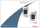
Apartment Intercom System
2 EASY
CONTENTS
RF CARD
RF CARD
RF CARD
A
1 2 3 4
56
0
7 8
9*#
B
RF CARD
A
1234
56
0
7 8
9*#
B
DMR21/S8
DMR21/F2 EP21/F3 EP21/S12DMR21/D32/F1
DMR21/D16 DMR21/S4/F1 DMR21/D8/F1
DMR21 TECHNICAL MANUAL
Installation Guide..........................................................................2
Modules. .......................................................................................4
Camera Module.........................................................................4
Keypad Module..........................................................................6
TFT Module. ...............................................................................11
Card Reader Module..................................................................12
Call Button Module ....................................................................14
Module Connection. ......................................................................16
CONFIGURATIONS......................................................................19
Common Door Station Setting ....................................................19
Software Update .........................................................................20
Tone Update ...............................................................................20
Namelist Update .........................................................................21
2-wire series

2 EASY
DESCRIPTION TERMINALS
PLACE NAMEPLATE
PARTS AND FUNCTIONS
INSTALLATION GUIDE
New generation Direct Call Apartments door stations are modular
design with a flexibility to combine modules.
For example,the video entry module can be assembled with card
reader module and/or with keypad module.
Additional combinations are available: TFT Screen Module with
Proximity Reader Module or Keypade Module. Calling to apartments
will be performed by Name List visible on the screen
Connection port
Stainless steel panel
316 mm
133 mm
Embedded box
RF CARD
L1 L2
1 2 3 4 5 6
ON DIP
Camera Lens
Speaker
Night View LED
ID Card Window
Status Indicator
Microphone
Nameplate
Call button
Screw hole
A B
• +12V: 12VDC power output
• LK-: Power ground
• LK+: Common contact of the relay
• NO.: Normally open contact of the relay
• EB+: Exit button positive connection port
• EB-: Exit button negative connection port
• JP-LK: Electic lock type setting
• SET : DIP switches for door station settings
• CN/KMB: Call button module connection port
• CN/T-COIL: Reserved
• CN/FUN: Touch sensor keypad module or TFT display module
connection port
• CN/WGN: Proximity reader module connection port
• Bus(L1,L2): Non-polarity bus line, connect to power supply
CN-LK
JP-LK
LK-
+12V
LK+
NO
EB-
EB+
SET
12V
TX1
RX1
GND
RX3
TX3
GND
5CL
GND
5DA
RST
INT
GND
12V
CLK
DAT
STR
C2
C1
CTR
GND
GND
VIO
POW
WG0
WG1
GND
12V
CN/KMB CN/T-COIL
CN/FUN CN/WGN
L1 L2
1 2 3 4 5 6
ON DIP
Press down and move right/left to open the transparent nameplate
cover. Then insert the name paper and put the cover back. Note that
the double row button panel can be opened both direction, single row
button can only be opened at right side
David
Calo
name paper
DMR21 Technical Manual-2-

2 EASY
INSTALLATION GUIDE
MOUNTING SYSTEM CONNECTION
Mounting with expanding panel
1 2
34
Cut a hole and install the wall box
Final resultUse screws to fasten the panel
Connect and plug bus line connector with cable
1 2
34
Cut a hole and install the wall box
Final result
Use the screws to fasten the panel
Connect and plug bus line connector with cable
Standard mounting
RF CARD
OFF ON
OFF ON
DBC4A
A B C D
DBC4A
A B C D
Impedance
switch
Impedance
switch
100~240VAC
BUS(IM) BUS(DS)
PC6
AC~
OFF ON
DBC4A
A B C D
Impedance
switch
Code=2
9
Code=3
1
Code=
30
Code=3
2
Code=
5
Code=
7
Code=
6
Code=
8
Code=
1
Code=
3
Code=
2
Code=
4
•
DMR21 Technical Manual -3-

2 EASY
ELECTRIC LOCK CONNECTION
SPECIFICATIONS
1) Door Lock Controlled with Internal Power
1. The door lock is limited to 12Vdc, and holding current must be less
than 250mA when using internal power supply mode
2. The Unlock Mode Parameter must be set to 0 (default).
3. Jumper set to 1-2 position for power-off-to-unlock safety
type(Normally closed mode); set to 2-3 position for power-on-to
-unlock type(Normally open mode ).
4. If different unlocking time is needed to be congured, change the
unlock time on door station,detailed information refer to DT system
technical guide
2) Door Lock Controlled with External Power
1. The external power supply must be used according to the lock
2. The jumper must be taken off before connecting
3. Setup the Unlock Mode Parameter for different lock types
• Power-on-to-Unlock type:Unlock Mode=0(default)
• Power-off-to-Unlock type:Unlock Mode=1
4. If different unlocking time is needed to be congured, change the
unlock time on door station,more detail information refer to DT system
technical guide
JP_LK
12V 300mA
Exit button
Jumper position in 2-3
+
-+12V
LK -
LK+
N.O.
EB-
EB+
1 2 3
Power-on-to-Unlock type:
Power-on-to-Unlock type:
12V 300mA
Jumper position in 1-2
+12V
LK -
LK+
N.O.
EB-
EB+
+
-
JP_LK
1 2 3
Exit button
Power-off-to-Unlock type:
Power-off-to-Unlock type:
+
+
-
-
+12V
LK - (GND)
LK+(COM)
N.O.
EB-
EB+
Take off the Jumper
JP_LK
Cut off the line
1 2 3
Exit button
+12V
LK - (GND)
LK+(COM)
N.O.
EB-
EB+
Take off the Jumper
+
+
-
-
JP_LK
Cut off the line
123
Exit button
• Power: 26Vdc(supplied by PC6)
• Power Consumption: 1W standby, 5W working
• Unlock Power output: 12Vdc,250mA
• Unlock time: 1~99s
• Working temperature: - 20ºC ~ +55ºC
• Dimensions: 316(H)x133(W)x48(D)mm
INSTALLATION GUIDE
DIP SWITCHES SETTING
Totally 6 bits can be congured by dip-switch. The switches can be
modied either before or after installation, but restarting the power is
needed whenever the switches have been modied
Bit-1 and Bit 2 is for door station ID settings. When multi door stations
are installed in the system, these two bit must be set correctly, the
rst door station set to 00, the second one set to 01, the third one set
to 10, the fourth one set to 11. If only one door station is installed, set
to 00.
Bit-3 is for single or double row button door station selection. If the
door station is a double row button, such as DMR21-D8, set this bit to
0. For single row button door station,set to 1.
Bit-4 is for button code selection. if use the default codes for each
button of the door station, set to 0. If use the programmed codes, set
to 1.(the code for each button can be programmed by software, detail
information refer to DT system technical guide)
Bit-5 is for unlocking time quick setting. 0 is the default setting,and the
default time is 1 second. If set to 1,the unlock time is 5 seconds(the
unlock time can be modied by door station or software)
Bit-6 is for activating the key A and key B. Normally key A and key B
is not activated(about the functions of key A and key B,please refer to
DT system technical guide ),Just when it set to 1,the key A and key B
is activated.
ON(1)
=
OFF(0)
=
ON
ON
ON
123456
DMR21 Technical Manual-4-

2 EASY
CAMERA MODULE
Note: Key A and key B can not be seen on the panel,they are cryptic.
Normally, key A and key B are not active. To activate the buttons,
just set the DIP6 to ON position
Attention: All settings will be canceled if the Restore Factory Setting
is activated. Include the modules setting, such as Proximity module,
Keypad module (even if the modules are not connected to the
Camera Module)
When in standby mode, short out the Exit Button Port(EB+,EB-),
then continuously toggle the DIP-6 switch for 4 times with a warning
sound of BP+, and the three Indicators will blink at the same time,
that means the Restore Factory Setting is in progress; If the three
Indicators turn off with a warning sound of BP+,it means the Restore
Factory Setting is nished
Please know that the DIP6 switch must be set to ON while the others
are set to OFF to carry on the following settings.
When the door station with Camera Module in standby:
(1)Press Key A, the Unlock indicator turns on with the warning sound
of BP+, BP;
(2)Press Key A again to set the Unlocking Mode to Normally Open
or Normally Closed. (Normally Open: the Status indicator blinks
ones with the warning sound of BP+; Normally Closed:the Status
indicator blinks twice with the warning sound of BP+, BP)
If TFT Module is connected, the info will be displayed on screen
When the door station with Camera Module in standby:
(1)Press Key A, the Unlock indicator turns on with the warning sound
of BP+, BP;
(2)Press and hold Key B to enter the Unlocking Time Delay Setting, a
warning sound of BP will be heard and the Status indicator blinks
one time per second
The counting of Unlocking Time is the times that Status indicator
blinks (the units is second). For example,the Status indicator blinks
for four times,that means the unlocking time is 4 seconds
When the door station with Camera Module in standby:
(1)Press and holld Key A for 3 seconds to enter the Warning Tune
Option Mode, the Status indicator turns on and the current tune
will be played
(2)Press Key A again to play next tune
(3)Press Key B to exit
When the door station with Camera Module is standby:
(1)Press Key B to enter Tune Volume Setting, the Talk indicator
turns on and plays the tune at current volume
(2)Press Key A to increase/decrease volume
(3)Press B to exit
If TFT Module is connected, the current Volume will be displayed on
screen
(1)During conversation, press and hold Key B for 3 seconds to
enter the Talk Volume Setting. The Talk indicator turns on with the
warning sound of BP+,BP
(2)Press Key A to increase/decrease volume
(3)Press Key B to exit
• Unlocking Mode Setting
• Unlocking Time Delay Setting
• Warning Tune Setting
• Tune Volume Setting
• Talk Volume Setting
Speaker
Camera lens
Night view LED
MIC
Invisible key A
Status indicator
Talk indicator
Unlock indicator
Invisible key B
MODULES
1. Parts and functions
2. Settings via touch button
3. Restore to factory setting
DMR21 Technical Manual -5-

2 EASY
KEYPAD MODULE
Input room number directly, the screen will be showed the room
number, press to start calling
Input password +”#” to unlock the door.
This section explains the settings of each function, please refer to the
tables
About the setting mode:
Input the master code to switch to the setting mode, and input the cor-
responding setting code to perform the settings for the function you
want. After settings have been made, input the following setting codes
to continue the setting operation. Press " " to exit the setting mode
Touch sensor
keypad
Call button
MODULES
1. Parts and functions
2. Keypad operation with TFT module
• Call Residents
• Password Unlocking
• Parameters Setting
• The example is set as cancel button and # as
conrm button,please refer to */# function setting
for detail information
• Forbid to slide to touch the digital keypad,it may
cause mistaken key,the correct operation is using
your nger to press the digit you desired
• You should press“conrm”button after nish input-
ting the code number each time,otherwise,the
operation will be cancelled automatically in 10s
Setting items Setting range Default
value
Setting
code
Reset all settings 1,2,3,4 -00
Setting the master code 1 ~ 12 digits
Valid keys:0 ~ 9 1234 01
Setting the key
illumination time
10 to 99 seconds/
continually lit 10 sec 02
Setting the unlock time 01 to 99 seconds 1 sec 03
Setting the unlock mode 0:opened/1:closed opened 04
Operation tone settings 0,1,2 on 05
Reset code settings 1,2,3,4 - 06
&# function settings 0:Normal/1:Reverse Normal 07
Call tone settings 0:Enable/1:Disable Enable 08
Interference resistant
grade settings Valid keys:0 ~ 5 2 09
SPK Adjustment Valid keys:0~9 5 11
Night light level Valid keys:0 ~ 5 4 13
Reserve Reserve Reserve 14~17
Setting the code
forTemporary1
1 ~ 12 digits
Valid keys:0~9 - 18
Setting the code
forTemporary2
1 ~ 12 digits
Valid keys:0~9 - 19
Setting the code
for user group1
1 ~ 12 digits
Number of codes:40
Valid keys:0~9
-20~59
Setting the code for
user group2
1 ~ 12 digits
Number of codes:40
Valid keys:0~9
- 60~99
Mounting
screw
DMR21 Technical Manual-6-

2 EASY
Input the master code
(Default: # # )
- All settings will restore to their
default value.
-
When power on or activate
the reset all setting item,the
keypad checking will carry out,
during this time,the key
illumination will blink and the
touching operation is forbidden,
after finish checking,the key
illumination will stop blinking
and sent out a long sound of beep
- The master code is allowed 1~12
digits
. T
he same code cannot be
set for both the user code and the
master code
. I
t is recommended
that you
change
the default master
code
- The unlock time can be set on
both monitor and door station,
and the valid value is the number
you set last
Beep+, Beep
Beep+, Beep Beep+, Beep Beep+, Beep Beep+, Beep
Beep+ Beep+ Beep+ Beep+
Inputting of code (ex.: 10)
range:00 or 10~99
Inputting of code (ex.: 09)
range:01~99
3.Setting the key
illumination time
4.Setting the
unlock time
2.Setting the master code
(Default 1234) (Default 10s) (Default 1s)
Inputting of new master code
(ex.: 4321)(1~12 digits)
Input the setting code.
Inputting of code
Input the setting code.
1.Reset all settings
00+#
1234+# 4321+#
01+#
10+# 09+#
Input the setting code.
02+#
Input the setting code.
03+#
- If the key illumination time is set
to 00,the key illumination will light
up all the time when power on.
- If the key illumination time is set to
10~99,the key illumination will light
up for 10~99 seconds.At this mode,
the key illumination lights off in
standby mode, touching any digital
key can illuminate,but this is the
invalid digit.
-
When the “ cancel” key is pressed, the indicator will show its standby color, the buzzer beeps, and the system
exits the setting mode
-
When there isn’t any operation in 10s, the buzzer beeps, and the system exits the setting mode
Beep, Beep+
*
-
When setting failure, the buzzer beeps
MODULES
DMR21 Technical Manual -7-

2 EASY
Input the master code
(Default: # #
Beep+, Beep Beep+, Beep Beep+, Beep Beep+, Beep
Beep+
Beep+Beep+ Beep+
7.Reset code setting 8. &# function setting 6.Setting operation tone
(Default ON) (Default Normal)
(Default 0(Opened))
Input the setting code.
Inputting of code
Input the setting code.
5.Setting the unlock mode
04+# 05+#
range:0:(open)/1:(close)
1+#
0/1 0/1 0/1
1+# 1+#1234+#
Input the setting code.
06+#
Input the setting code.
07+#
(ex.: 1)
Inputting of code Inputting of code Inputting of code
range:0:(on)/1:(off)
(ex.: 1)
range:0:(normal)/1:(reverse)
(ex.: 1)
*
*
*
- The unlock mode can be set on
both monitor and door station,
and the valid value is the number
you set last
- When the operation tone is
set to 0,pressing the digital
keypad will sent out a sound
of beep.
- When the operation tone is
set to 1,pressing the digital
keypad will blink one time.
- Cancel all the passwords except
the master code.
- Restore the master code to
default value(1,2,3,4)
- When the item is set to 0,press
the button to cancel the input,
and press the # button to confirm
the input.
- When the item is set to 1,press
the # button to cancel the input,
and press the button to confirm
the input .
Beep+, Beep
-
When the “ cancel” key is pressed, the indicator will show its standby color, the buzzer beeps, and the system
exits the setting mode.
-
When there isn’t any operation in 10s, the buzzer beeps, and the system exits the setting mode.
Beep, Beep+
*
-
When setting failure, the buzzer beeps.
MODULES
DMR21 Technical Menu-8-

2 EASY
Input the master code
(Default: # #
Beep+, Beep Beep+, Beep
Beep+ Beep+
10.Interference resistant
grade setting
Input the setting code. Input the setting code.
9. Call tone setting
08+#
0/1
1+#
09+#
Inputting of code (ex.: 3)
range:0~5
3+#
Inputting of code (ex.: 1)
range:0(enable)/1:(disable)
(Default 2)
(Default enable)
-
The larger you set the
interference resistant grade,
the stronger it will be,but the
sensitivity of the keypad will
be more lower.
- The interference resistant
grade setting also will activate
the keypad checking
-
If the item is set to 0,the unit will
respond a call tone when pressing
the “CALL” button.
- If set to 1, the unit will have no
respons when pressing the
“CALL” button
Beep+, Beep
Beep+
11.SPK volume adjust
setting
Input the setting code. Input the setting code.
11+#
Inputting of code (ex.: 5)
range:0~9
5+#
(Default:4)
- Unlock via password is still
available even when the door
station is talking
state
.
- When door station is talking,
you can enter the Master code
(the LED turns white upon that)
to activate the volume adjusting
function:
Speaker adjustment: 3 (up),
6 (down)
Beep+, Beep
Beep+
12.Night light level
setting
13+#
Inputting of code (ex.: 3)
range:0~5
3+#
(Default 4)
- Night Light Level:0~5. -
The higher the number, the
brighter the lights
Beep+, Beep
-
When the “ cancel” key is pressed, the indicator will show its standby color, the buzzer beeps, and the system
exits the setting mode.
-
When there isn’t any operation in 10s, the buzzer beeps, and the system exits the setting mode.
Beep, Beep+
*
-
When setting failure, the buzzer beeps.
MODULES
DMR21 Technical Manual -9-

2 EASY
Input the master code
(Default: # # Beep+, Beep
Beep+, Beep Beep+, Beep Beep+, Beep Beep+, Beep
Beep+ Beep+ Beep+ Beep
Inputting of code (ex.: 2011)
1~12 digits
Inputting of code (ex.: 2012)
1~12 digits
18.Setting the code
for user group1
19.Setting the code
for user group2
17.Setting the code
forTemporary2
Input the setting code. Input the setting code.
16.Setting the code
forTemporary1
18+# 19+# 21+# 60+#
2011+#
Inputting of code (ex.: 1006)
1~12 digits
1006+#
Inputting of code (ex.: 2011)
1~12 digits
2010+# 2012+#
Input the setting code.
(ex.:21)
Input the setting code.
(ex.:60)
20~59 60~99
- When input the correct temporary password to release the door,
the system will clear the temporary password after 60 seconds
automatically.But you should know that the password is valid within
60 seconds after inputing the correct temporary password
- The temporary1 is used to release the first lock,and the temporary
2 is used to release the second lock(the second lock need external
device to support).
- If the password length exceeds 12 digits, the system will sent out
the sound of “beep,beep,beep,beep”,and the digitals you input before
will be cleared at the same time.
- The temporary code can not be set the same as the master code
and user code.
- The user code group1 is used to release the first lock,and the user
code group2 is used to release the second lock (the second lock
need external device to support).
- The user code group1 and user code code group2 can contain 40
group passwords
- If the password length exceeds 12 digits, the system will sent out
the sound of “beep,beep,beep,beep”,and the digitals you input
before will be cleared at the same time.
- The user code can not be set the same as the master code and
temporary code.
-
When the “ cancel” key is pressed, the indicator will show its standby color, the buzzer beeps, and the system
exits the setting mode.
-
When there isn’t any operation in 10s, the buzzer beeps, and the system exits the setting mode.
Beep, Beep+
*
-
When setting failure, the buzzer beeps.
MODULES
DMR21 Technical Manual-10-

2 EASY
TFT DISPLAY MODULE
1. Parts and functions
2. Features
3. Functions
3.5 inch TFT
screen
Touch sensor
button
Mounting
screw
• Calling via name list
• 3.5 inch TFT display
• Operation visualization
• With three touch buttons
• Easy update of name list
• Standby
• Name List Calling
• Calling Display
• Conversation
• Keypad operation
This is the start point in standby mode, It can be customized.(More
details refer to UI Update section)
In standby mode, press to show the name list. Press or
to select name. After that, press to call the corresponding user.
Press * (Keypad Module) to cancel the call.
This is the user interface of calling process. (Know that if the name
list is created, the resident’s name will be showed on screen)
Press * (Keypad Module) to cancel the call.
This is the user interface of conversation process.
The conversation time will be recorded.
Press * (Keypad Module) to cancel the call.
i) When in standby mode, input the number by pressing keypad, the
room number will be showed on screen.
ii) When in standby mode, press # key,a password will be asked. This
is the user interface of password input.
MODULES
DMR21 Technical Manual -11-

2 EASY
CARD READER MODULE
1. Parts and functions
2. Features
3. Card Operation
Swiping card
area
LED indicator
Mounting
screw
• Up to 320 user cards can be registered by door station
• Easy management with indicators and sound hints
• Two Master Cards are supplied, one MASTER CARD ADD
and one MASTER CARD DELETE
• The distance of card reading is from 3 to 5 cm
• The Master Cards are necessary when you add or delete user
cards. Please keep them safe for future use
It is possible to create new Master Cards, the old ones are invalid
automatically
• Combination with ID module
iii) When input admin code,a Setting Code will be asked on TFT
screen.
When registered ID card will be presented to a Proximity Reader,
“Door open” message will be showed on TFT Display Module screen
This is the user interface of adding card, please know that the user
interface of delete card or initialization is similar as the following pic-
ture shows.
• Master Card Setting
Power on and short out EB+,EB- , a sound of “BP+” will be sent out,
and the Unlock indicator will turn on
Toggle DIP4 switch for four times, a sound of “BP+,BP” will be sent
out , the Talk indicator and the Unlock indicator will turn on
Show the ADD CARD, a sound of “BP+” will be sent out, the Unlock
indicator is turned on.
Show the DELETE CARD, a sound of “BP+” will be sent out, and all
indicators will be turned off. After 10 seconds, it will exit the Master
Card Setting automatically
MODULES
DMR21 Technical Manual-12-

2 EASY
Power on and short out EB+,EB- , a sound of “BP+” will be sent out,
and the Unlock indicator will turn on
• User Card Setting
In standby mode, show the MASTER CARD ADD, it will sound
“BP+,BP”, the Talk indicator will turn on
Input the room number you need to set (0 is default). Show User
Cards, it will sound “BP+”, and the Talk indicator blinks ones. You
can continuously show User Cards
Show the MASTER CARD ADD to exit out Add User Card Setting,
it will sound “BP,BP+”, and all indicators are turned off. (without any
operation for 10 seconds, it will return to standby mode)
In standby mode, show the MASTER CARD DELETE, it will sound
“BP+,BP”, and the Unlock indicator is turned on. and the Delete
Card Mode is activated.
In standby mode, show the MASTER CARD DELETE, it will sound
“BP+,BP”, and the Unlock indicator will turn on
Show the MASTER CARD ADD, it will sound “BP+,BP”, and the Talk
indicator and the Unlock indicator will turn on
Show the MASTER CARD ADD, it will sound “BP”, the Talk indicator
and the Unlock indicator will blink, and after 10 seconds, it will
return to standby mode
i) By PC
ii) By SD Card
--Delete by room number: Input the room code, it will sound “BP+”,
and the Unlock indicator blinks one time,all associated cards will be
deleted..
--Delete by User Card: Show the User Cards which you need to
delete. It will sound “BP+”, and he Unlock indicator blinks one time.
(You can continuously show user cards that you need to delete)
In Delete Card Mode :
Show the MASTER CARD DELETE to exit out Delete Card Mode.
It will sound “BP,BP+”, and all indicators are turned off. (without any
operation for 10 seconds, it will return to standby mode)
i) Add User Card
ii) Delete User Card
iii) Format Card
iiii) Card Database
MODULES
The informations will be displayed on screen when some operations
are carried on, such as Master Card Setting, Add User Card and
Delete User Card etc.
For example,swipe the user card, the info of “Door Open” will be dis-
played on screen.
4. Combination
• Combination With TFT
Module
RF CARD
A
1234
56
0
78
9*#
B
DMR21 Technical Manual -13-

2 EASY
1) Master Card Setting(Reserve)
2) Add Card Setting(Reserve)
2) Delete Card Setting(Reserve)
• Combination With Keypad & TFT Modules
• Combination With Keypad Module
MODULES
CALL BUTTON MODULE
1. Parts and functions
2. Call codes
Call button
Call button
Name plate
Name plate
Double row call button module
Single row call button module
Mounting
screw
Mounting
screw
The DMR21 automatically assigns the call codes to the connected
module’s buttons. Regardless of the structure of the call button mod-
ule, the button numbers are listed from the top to bottom and from
left to right (in the case of double row buttons):
In the case of double row buttons:
* Examples:
01 02
03 04
05 06
07 08
RF CARD
01 02
03 04
05 06
07 08
09 10
11 12
13 14
15 16
09 10
11 12
13 14
15 16
17 18
19 20
21 22
23 24
25 26
27 28
29 30
31 32
01 02
03 04
05 06
07 08
• DIP3 switch set Off
1 2 34 5 6
ON
DMR21 Technical Manual-14-

2 EASY
MODULES
3. Address description
For single row of buttons
• DIP3 switch set Off
• DIP3 switch set to on
1 2 34 5 6
ON
RF CARD RF CARD
02
04
06
08
02
04
06
08
02
04
06
08
10
12
14
16
10
12
14
16
18
20
22
24
26
28
30
32
RF CARD RF CARD
01
02
03
04
01
02
03
04
01
02
03
04
05
06
07
08
05
06
07
08
09
10
11
12
13
14
15
16
1 2 34 5 6
ON
01
02
03
04
05
06
07
08
NO. Functions
Call apartment 01
Call apartment 02
Call apartment 03
Call apartment 04
Call apartment 05
Call apartment 06
Call apartment 08
Call apartment 07
DMR21 Technical Manual -15-

2 EASY
MODULES CONNECTION
TERMINAL DESCRIPTION
• Video entry module
• Card reader module
• Call button module
• Keypad and TFT module
OUTPUT
INPUT
OUTPUT
INPUT
1
1
1
1
1
2
2
2
2
2
3
3
3
4
4
5
5
6
6
7
2
3
1
1
2
1 2
7
8
8
NO.
NO.
NO.
NO.
Name
Name
Name
Name
Descriptions
Descriptions
Descriptions
Descriptions
SET
CN/FUN_IN
INPUT
CN/FUN_OUT
OUTPUT
JWGN1
JP-LK
JKB'
JKB
CN-LK
CN/KMB
CN/FUN
CN/WGN
CN/T-COIL
Bus
DIP switches for system congurations
Connect to CN/FUN of video entry module
Connect to CN/KMB of video entry module
Connect to CN/WGN of video entry module
For electronic lock safety type setting
Connect to next keypad or TFT module
Connect to next call button module
Connect to next call button module
Connect to next call button module
Call button module connection port
Reserved
Non-polarity bus line,connect to power comb unit
Electric lock and exit button connection port
Card reader module connection port
Touch sensor keypad module or TFT display
module connection port
DMR21 Technical Manual-16-

2 EASY
MODULES CONNECTION
CONNECTIONS
• DMR21/D16 • DMR21/T4/D8
• DMR21/ID/S4 • DMR21/ID/KP
INPUT
INPUT
OUTPUT
OUTPUT
CN/KMB
RF CARD
OUTPUT
INPUT
INPUT
CN/KMB
CN/WGN
INPUT
OUTPUT
INPUT
CN/KMB
CN/FUN
OUTPUT
INPUT
CN/WGN
RF CARD
A
1 2 3
4
5 6
0
78
9*#
B
OUTPUT
INPUT
CN/FUN
DMR21 Technical Manual -17-

2 EASY
• DMR21/S8+F3
• DMR21/ID/KP
RF CARD
A
1234
56
0
78
9*#
B
INPUT
INPUT
OUTPUT
OUTPUT
OUTPUT
INPUT
OUTPUT
INPUT
OUTPUT
INPUT
CN/KMB
CN/FUN CN/WGN
RF CARD
OUTPUT
INPUT
INPUT
OUTPUT
INPUT
OUTPUT
INPUT
OUTPUT
INPUT
OUTPUT
CN/KMB
CN/WGN
MODULE CONNECTION
DMR21 Technical Manual-18-

2 EASY
COMMON DOOR STATION SETTING
i) Create a TXT le, and named Namelist.
ii) Open the Namelist.txt le, and input 5 [ ] symbols. Each [ ] symbol
has its meaning, see the following picture.
iii) Edit Namelist.txt le. For example, as the following picture.
Button: DMR21 button which you need to set.
Name: It will be displayed on TFT module.
Gateway: Set the Gateway mode recording to BDU address. [08~15]
means BDU address 01~08
Router: Set the Router mode recording to BDU address.[01~08]
means BDU address 01~08
Address: Set the monitor address you want to call.
[001][Alan_1][08][00][01]
Press the rst button, it would call the monitor 01 in BDU 1, and it is
displayed Alan_1 on TFT module.
This section is reserved
For more details please refer to the following section of Namelist
Update By SD Card
Description:
Denition:
• Calling By Buttons
• Calling By Namelist
• Calling By Keypad Module
Press the call button to call corresponding monitors
i) Press touch sensor button to show the name list
ii) Select the name,then press touch sensor button to call
Input the Aprt number on keypad (with keypad module) and press
touch sensor button to call the corresponding monitor
DMR21 Technical Manual -19-
CONFIGURATION
1.Namelist.txtleSetting:
4.Calling
2.Work Mode Setting:
3.Namelist Update:

2 EASY
CONFIGURATIONS
TONE UPDATESOFTWARE UPDATE
1. Format SD card
2. Copy the Update Ring.bin le to SD card by computer.
1. Format SD card
2. Copy the Update DMR21.bin le to SD card by computer.
3.Update ringtone:
i) Power on the DMR21, and set DIP6 switch to ON, as the following
picture shows:
3.Update software:
i) Power on the DMR21, and set DIP6 switch to ON, as the following
picture shows:
ii) Insert SD card to slot.
ii) Insert SD card to slot.
iii) A long warning sound of “BP+” will be sent out, and the Talk indi-
cator is turned on.
iii) A long warning sound of “BP+” will be sent out, and the Status
indicator is turned on.
iii) After 3 seconds, all the indicators are turned on.
iiii) After 20 seconds, a long sound of “BP+” will be sent out, and all
indicators are turned off.It means Software update is nished.
iiii) After 20 seconds, a long sound of “BP+” will be sent out, and the
Talk indicator is turned off, It means Tone update is nished.
DIP6=ONDIP6=ON
1 2 3 4 5 6
ON
1 2 3 4 5 6
ON
INPUT
CN/KMB
CN/WGN
INPUT
CN/KMB
CN/WGN
DMR21 Technical Manual-20-
/