2easy DMR12/D16 Quick Installation Manual
- Category
- Door intercom systems
- Type
- Quick Installation Manual
This manual is also suitable for
2easy DMR12/D16 is a door station that can be used to call a user in an apartment and control the electronic lock opening. It has a speaker, camera lens, microphone, and DIP switches for system configurations. The DIP switches can be used to set the door station ID, select between single line button or double line button door station, select button code, set unlocking time, and set door station ID settings. The door station also has terminals for connecting to a power supply, electronic lock, exit button, and bus line.
2easy DMR12/D16 is a door station that can be used to call a user in an apartment and control the electronic lock opening. It has a speaker, camera lens, microphone, and DIP switches for system configurations. The DIP switches can be used to set the door station ID, select between single line button or double line button door station, select button code, set unlocking time, and set door station ID settings. The door station also has terminals for connecting to a power supply, electronic lock, exit button, and bus line.


-
 1
1
-
 2
2


2easy DMR12/D16 Quick Installation Manual
- Category
- Door intercom systems
- Type
- Quick Installation Manual
- This manual is also suitable for
2easy DMR12/D16 is a door station that can be used to call a user in an apartment and control the electronic lock opening. It has a speaker, camera lens, microphone, and DIP switches for system configurations. The DIP switches can be used to set the door station ID, select between single line button or double line button door station, select button code, set unlocking time, and set door station ID settings. The door station also has terminals for connecting to a power supply, electronic lock, exit button, and bus line.
Ask a question and I''ll find the answer in the document
Finding information in a document is now easier with AI
Related papers


Other documents
-
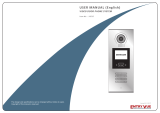 Entryvue 14215 User manual
-
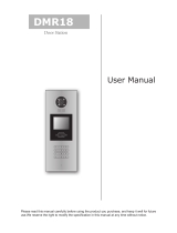 Schick Handel DMR18 User manual
-
Elan COM2 Installation guide
-
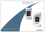 Entryvue 13536 User manual
-
Videx DIGITAL VX2200 System Manual
-
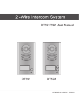 FERMAX DT592 User manual
-
urmet domus Miwi 1202/952 User manual
-
V-Tec VT596/KP User manual
-
-
 fortessa FTDEV1P Operating instructions


