Extron DTP2 T 203 User manual
- Category
- Video switches
- Type
- User manual

User Guide
DTP2T203
DTP Systems
Three-input, Multi-format Switching Transmitter
68‑3117‑01 Rev. A
08 19

Safety Instructions
Safety Instructions • English
WARNING: This symbol, ,when used on the product, is
intended to alert the user of the presence of uninsulated dangerous
voltage within the product’s enclosure that may present a risk of electric
shock.
ATTENTION: This symbol, , when used on the product, is intended
to alert the user of important operating and maintenance (servicing)
instructions in the literature provided with the equipment.
For information on safety guidelines, regulatory compliances, EMI/EMF
compatibility, accessibility, and related topics, see the Extron Safety and
Regulatory Compliance Guide, part number 68‑290‑01, on the Extron
website, www.extron.com.
Sicherheitsanweisungen • Deutsch
WARNUNG: Dieses Symbol auf dem Produkt soll den Benutzer
darauf aufmerksam machen, dass im Inneren des Gehäuses dieses
Produktes gefährliche Spannungen herrschen, die nicht isoliert sind und
die einen elektrischen Schlag verursachen können.
VORSICHT: Dieses Symbol auf dem Produkt soll dem Benutzer in
der im Lieferumfang enthaltenen Dokumentation besonders wichtige
Hinweise zur Bedienung und Wartung (Instandhaltung) geben.
Weitere Informationen über die Sicherheitsrichtlinien, Produkthandhabung,
EMI/EMF‑Kompatibilität, Zugänglichkeit und verwandte Themen finden Sie in
den Extron‑Richtlinien für Sicherheit und Handhabung (Artikelnummer
68‑290‑01) auf der Extron‑Website, www.extron.com.
Instrucciones de seguridad • Español
ADVERTENCIA: Este símbolo, , cuando se utiliza en el producto,
avisa al usuario de la presencia de voltaje peligroso sin aislar dentro del
producto, lo que puede representar un riesgo de descarga eléctrica.
ATENCIÓN: Este símbolo, , cuando se utiliza en el producto, avisa
al usuario de la presencia de importantes instrucciones de uso y
mantenimiento recogidas en la documentación proporcionada con el
equipo.
Para obtener información sobre directrices de seguridad, cumplimiento
de normativas, compatibilidad electromagnética, accesibilidad y temas
relacionados, consulte la Guía de cumplimiento de normativas y seguridad
de Extron, referencia 68‑290‑01, en el sitio Web de Extron, www.extron.com.
Instructions de sécurité • Français
AVERTISSEMENT : Ce pictogramme, , lorsqu’il est utilisé sur le
produit, signale à l’utilisateur la présence à l’intérieur du boîtier du
produit d’une tension électrique dangereuse susceptible de provoquer
un choc électrique.
ATTENTION : Ce pictogramme, , lorsqu’il est utilisé sur le produit,
signale à l’utilisateur des instructions d’utilisation ou de maintenance
importantes qui se trouvent dans la documentation fournie avec le
matériel.
Pour en savoir plus sur les règles de sécurité, la conformité à la
réglementation, la compatibilité EMI/EMF, l’accessibilité, et autres sujets
connexes, lisez les informations de sécurité et de conformité Extron, réf.
68‑290‑01, sur le site Extron, www.extron.com.
Istruzioni di sicurezza • Italiano
AVVERTENZA: Il simbolo, , se usato sul prodotto, serve ad
avvertire l’utente della presenza di tensione non isolata pericolosa
all’interno del contenitore del prodotto che può costituire un rischio di
scosse elettriche.
ATTENTZIONE: Il simbolo, , se usato sul prodotto, serve ad
avvertire l’utente della presenza di importanti istruzioni di funzionamento
e manutenzione nella documentazione fornita con l’apparecchio.
Per informazioni su parametri di sicurezza, conformità alle normative,
compatibilità EMI/EMF, accessibilità e argomenti simili, fare riferimento
alla Guida alla conformità normativa e di sicurezza di Extron, cod. articolo
68‑290‑01, sul sito web di Extron, www.extron.com.
Instrukcje bezpieczeństwa • Polska
OSTRZEŻENIE: Ten symbol, , gdy używany na produkt, ma na celu
poinformować użytkownika o obecności izolowanego i niebezpiecznego
napięcia wewnątrz obudowy produktu, który może stanowić zagrożenie
porażenia prądem elektrycznym.
UWAGI: Ten symbol, , gdy używany na produkt, jest przeznaczony do
ostrzegania użytkownika ważne operacyjne oraz instrukcje konserwacji
(obsługi) w literaturze, wyposażone w sprzęt.
Informacji na temat wytycznych w sprawie bezpieczeństwa, regulacji
wzajemnej zgodności, zgodność EMI/EMF, dostępności i Tematy pokrewne,
zobacz Extron bezpieczeństwa i regulacyjnego zgodności przewodnik, część
numer 68-290-01, na stronie internetowej Extron, www.extron.com.
安全说明 • 简体中文
警告: 产品上的这个标志意在警告用户该产品机壳内有暴露的危险 电压,
有触电危险。
注意: 产品上的这个标志意在提示用户设备随附的用户手册中有
重要的操作和维护(维修)说明。
关于我们产品的安全指南、遵循的规范、EMI/EMF 的兼容性、无障碍
使用的特性等相关内容,敬请访问 Extron 网站 , www.extron.com,参见
Extron 安全规范指南,产品编号 68-290-01。

안전 지침 • 한국어
경고: 이 기호 가 제품에 사용될 경우, 제품의 인클로저 내에 있는
접지되지 않은 위험한 전류로 인해 사용자가 감전될 위험이 있음을
경고합니다.
주의: 이 기호 가 제품에 사용될 경우, 장비와 함께 제공된 책자에 나와
있는 주요 운영 및 유지보수(정비) 지침을 경고합니다.
안전 가이드라인, 규제 준수, EMI/EMF 호환성, 접근성, 그리고 관련 항목에
대한 자세한 내용은 Extron 웹 사이트(www.extron.com)의 Extron 안전 및
규제 준수 안내서, 68-290-01 조항을 참조하십시오.
安全記事 • 繁體中文
警告: 若產品上使用此符號,是為了提醒使用者,產品機殼內存在著
可能會導致觸電之風險的未絕緣危險電壓。
注意 若產品上使用此符號,是為了提醒使用者,設備隨附的用戶手冊中有
重 要 的 操 作 和 維 護( 維 修 )説 明 。
有關安全性指導方針、法規遵守、EMI/EMF 相容性、存取範圍和相關主題的詳細資
訊,請瀏覽 Extron 網站:www.extron.com,然後參閱《Extron 安全性與法規
遵守手冊》,準則編號 68-290-01。
安全上のご注意 • 日本語
警告: この記号 が製品上に表示されている場合は、筐体内に絶縁されて
いない高電圧が流れ、感電の危険があることを示しています。
注意:この記号 が製品上に表示されている場合は、本機の取扱説明書に
記載されている重要な操作と保守(整備)の指示についてユーザーの注意
を喚起するものです。
安全上のご注意、法規厳守、EMI/EMF適合性、その他の関連項目に
つ い て は 、エ ク スト ロ ン の ウェ ブ サ イト www.extron.com よ り 『 Extron Safety
and Regulatory Compliance Guide』 ( P/N 68‑290‑01) をご覧ください。
Copyright
© 2019 Extron Electronics. All rights reserved.
Trademarks
All trademarks mentioned in this guide are the properties of their respective owners.
The following registered trademarks(
®
), registered service marks(
SM
), and trademarks(
TM
) are the property of RGBSystems, Inc. or
ExtronElectronics (see the current list of trademarks on the Terms of Use page at www.extron.com):
Registered Trademarks
(
®
)
Extron, Cable Cubby, ControlScript, CrossPoint, DTP, eBUS, EDID Manager, EDID Minder, Flat Field, FlexOS, Glitch Free. Global Configurator,
GlobalScripter, GlobalViewer, Hideaway, HyperLane, IPIntercom, IPLink, KeyMinder, LinkLicense, LockIt, MediaLink, MediaPort, NetPA,
PlenumVault, PoleVault, PowerCage, PURE3, Quantum, Show Me, SoundField, SpeedMount, SpeedSwitch, StudioStation, SystemINTEGRATOR,
TeamWork, TouchLink, V-Lock, VideoLounge, VN-Matrix, VoiceLift, WallVault, WindoWall, XTP, XTPSystems, and ZipClip
Registered Service Mark
(SM)
: S3 Service Support Solutions
Trademarks
(
™
)
AAP, AFL (Accu-RateFrameLock), ADSP(Advanced Digital Sync Processing), Auto-Image, AVEdge, CableCover, CDRS(ClassD
Ripple Suppression), Codec Connect, DDSP(Digital Display Sync Processing), DMI (DynamicMotionInterpolation), DriverConfigurator,
DSPConfigurator, DSVP(Digital Sync Validation Processing), eLink, EQIP, Everlast, FastBite, FOX, FOXBOX, IP Intercom HelpDesk, MAAP,
MicroDigital, Opti-Torque, PendantConnect, ProDSP, QS-FPC(QuickSwitch Front Panel Controller), RoomAgent, Scope-Trigger, ShareLink, SIS,
SimpleInstructionSet, Skew-Free, SpeedNav, Triple-Action Switching, True4K, Vector™ 4K , WebShare, XTRA, and ZipCaddy

FCC Class A Notice
This equipment has been tested and found to comply with the limits for a Class A digital device,
pursuant to part15 of the FCC rules. The ClassA limits provide reasonable protection against harmful
interference when the equipment is operated in a commercial environment. This equipment generates,
uses, and can radiate radio frequency energy and, if not installed and used in accordance with the
instruction manual, may cause harmful interference to radio communications. Operation of this
equipment in a residential area is likely to cause interference. This interference must be corrected at
the expense of the user.
ATTENTION:
• The Twisted Pair Extension technology works with unshielded twisted pair (UTP)
or shielded twisted pair (STP) cables; but to ensure FCC Class A and CE
compliance, STP cables and STP Connectors are required.
• La technologie extension paires torsadées fonctionne avec les câbles paires
torsadées blindées(UTP) ou non blindées(STP). Afin de s’assurer de la
compatibilité entre FCC ClasseA et CE, les câbles STP et les connecteurs STP
sont nécessaires.
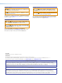
NOTES:
• This unit was tested with shielded I/O cables on the peripheral devices. Shielded
cables must be used to ensure compliance with FCC emissions limits.
• For more information on safety guidelines, regulatory compliances, EMI/EMF
compatibility, accessibility, and related topics, see the Extron Safety and
Regulatory Compliance Guide on the Extron website.

Conventions Used in this Guide
Notifications
The following notifications are used in this guide:
CAUTION: Risk of minor personal injury.
ATTENTION : Risque de blessuremineure.
ATTENTION:
• Risk of property damage.
• Risque de dommages matériels.
NOTE: A note draws attention to important information.
TIP: A tip provides a suggestion to make working with the application easier.
Software Commands
Commands are written in the fonts shown here:
^AR Merge Scene,,0p1 scene 1,1 ^B 51 ^W^C.0
[01] R 0004 00300 00400 00800 00600 [02] 35 [17] [03]
E X! *X1&* X2)* X2#* X2! CE}
NOTE: For commands and examples of computer or device responses mentioned
in this guide, the character “0” is used for the number zero and “O” is the capital
letter “o.”
Computer responses and directory paths that do not have variables are written in the font
shown here:
Reply from 208.132.180.48: bytes=32 times=2ms TTL=32
C:\Program Files\Extron
Variables are written in slanted form as shown here:
ping xxx.xxx.xxx.xxx —t
SOH R Data STX Command ETB ETX
Selectable items, such as menu names, menu options, buttons, tabs, and field names are
written in the font shown here:
From the File menu, select New.
Click the OK button.
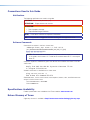
Specifications Availability
Product specifications are available on the Extron website, www.extron.com.
Extron Glossary of Terms
A glossary of terms is available at http://www.extron.com/technology/glossary.aspx.


viiDTP2 T 203 • Contents
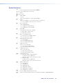
Contents
Introduction ................................................1
About this Guide .................................................. 1
About the DTP2T203 ......................................... 1
Features .............................................................. 1
Application Diagram ............................................ 4
Installation .................................................. 5
Installation Overview ............................................ 5
Rear Panel Features ............................................ 6
Wiring Connections ........................................... 10
Power Connector .......................................... 10
Wiring the LAN Connector ............................. 12
Wiring the TP Connector and Cable
Recommendations ....................................... 12
Remote RS-232 Control ................................ 13
Over TP RS-232 and IR Control ..................... 14
Contact In Port .............................................. 14
Tally Out Port ................................................. 15
Securing an HDMI Connector ............................ 15
Operation..................................................16
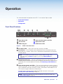
Front Panel Features .......................................... 16
Operations......................................................... 17
Powering on the Switching Transmitter .......... 17
Selecting an Input .......................................... 17
Resetting ....................................................... 18
Front Panel Lockout (Executive Mode) ........... 18
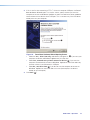
Configuration ..................................................... 18
Connecting to the USB Port .......................... 18
Enabling Auto-Input Switching ....................... 20
EDID Minder .................................................. 21
HDCP ............................................................ 21
TMDS Output Format .................................... 22
Color Depth and Deep Color Support ............ 22
Audio Configuration ........................................... 22
Input Audio Configuration .............................. 22
Analog Audio Follow ...................................... 23
Analog Audio Mute ........................................ 23
TMDS Output Audio Configuration ................. 23
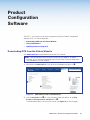
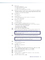
Product Configuration Software ................. 24
Downloading PCS from the Extron Website ....... 24
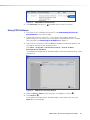
Using PCS Software .......................................... 25
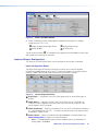
Input and Output Configuration ...................... 26
EDID Minder .................................................. 28
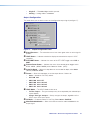
General Settings ............................................ 30
AV Controls Panel .......................................... 34
Device Menu.................................................. 34
PCS Help File ................................................ 35
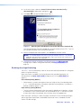
Updating Firmware Using PCS .......................... 35
Downloading the DTP2 T 203 Firmware ......... 35
Loading the Firmware to the Switcher ............ 36
SIS Commands .........................................39
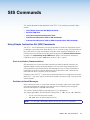
Using Simple Instruction Set (SIS) Commands ... 39
Host-to-switcher Communications ................ 39
Switcher-initiated Messages .......................... 39
Error Responses ............................................ 40
Timeout ......................................................... 40
Unsolicited Responses .................................. 40
Ethernet (LAN) Port............................................ 40
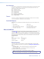
Using the Command and Response Table ......... 41
Symbol Definitions ......................................... 42
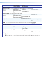
Command and Response Table for SIS
Commands ..................................................... 46
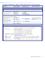
Command and Response Table for CEC
Communications SIS Commands .................... 54

DTP2 T 203 • Contents viii
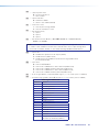
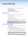
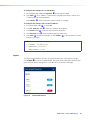
Internal Web Page ..................................... 56
Web Page Overview .......................................... 56
Accessing the Internal Web Page ...................... 56
Turning Off Compatibility Mode .......................... 57
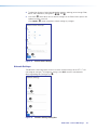
Configuring the Device Using the Internal Web
Page ................................................................ 57
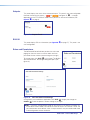
Device Info ..................................................... 58
Device Status ................................................ 58
Network Settings ........................................... 59
Inputs ............................................................ 60
Outputs ......................................................... 61
RS-232 .......................................................... 61
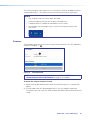
Roles and Permissions .................................. 61
Firmware ....................................................... 62
Mounting ..................................................64
Mounting the DTP2T203 ................................. 64
Tabletop Use ................................................. 64
Rack Mounting .............................................. 64
Furniture Mounting......................................... 64

DTP2 T 203 • Introduction 1
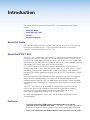
Introduction
This section gives an overview of the Extron DTP2T203 switching transmitter. Topics
include:
• About this Guide
• About the DTP2T203
• Features
• Application Diagram
About this Guide
This guide describes the function, installation, and operation of the DTP2 T 203 switching
transmitter. In this guide, the DTP2 T 203 is commonly referred to as a “transmitter,”
“switcher,” “switching transmitter,” or DTP2 T 203.
About the DTP2T203
The DTP2T203 is a three-input, multi-format DTP2 switching transmitter consisting of one
DisplayPort input and two HDMI inputs, one analog audio input, and a DTP/HDBT output.
It switches and extends digital video with resolutions up to 4K@60Hz 4:4:4, analog audio,
bi-directional RS-232 and IR over one shielded twisted pair (STP) cable capable of switching
and extending a DTP/HDBT signal up to 330feet (100meters).
It is an HDCP compliant switcher, which supports video resolutions up to 4K@60Hz,
including Deep Color, as well as data rates up to 18Gbps, 3D, Lip Sync, HDCP 2.2, HDBT
compatibility, and HD lossless audio formats. The device also features EDID Minder for
managing EDID, and Key Minder for managing HDCP to DTP, DTP2, and HDBase-T (HDBT)
receivers.
The switcher features can be integrated into many applications that use a DTP-equipped
receiver or HDBT-capable products. The switcher can be remotely powered over the
shielded twisted pair cable by a DTP2-enabled product. Alternatively, it can be configured
to provide power to a connected DTP2 receiver, allowing both devices to share one power
supply.
The DTP2T203 switcher can be controlled via the front panel, the RS-232 interface,
USB, or LAN. Inputs can be selected by pressing the front panel buttons, enabling
auto-input switching, entering Simple Instruction Set (SIS) commands, or using
Extron Product Configuration Software (PCS) via LAN or USB.
An internal web page provides system status and some device configuration using a
standard browser.
Features
• Transmits DisplayPort, HDMI, control, and analog audio up to 330 feet
(100meters) over a shielded CATx cable — The DTP2 T 203 provides high reliability
and maximum performance on an economical and easily installed cable infrastructure.
• Inputs: one DisplayPort, two HDMI, and one 3.5 mm stereo mini jack for audio

DTP2 T 203 • Introduction 2
• Output: one DTP2 twisted pair output on RJ-45
• Supports computer and video resolutions up to 4K/60 @ 4:4:4 — Support of
4K/60 at 4:4:4 chroma sampling requires connection to a matching DTP2 product.
• Auto-switching between inputs — Auto-switching allows for intuitive operation in
collaboration spaces. Multiple switching priority modes are available, including
last-connected input and user-selectable priority.
• Analog stereo audio embedding — Analog stereo audio signals can be selectively
embedded onto the digital video output signal and transported over DTP. The
DisplayPort and HDMI inputs can be set to pass the embedded digital audio or the
DTP2 T 203 can automatically embed the analog audio onto the HDMI/DisplayPort
signal.
• Supports DisplayPort SST - Single Stream Transport data rates up to 21.6 Gbps
• Supported HDMI 2.0b specification features include data rates up to 18 Gbps,
HDR, Deep Color up to 12-bit, 3D, and HD lossless audio formats.
• Support for HDR – High Dynamic Range video — Enables greater contrast range
and wider color gamut by providing the necessary video bandwidth, color depth, and
metadata interchange capability for HDR video.
• HDCP 2.2 compliant — Ensures display of content-protected 4K video media and
interoperability with other HDCP-compliant devices.
• Remote power capability — For simplified installation, the DTP2 T 203 can be
remotely powered by a DTP2-enabled product over the twisted pair connection. It can
also be configured to provide power to the connected DTP2 receiver product.
• Ethernet monitoring and control — Enables control and proactive monitoring over a
LAN, WAN, or the Internet.
• Extron XTP DTP 24 shielded twisted pair cable is strongly recommended for
optimal performance.
• Compatible with CATx shielded twisted pair cable — The DTP2 T 203 fully
supports a maximum transmission distance of 330 feet (100 meters) for all compatible
resolutions when used with CATx shielded twisted pair cable. Shielded twisted pair
cabling with solid center conductor sizes of 24 AWG or better is recommended for
optimal performance.
• DTP2 output is compatible with HDBaseT-enabled devices — The DTP2 output
can be configured to send video and embedded audio, plus bidirectional RS-232 and IR
signals, to an HDBaseT-enabled display.
• Accepts additional analog stereo audio signals — The DTP2 T 203 accepts stereo
analog audio signals for simultaneous transmission over the same shielded twisted pair
cable.
• Audio input assignment — The analog audio input can be assigned to any video
input, or it can be set to follow the input switch.
• Bidirectional RS-232 and IR pass-through for AV device control — Bidirectional
RS-232 control and IR signals can be transmitted alongside the video signal, allowing
remote AV devices to be controlled without the need for additional cabling.
• RS-232 insertion from the Ethernet control port — Saves system resources and
simplifies installation by enabling a control processor to access remote RS-232 devices
over Ethernet.
• Supports multiple embedded audio formats — The DTP2 T 203 is compatible with
a broad range of multi-channel audio signals, providing reliable operation with HDMI
sources.

DTP2 T 203 • Introduction 3
• Compatible with all DTP receivers and DTP-enabled products — Enables mixing
and matching with desktop and wallplate receivers, as well as other DTP-enabled
products to meet application requirements.
• User-selectable HDCP authorization — Allows the unit to appear HDCP compliant
or non-HDCP compliant to the connected source, which is beneficial if the source
automatically encrypts all content when connected to an HDCP-compliant device.
Protected material is not passed in non HDCP mode.
• Comprehensive EDID management — Use PCS software to access EDID Minder for
setting video input EDID, capturing EDID from connected displays, or uploading custom
EDID files. Proper EDID management ensures that sources and displays are easily
integrated into a system resulting in optimized system operation. Free downloadable
EDID Manager 2.0 software is available for advanced EDID editing and creating custom
EDID files.
• EDID Minder automatically manages EDID communication between connected
devices — EDID Minder ensures that the source powers up properly and reliably
outputs content for display.
• HDCP authentication and signal presence confirmation — Provides real-time
verification of HDCP status for each digital video input and output. This allows for
simple, quick, and easy signal and HDCP verification through front panel LEDs, RS-232,
USB, or Ethernet, providing valuable feedback to a system operator or helpdesk
support staff.
• HDCP Visual Confirmation — When HDCP-encrypted content is transmitted to
a non-HDCP compliant display, a full-screen green signal is sent to the display for
immediate visual confirmation that protected content cannot be viewed on that display.
• HDMI to DVI Interface Format Correction — Automatically enables or disables
embedded audio and InfoFrames, and sets the correct color space for proper
connection to HDMI and DVI displays.
• Automatic color bit depth management — The DTP2 T 203 automatically adjusts
color bit depth based on the display EDID, preventing color compatibility conflicts
between source and displays.
• Output muting control — Provides the capability to mute the HDMI and/or analog
audio output at any time.
• Front panel security lockout — This feature locks out all front panel functions; all
functions however, are available through LAN, USB, or RS-232 control.
• Built-in web page — Enables the use of a standard browser for device monitoring and
some configuration over an intuitive web interface.
• RS-232 control port — Enables the use of serial commands for integration into
a control system. Extron products use the SIS - Simple Instruction Set command
protocol, a set of basic ASCII commands that allow for quick and easy programming.
• Contact closure remote control with tally output — Allows for remote selection of
an input channel, while a tally output provides +5 VDC to light an LED to indicate the
currently selected input.
• Compatible with TeamWork Show Me Cables — Show Me cables provide
convenient connectivity and user input selection and control for TeamWork
Collaboration Systems.
• Front panel USB configuration port — Enables easy configuration without having to
access the rear panel.
• LED indicators for signal presence, HDCP, power, and link status — Provides
visual indication of system status for real-time feedback and monitoring of key
performance parameters.

DTP2 T 203 • Introduction 4
• RJ-45 signal and link LED indicators for DTP port — Provide a means for validating
signal flow and operation, allowing quick identification of connectivity issues.
• Easy setup and commissioning with the Extron Product Configuration Software
(PCS) — Conveniently configure multiple products using a single software application.
• Includes LockIt HDMI cable lacing brackets — LockIt lacing brackets are used to
secure HDMI cables connected to the HDMI input and output connectors, preventing
accidental disconnection of the cables.
• External Extron Everlast power supply included — Provides worldwide power
compatibility with high-demonstrated reliability and low-power consumption.
• Extron Everlast power supply is covered by a 7-year parts and labor warranty.
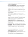
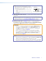
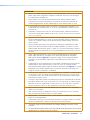
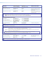
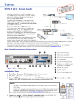
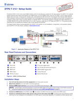
Application Diagram
The following diagram shows a typical application for a DTP2 T 203.
GRxTx
CONTACT IN RS-232TALLY OUT
123G 123+V
REMOTE
G
R
x
T
x
CO
NTA
C
T IN
RS
-232
T
ALLY
O
U
T
1
2
3
G
1
2
3
+
V
R
EM
O
TE
POWER
12V
1.5A MAX
INPUTS
AUDIO
1
HDMI
2
HDMI
DP
3
LINK
OUT
DTP
HDBT
OFF
SEND
POWER
SIG
OVER TP
REMOTE
LAN
Rx GTx RxTxG
RS-232 IR
RxTx
CONTACT IN RS-232
123G 123+V
TALLY OUT
OUTPUTS
POWER
12V
0.8A MAX
SIG LINK
DTP2 IN
RS-232
IR
Tx Rx Tx RxG
LR
AUDIO
OVER DTP2
1A 1B
DTP2/XTP/HDBT
2
DTP2/XTP
1A
1B
DTP2
/
XTP
/
HDBT
2
D
TP2
/
XTP
Tx Rx
RS-232
G
RESET
100-240V 50/60 Hz
--A MAX
IN1808 IPCP SA
Tx Rx
RTSCTS
G
Tx Rx GTxRxG
R
1234G
DIGITAL I/OCOM 3COM 2COM 1
SSGG
1
1
2
2
C34C
+S G-S+V
PWR OUT = 6W
RRRRRRRRRR
R
R
R
R
R
R
R
R
R
RR
R
R
IR/SERIALeBUSRELAYS
LANAV LAN 1
AV LAN 2
AV LAN 3
TLP Pro 1025M
IN1808 IPCP SA
DTP2 R 211
Projector
Extron
DTP2 T 203
Switcher
Ethernet
HDMI
PC
Blu-Ray
HDMI
Laptop
XTP DTP 24 Cable
330'
HDMI
DisplayPort to HDMI
Figure 1. Typical Application of the DTP2T 203
1

DTP2 T 203 • Installation 5
Installation
This section describes the installation and setup of the DTP2T 203 switcher. Topics include:
• Installation Overview
• Rear Panel Features
• Wiring Connections
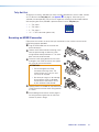
• Securing an HDMI Connector
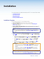
Installation Overview
To install and set up the DTP2T203 switching transmitter:
1. Turn off all equipment and disconnect from the power source.
2. Mount the switcher (optional) on a rack shelf or furniture (see Mounting the
DTP2T203 on page64).
3. Connect HDMI or DP input sources to one or more of the DTP2T 203 inputs. The
default (Extron) EDID is present at each input and Hot Plug Detect (HPD) is actively
controlled on each input.
NOTE: LockIt cable lacing brackets are provided to secure the HDMI cables to
the rear panel ports to reduce stress on the HDMI connectors and prevent signal
loss due to loose cable connections (see Securing an HDMI Connector on
page15).
4. Connect an RJ-45 DTP or HDBT receiving device to the output connector (see
figure2,
E
, on the next page). Set the DTP/HDBT switch (
F
) and SEND POWER
switch (
D
).
• If the receiving device is in the Extron DTP2 series, set the DTP/HDBT switch (
F
)
to DTP, and the SEND POWER switch (
D
) to the Up (SEND POWER) position.
• If the receiving device is in the Extron Legacy DTP series, set the DTP/HDBT
switch (
F
) to DTP, and the SEND POWER switch (
D
) to the Down (OFF)
position.
• If the receiving device is HDBaseT enabled, set the DTP/HDBT switch (
F
) to
HDBT, and the SEND POWER switch (
D
) to the Down (OFF) position.
ATTENTION:
• Position these switches (see figure2,
D
and
F
) BEFORE connecting the
appropriate device to the TP connector. Failure to comply can damage the
endpoint.
• Positionnez les sélecteur (voir figure2,
D
et
F
) AVANT de connecter
l’appareil approprié au connecteur TP. Ne pas respecter cette procédure
pourrait endommager le point de connexion.
NOTE: Use the provided LockIt cable lacing brackets to secure the HDMI cables to
the port to reduce stress on the HDMI connectors and prevent signal loss due to
loose cable connections (see Securing an HDMI Connector on page15).

DTP2 T 203 • Installation 6
5. Connect Over TP RS-232 and IR control. Connect a serial RS-232 signal, a
modulated IR signal, or both into this 3.5 mm, 5-pole captive screw port (see figure2,
G
) for IR and bidirectional RS-232 communication. 3.5mm, 3-pole captive screw
connectors (
C
) for IR transmission and bidirectional RS-232 communication (see Over
TP RS-232 and IR Control on page14 for wiring instructions).
6. Connect control devices. Connect your host computer to one of the following ports
to configure and control the switcher via SIS commands or PCS:
• LAN — Insert an RJ45 cable to the rear panel LAN port (
I
) for Ethernet
connectivity.
• Configuration port — Insert a USB mini-B connector into the front panel CONFIG
connector for USB control (see figure8,
C
, on page16.
7. Connect a contact closure device (optional). Connect a push-button contact closure
device to a Contact In port (see figure2,
H
, below) to enable input switching via
contact closure (see Contact In Port on page14 for wiring instructions).
8. Power on the devices connected to the output of the DTP2 T 203 switcher.
9. Connect power to the DTP T 203 switcher.
10. Configure the EDID (optional) (see EDID Minder on page28).
11. Power on the source devices.
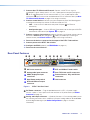
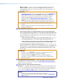
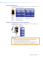
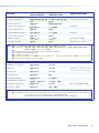
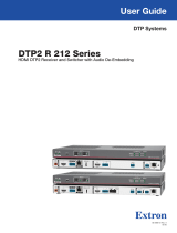
Rear Panel Features
DTP2 T 203
e
AUTO
SWITCH
R
CONFIG
1
MODE
2
NORMAL
3
AUTO
231
STAT US
SIGNAL
HDCP
POWER
12V
1.5A MAX
INPUTS
AUDIO
1
HDMI
2
HDMI
DP
3
LINK
OUT
DTP
HDBT
OFF
SEND
POWER
SIG
OVER TP
REMOTE
LAN
Rx GTx RxTxG
RS-232 IR
RxTx
CONTACT IN RS-232
123G 123+V
TALLY OUT
B
C
DA
H
BC
C
E
A
I
G
F
D
D
E
C
FD
A
DC Power connector
F
DTP and HDBaseT mode switch
B
Analog audio input connector
G
Over TP RS-232 and IR connectors
C
HDMI, DisplayPort input
connectors
H
Remote Contact, Tally, and RS-232
connectors
D
Send Power mode switch
I
LAN connector
E
DTP and HDBaseT output
connector
Figure 2. DTP2T203 Rear Panel
A
DC Power connector — Plug the provided external 12VDC, 2A power supply
into this 2-pole, 3.5mm captive screw inlet and into an AC power outlet (see Power
Connector on page10).
B
Analog audio input connector — (Optional) Connect a 3.5mm analog audio input to
the switching transmitter via this stereo mini jack port. Analog audio can be embedded
onto the digital video signal (see Audio Configuration on page22 for more
information).
2

DTP2 T 203 • Installation 7
NOTE: The analog audio input is in addition to the
digital audio that may be embedded in the HDMI
and DisplayPort inputs. The figure at right shows the
connector tip, ring, and sleeve.
• A mono audio connector consists of the tip and
sleeve.
• A stereo audio connector consists of the tip, ring,
and sleeve.
C
HDMI, DisplayPort input connectors — Connect HDMI or DisplayPort video sources
to these ports.
NOTE: Use provided LockIt cable lacing brackets to secure the HDMI cables to
the ports to reduce stress on the HDMI connectors and prevent signal loss due to
loose cable connections (see Securing an HDMI Connector on page5).
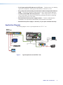
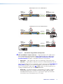
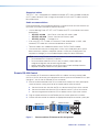
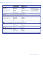
D
Send Power mode switch (see figure2 on page6— In a DTP2 transmitter to
DTP2 receiver configuration, set the toggle switch to the Up (Send Power) position on
the powered DTP2 unit to enable sending remote power to the far end. Set the toggle
switch to the Down (OFF) postion on the DTP2 unit receiving power.
ATTENTION:
• The DTP2T 203 device is configured to output power to DTP2 models only.
If connected to a non-DTP2 device, set the SEND POWER toggle switch
to the OFF (Down) position. Failure to turn the power OFF will damage the
connected non-DTP2 device (see figure3).
• Le DTP2T 203 est configuré pour fournir une alimentation aux modèles
DTP2 uniquement. S’il est connecté à un autre appareil, veuillez positionner
l’interrupteur à bascule sur « OFF » (Down). Si l’interrupteur n’est pas
positionné sur OFF, vous risquez d’entraîner la défaillance de l’appareil non
DTP2 connecté (voir figure3).
NOTES:
• When the output is configured for DTP mode, remote power is available only
if both the transmitter and the receiver are from the DTP2 series.
• When the output is configured for HDBT mode, remote power is not available
and both the transmitter and receiver require their own 12 VDC power supply.
Sleeve ( )
Ring (
-
)
Tip (+)
3.5 mm Stereo Plug Connector
(balanced)

DTP2 T 203 • Installation 8
DTP2 R 211
CONFIG
INPUT
LINK
OUTPUT
SEND
POWER
OFF
STATUS
SEND
POWER
OFF
SEND
POWER
OFF
DTP2 R 211
CONFIG
INPUT
LINK
OUTPUT
SEND
POWER
OFF
STATUS
SEND
POWER
OFF
SEND
POWER
OFF
SEND
POWER
OFF
DTP HDMI 330 Rx
OVER DTP
RS-232
IR
Tx Rx Tx RxG
OFF
OFF
ON
ON OFF
P
O
WER
O
FF
POWER
12V
1.5A MAX
INPUTS
AUDIO
1
HDMI
2
HDMI
DP
3
LINK
OUT
DTP
HDBT
OFF
SEND
POWER
SIG
OVER TP
REMOTE
LAN
Rx GTx RxTxG
RS-232 IR
RxTx
CONTACT IN RS-232
123G 123+V
TALLY OUT
P
O
WER
O
FF
POWER
12V
1.5A MAX
INPUTS
AUDIO
1
HDMI
2
HDMI
DP
3
LINK
OUT
DTP
HDBT
OFF
SEND
POWER
SIG
OVER TP
REMOTE
LAN
Rx GTx RxTxG
RS-232 IR
RxTx
CONTACT IN RS-232
123G 123+V
TALLY OUT
PO
WER
O
FF
POWER
12V
1.5A MAX
INPUTS
AUDIO
1
HDMI
2
HDMI
DP
3
LINK
OUT
DTP
HDBT
OFF
SEND
POWER
SIG
OVER TP
REMOTE
LAN
Rx GTx RxTxG
RS-232 IR
RxTx
CONTACT IN RS-232
123G 123+V
TALLY OUT
Local
Power Supply
CATx Cable
up to 330' (100 m)
Local
Power Supply
No Remote Power
Extron
DTP2 T 203
Transmitter
Extron
DTP HDMI 4K 330 Rx
Receiver
DTP2 Endpoint Connected to a DTP Endpoint
CATx Cable
up to 330' (100 m)
Direction of
Remote Power
Local
Power Supply
Extron
DTP2 T 203
Transmitter
Extron
DTP2 R 211
Receiver
CATx Cable
up to 330' (100 m)
Direction of
Remote Power
Extron
DTP2 T 203
Transmitter
Extron
DTP2 R 211
Receiver
DTP2 Endpoint Connected to a DTP2 Endpoint
Local
Power Supply
Figure 3. Send Power Toggle Switch Configuration
E
DTP and HDBaseT output connector — Plug one end of an STP cable into this
RJ-45 female output on the switcher. Plug the opposite end of this cable into the
DTP input on a compatible receiver (see Wiring the TP Connector and Cable
Recommendations on page12 to properly wire the RJ-45 connector).
• Signal LED — Lights green when the unit is outputting a TMDS clock signal.
• Link LED — Lights amber to indicate a valid link is established between the units.
The DTP and HDBaseT format is configured using SIS commands (see DTP/HDBaseT
Mode Switch on page52). If the receiving device is in the Extron DTP series, set
the DTP and HDBaseT mode switch (
F
) to DTP mode. If the receiving device is an
HDBaseT-enabled receiver type, set to HDBaseT mode.
• DTP mode — By default, the output is configured for DTP mode. It supports
remote powering of the DTP receiver, and transmits digital video and audio
and bidirectional IR control. The DTP2T203 transmits signals up to 330feet
(100meters) to any Extron device with a DTP output.
3

DTP2 T 203 • Installation 9
• HDBaseT mode — When the input is configured tor HDBaseT mode, remote
power is disabled. The DTP2T203 transmits digital video, IR control, and
embedded digital audio up to 330feet (100meters) to any third party device with
an HDBaseT output.
ATTENTION:
• Preconfigure remote power on the unit via SIS commands (see DTP2 Remote
Power Mode Switch on page52) BEFORE connecting the appropriate
device to the TP connector. Failure to comply can damage the endpoint.
• Configurez préalablement l’alimentation à distance sur l’unité via des
commandes SIS (voir DTP2 Remote Power Mode Switch à la page52)
AVANT de connecter l’appareil adapté au connecteur paires torsadées. Le
non-respect de cette procédure pourrait endommager le point de connexion.
• Do not connect this device to a telecommunications or computer data
network.
• Ne connectez pas cet appareil à un réseau de télécommunications ou de
données informatiques.
F
DTP and HDBaseT mode switch — Set this switch to DTP or HDBT according to the
receiving device connected to the switcher.
• If the receiving device is in the Extron DTP2 series or Legacy DTP series,
set this switch to the Down position to DTP. The output transmits HDMI digital video
with embedded audio, analog audio, RS-232 and IR, and remote power up to 330
feet (100 meters) to any Extron device with a DTP 330 input, or 230 feet (70 meters
to devices with a DTP 230 input.
• If the transmitter and receiver are from the Extron DTP2 series, they can
both be powered by one 12 VDC power supply connected to either unit.
• If the transmitter and receiver are not both from the Extron DTP2 series,
the transmitter and receiver each require its own 12 VDC power supply.
• If the receiving device is HDBaseT enabled receiver, set this switch to the UP
position to HDBT. The TP output transmits HDMI digital video with embedded audio
along with RS-232 and IR control up to 330 feet (100 meters) to any device with
an HDBaseT input. Both the transmitter and receiver each require its own 12VDC
power supply.
ATTENTION:
• Position this switch BEFORE connecting the appropriate device to the TP
connector. Failure to comply can damage the endpoint.
• Positionnez le sélecteur AVANT de connecter l’appareil approprié au
connecteur TP. Ne pas respecter cette procédure pourrait endommager le
point de connexion.
G
Over TP RS-232 and IR connectors — (Optional) Connect a serial RS-232 signal,
a modulated IR signal, or both into this 3.5 mm, 5-pole captive screw connector for
bidirectional RS-232 and IR communication (see Over TP RS-232 and IR Control on
page14 to wire the connector).
H
Remote Contact, Tally, and RS-232 connectors:
Contact In — If desired, for contact closure control plug a contact closure device into
this 3.5 mm, 4-pole captive screw port. Momentarily short the pin for the desired input
(1, 2, or 3) to G to select that input. To force an input to be always selected, leave the
short in place (see Contact In Port on page14 to wire the connector).
NOTES:
• Contact closure control overrides front panel input selections.
• For contact closure control, auto-switch mode must be off (see Selecting an
Input on page17).

DTP2 T 203 • Installation 10
Tally Out— If desired, to remotely identify the currently selected input plug a device into
this 3.5 mm, 4-pole captive screw connector. Connect the power wire for the device
into the +V pin and connected the ground wire for each indicator into the corresponding
Tally Out pin 1, 2, or 3. When an input is selected, by either contact closure or front
panel selection or SIS commands, the corresponding Tally Out pin shorts to ground,
closing the circuit and lighting the connected indicator (LED) (see Tally Out Port on
page15 to wire the connector).
RS-232— Plug a serial RS-232 device into this 3.5 mm, 3-pole captive screw
connector for remote control of the DTP2 T 203 (see Remote RS-232 Control on
page13 to wire the connector).
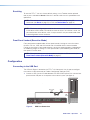
I
LAN connector — (Optional) for IP control of the system, connect the switcher to a
computer using a twisted pair cable, terminated with an RJ-45 connector. Through this
connection, a PC can control a connected device through a network (see Wiring the
LAN Connector on page12).
• Link LED indicator — Indicates the switcher is properly connected to an Ethernet
LAN. This green LED should light steadily.
• Activity LED indicator — Indicates transmission of data packets on the RJ-45
connector. This LED amber light should flicker as the switcher communicates.
Wiring Connections
Power Connector
A 12VDC, 2A power supply is provided with the DTP2T203. Follow these instructions to
wire the 2-pole captive screw connector to your power supply:
CAUTION: The DC output cables must be kept separate from each other while the
power supply is plugged in. Remove power before wiring.
ATTENTION : Les câbles de sortie CC doivent être séparés les uns des autres tant que
la source d’alimentation est branchée. Coupez l’alimentation avant d’effectuer tout
raccordement.
ATTENTION:
• Do not connect power to the DTP2 T 203 until you have read the ATTENTION
notices on the next page.
• Ne branchez pas l’alimentation au DTP2 T 203 avant d’avoir lu les mises en garde
«ATTENTION» en page suivante.
1. Cut the DC output cord to the length needed (see figure4 on the next page).
2. Strip the jacket to expose 3/16inch (5mm) of the conductors.
3. Slide the leads into the supplied 2-pole captive screw connector and secure them,
using a small screwdriver.
SECTION A–A
Ridges
Smooth
A
A
3/16"
(5 mm) Max.
POWER
12V
MAX
Figure 4. Wiring the Power Connector
4. To verify the power cord polarity before connecting the plug, connect the power supply
with no load and check the output with a voltmeter.
5. Use the supplied tie wrap to strap the power cord to the extended tail of the connector.
4

DTP2 T 203 • Installation 11
ATTENTION:
• Always use a power supply provided by or specified by Extron. Use of an unauthorized
power supply voids all regulatory compliance certification and may cause damage to
the supply and the end product.
• Utilisez toujours une source d’alimentation fournie ou recommandée par Extron.
L’utilisation d’une source d’alimentation non autorisée annule toute certification de
conformité réglementaire, et peut endommager la source d’alimentation et l’unité.
• If not provided with a power supply, this product is intended to be supplied by a UL
Listed power source marked “Class 2” or “LPS” and rated output 12 VDC, minimum
2A minimum.
• Si le produit n’est pas fourni avec une source d’alimentation, il doit être alimenté par
une source d’alimentation certifiée UL de classe 2 ou LPS, avec une tension nominale
12 Vcc, 2 A minimum.
• The installation must always be in accordance with the applicable provisions of National
Electrical Code ANSI/NFPA 70, article 725 and the Canadian Electrical Code part 1,
section 16. The power supply shall not be permanently fixed to building structure or
similar structure.
• Cette installation doit toujours être conforme aux dispositions applicables du Code
américain de l’électricité (National Electrical Code) ANSI/NFPA 70, article 725, et du
Code canadien de l’électricité, partie1, section16. La source d’alimentation ne devra
pas être fixée de façon permanente à la structure de bâtiment ou à d’autres structures
similaires.
• Power supply voltage polarity is critical. Incorrect voltage polarity can damage the
power supply and the unit. The ridges on the side of the cord identify the power
cord negative lead (see figure4 on the previous page). To verify the polarity before
connection, plug in the power supply with no load and check the output with a
voltmeter.
• La polarité de la source d’alimentation est primordiale. Une polarité incorrecte pourrait
endommager la source d’alimentation et l’unité. Les stries sur le côté du cordon
permettent de repérer le pôle négatif du cordon d’alimentation (voir figure4 sur la page
précédente). Pour vérifier la polarité avant la connexion, brancher l’alimentation hors
charge et mesurer sa sortie avec un voltmètre.
• The length of the exposed wires in the stripping process is important. The ideal length
is 3/16 inches (5 mm). Any longer and the exposed wires may touch, causing a short
circuit between them. Any shorter and the wires can be easily pulled out even if tightly
fastened by the captive screws.
• La longueur des câbles exposés est importante lorsque l’on entreprend de les dénuder.
La longueur idéale est de 5mm (3/16inches). S’ils sont trop longs, les câbles exposés
pourraient se toucher et provoquer un court-circuit. S’ils sont trop courts, ils peuvent
être tirés facilement, même s’ils sont correctement serrés par les borniers à vis.
• Unless otherwise stated, the AC/DC adapters are not suitable for use in air handling
spaces or in wall cavities.
• Sauf mention contraire, les adaptateurs CA/CC ne conviennent pas à une utilisation
dans les espaces d’aération ou dans les cavités murales.
• Remote power is intended for indoors use only. No part of a network that uses remote
power can be routed outdoors.
• L’alimentation à distance est exclusivement réservée à un usage en intérieur. Un réseau
utilisant une alimentation à distance ne peut pas être routé en extérieur.
• The power supply shall not be permanently fixed to building structure or similar
structure.
• La source d’alimentation ne devra pas être fixée de façon permanente à la structure
de bâtiment ou à d’autres structures similaires.
1 Attention

DTP2 T 203 • Installation 12
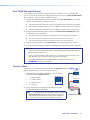
Wiring the LAN Connector
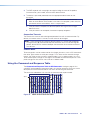
The crossover cable wiring standard is detailed in figure5. Use this standard to terminate
the LAN cable with the RJ-45 connector.
12345678
RJ-45
Connector
Insert T
wisted
Pair Wires
Pins:
A cable that is wired as TIA/EIA T568A at one
end and T568B at the other (Tx and Rx pairs
reversed) is a "crossover" cable.
A cable wired the same at both ends is called
a "straight-through" cable because no pin/pair
assignments are swapped.
T568B T568A T568B T568B
Straight-through Cable
(for connection to a switch, hub, or router)
End 1 End 2
Pin Wire Color Pin Wire Color
1 white-orange 1 white-orange
2 orange 2 orange
3 white-green 3 white-green
4 blue 4 blue
5 white-blue 5 white-blue
6 green 6 green
7 white-brown 7 white-brown
8 brown 8 brown
Crossover Cable
(for direct connection to a PC)
End 1 End 2
Pin Wire Color Pin Wire Color
1 white-orange 1 white-green
2 orange 2 green
3 white-green 3 white-orange
4 blue 4 blue
5 white-blue 5 white-blue
6 green 6 orange
7 white-brown 7 white-brown
8 brown 8 brown
Figure 5. LAN Cable Termination
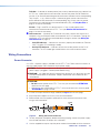
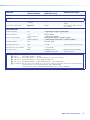
Wiring the TP Connector and Cable Recommendations
The TIA/EIA T 568B wiring standard is detailed in figure6. Use this standard to terminate
the TP cable with RJ-45 connectors.
5
Pin
1
2
3
6
7
8
4
Side
12345678
Insert
Twisted
Pair Wires
Pins:
RJ-45
Connector
Wire color
White-green
Green
White-orange
White-blue
Orange
White-brown
Brown
Blue
TIA/EIA T
568B
Figure 6. TP Cable Termination
ATTENTION:
• Do not use Extron UTP23SF-4 Enhanced Skew-Free AV UTP cable or STP201
cable to link the XTP products or with DTP transmitters or receivers. The
DTP2T203 does not work properly with these cables.
• N’utilisez pas le câble audiovisuel Skew-Free UTP version améliorée UTP23SF-4
Extron ou le câble STP201 pour relier les produits XTP à des émetteurs ou
récepteurs DTP. Le DTP2T203 ne fonctionne pas correctement avec ces câbles.
5
6
Page is loading ...
Page is loading ...
Page is loading ...
Page is loading ...
Page is loading ...
Page is loading ...
Page is loading ...
Page is loading ...
Page is loading ...
Page is loading ...
Page is loading ...
Page is loading ...
Page is loading ...
Page is loading ...
Page is loading ...
Page is loading ...
Page is loading ...
Page is loading ...
Page is loading ...
Page is loading ...
Page is loading ...
Page is loading ...
Page is loading ...
Page is loading ...
Page is loading ...
Page is loading ...
Page is loading ...
Page is loading ...
Page is loading ...
Page is loading ...
Page is loading ...
Page is loading ...
Page is loading ...
Page is loading ...
Page is loading ...
Page is loading ...
Page is loading ...
Page is loading ...
Page is loading ...
Page is loading ...
Page is loading ...
Page is loading ...
Page is loading ...
Page is loading ...
Page is loading ...
Page is loading ...
Page is loading ...
Page is loading ...
Page is loading ...
Page is loading ...
Page is loading ...
Page is loading ...
Page is loading ...
-
 1
1
-
 2
2
-
 3
3
-
 4
4
-
 5
5
-
 6
6
-
 7
7
-
 8
8
-
 9
9
-
 10
10
-
 11
11
-
 12
12
-
 13
13
-
 14
14
-
 15
15
-
 16
16
-
 17
17
-
 18
18
-
 19
19
-
 20
20
-
 21
21
-
 22
22
-
 23
23
-
 24
24
-
 25
25
-
 26
26
-
 27
27
-
 28
28
-
 29
29
-
 30
30
-
 31
31
-
 32
32
-
 33
33
-
 34
34
-
 35
35
-
 36
36
-
 37
37
-
 38
38
-
 39
39
-
 40
40
-
 41
41
-
 42
42
-
 43
43
-
 44
44
-
 45
45
-
 46
46
-
 47
47
-
 48
48
-
 49
49
-
 50
50
-
 51
51
-
 52
52
-
 53
53
-
 54
54
-
 55
55
-
 56
56
-
 57
57
-
 58
58
-
 59
59
-
 60
60
-
 61
61
-
 62
62
-
 63
63
-
 64
64
-
 65
65
-
 66
66
-
 67
67
-
 68
68
-
 69
69
-
 70
70
-
 71
71
-
 72
72
-
 73
73


Extron DTP2 T 203 User manual
- Category
- Video switches
- Type
- User manual
Ask a question and I''ll find the answer in the document
Finding information in a document is now easier with AI
Related papers
-
Extron DTP2 T 203 User manual
-
-
 Extron electronics DTP2 T 212 User manual
-
Extron DTP2 R 211 User manual
-
 Extron electronics DTP2 T 204 User manual
-
-
 Extron electronics DTP2 T 204 User manual
-
Extron DTP2 R 212 User manual
-
 Extron electronics DTP2 R 212 SA User manual
-
 Extron electronics DTP2 T 212 User manual


Other documents
-
ST Air Unit Operating instructions
-
SIIG CE-H23G11-S1 Quick start guide
-
Extron electronic DTP T USW 233 User manual
-
-
 Extron electronics DTP T SW4 HD 4K User manual
-
 Extron electronics DTP T MK 332 User manual
-
 Extron electronics DTP DVI 330 Tx Setup Manual
-
 Extron electronics XTP SR HDMI User manual
-
VigilLink VLPT-42H100 User manual
-


