Page is loading ...

Publication 1746-IN008A-US-P
Installation Instruction
SLC 500™ Analog I/O Modules
(Catalog Numbers 1746-NI4, -NIO4I, -NIO4V, -NO4I,
-NO4V, -FIO4I, and -FIO4V)
Inside… page
Important User Information ...................................................... 2
For More Information ............................................................... 3
Types of Analog Modules ......................................................... 4
Hazardous Location Considerations ......................................... 7
Environnements dangereux....................................................... 7
Choosing a Slot in the Chassis................................................ 10
Installing Your Module ........................................................... 11
Wiring Considerations............................................................. 13
Wiring the Analog Module...................................................... 15
Labeling and Installing the Terminal Block............................ 16
Minimizing Electrical Noise on Analog Modules .................. 17
Specifications.......................................................................... 22
Allen-Bradley HMIs

2 SLC 500™ Analog I/O Modules
Publication 1746-IN008A-US-P
Important User Information
Because of the variety of uses for the products described in this publication, those
responsible for the application and use of this control equipment must satisfy
themselves that all necessary steps have been taken to assure that each
application and use meets all performance and safety requirements, including any
applicable laws, regulations, codes and standards.
The illustrations, charts, sample programs and layout examples shown in this
guide are intended solely for purposes of example. Since there are many
variables and requirements associated with any particular installation,
Allen-Bradley does not assume responsibility or liability (to include intellectual
property liability) for actual use based upon the examples shown in this
publication.
Allen-Bradley publication SGI-1.1, Safety Guidelines for the Application,
Installation, and Maintenance of Solid-State Control (available from your local
Allen-Bradley office), describes some important differences between solid-state
equipment and electromechanical devices that should be taken into consideration
when applying products such as those described in this publication.
Reproduction of the contents of this copyrighted publication, in whole or in part,
without written permission of Allen-Bradley Company, Inc., is prohibited.
Throughout these installation instructions we use notes to make you aware of
safety considerations:
Attention statements help you to:
• identify a hazard
• avoid the hazard
• recognize the consequences
!
ATTENTION
Identifies information about practices or circumstances that
can lead to personal injury or death, property damage or
economic loss.
IMPORTANT
Identifies information that is critical for successful application
and understanding of the product.

SLC 500™ Analog I/O Modules 3
Publication 1746-IN008A-US-P
For More Information
As part of our effort to preserve, protect, and improve our environment,
Allen-Bradley is reducing the amount of paper we use. Less paper means more
options for you. In addition to traditional printed publications and CD-ROM
versions, we now offer on–line manuals with the most up-to-date information
you can get. We recommend that you read the related publications listed below
before starting up your control system.
Related Publications
If you would like a manual, you can:
• download a free electronic version from the internet:
www.theautomationbookstore.com
• purchase a printed manual by:
– contacting your local distributor or Rockwell Automation representative
– visiting www.theautomationbookstore.com
and placing your order
– calling 1.800.9NEWLIT (800.963.9548) (USA/Canada) or
001.330.725.1574 (Outside USA/Canada)
For Refer to this Document Pub. No.
A more detailed description on how to
configure the SLC 500 Analog I/O
Modules.
SLC 500 Analog I/O
Modules User Manual
1746-6.4
A more detailed description on how to
install and use your modular SLC 500
system.
SLC 500 Modular Hardware
Style Installation and
Operation Manual
1747-6.2
A reference manual that contains status file
data, instruction set, and troubleshooting
information.
SLC 500 and MicroLogix
1000 Instruction Set
Reference Manual
1747-6.15
A CD-ROM containing the three manuals
listed above, plus the:
• Discrete I/O Modules Installation
Instructions
• Discrete I/O Modules Product Data
SLC 500 Literature
Collection on CD-ROM
1747-CD1-1
Allen-Bradley HMIs

4 SLC 500™ Analog I/O Modules
Publication 1746-IN008A-US-P
Types of Analog Modules
1746-NI4 Analog Input Module
The NI4 Analog Input module contains 4 analog input channels that are user
selectable per channel for voltage or current to support a variety of monitoring
and controlling applications.
1746-NO4I and NO4V Analog Output Modules
The NO4I and NO4V Analog Output Modules provide 4 analog output channels.
The NO4I module contains four current outputs. The NO4V module contains
four voltage outputs. Both of these modules support a variety of monitoring and
controlling applications.
1746-NIO4I and NIO4V Analog Combination Modules
The NIO4I and NIO4V Analog Combination I/O modules provide two input and
two output channels in a single-slot module. The 1746-NIO4I module contains
two current or voltage inputs (user selectable per channel) and two current
outputs. The 1746-NIO4V module contains two current or voltage inputs (user
selectable per channel) and two voltage outputs.
1746-FIO4I and FIO4V Fast Analog Combination Modules
The FIO4I and FIO4V Fast Analog Combination modules are 2-input/2-output
combination modules ideal for high speed applications with more rapidly
changing analog signals. These fast response modules are best suited for control
of pressure and position in equipment such as hydraulic presses and molding
machines.
Analog Modules Operation
The module converts analog input signals to 16-bit binary values for storage in
the SLC processor’s input image table. The decimal range, number of significant
bits, and converter resolution depend on the input range that you use for the
channel.

SLC 500™ Analog I/O Modules 5
Publication 1746-IN008A-US-P
Analog Input A/D Characteristics
Analog Output D/A Characteristics
The analog modules have the same output characteristics.
Analog Module Hardware Features
The module contains a removable terminal block providing connection for the
analog input and/or output channels, which is specifically designed to interface
NI4, NIO4I, & NIO4V
Input Range
Decimal Range
(input image table)
Number of
Significant Bits
Nominal Resolution
±10V dc -1 LSB -32,768 to +32,767 16 305.176 mV/LSB
0 to 10V dc -1 LSB 0 to 32,767 15
0 to 5V dc 0 to 16,384 14
1 to 5V dc 3,277 to 16,384 13.67
±20 mA ±16,384 15 1.22070 mA/LSB
0 to 20 mA 0 to 16,384 14
4 to 20 mA 3,277 to 16,384 13.67
FIO4I and FIO4V
Input Range
Decimal Range
(input image table)
Number of
Significant Bits
Nominal Resolution
0 to 10V dc -1 LSB 0 to 4095 12 2.4414 mV/LSB
0 to 5V dc 0 to 2047 11
1 to 5V dc 409 to 2047 10.67
0 to 20 mA 0 to 2047 11 9.7656 µA/LSB
4 to 20 mA 409 to 2047 10.67
Module Output Range Decimal Range
(output image
table)
Significant
Bits
Resolution
FIO4I
NIO4I
NO4I
0 to 21 mA - 1
LSB
0 to 32,764 13 bits 2.56348 µA/LSB
0 to 20 mA 0 to 31,208 12.92 bits
4 to 20 mA 6,242 to 31,2089 12.6 bits
FIO4V
NIO4V
NO4V
±10V dc - 1 LSB -32,768 to +32,764 14 bits 1.22070 mV/LSB
0 to 10V dc -1
LSB
0 to 32,764 13 bits
0 to 5V dc 0 to 16,384 12 bits
1 to 5V dc 3,277 to 16,384 11.67 bits
Allen-Bradley HMIs

6 SLC 500™ Analog I/O Modules
Publication 1746-IN008A-US-P
with analog current and voltage input signals. The channels can be wired as
either single-ended or differential inputs. There are DIP switches on the circuit
board for selecting voltage or current input.
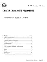
Hardware Feature Function
Function Label Indicates input, output, or both.
Power Status LED Indicates when backplane power is applied to the module.
Removable Terminal
Block
Provides physical connection to input devices.
Door Label Permits easy terminal identification.
Door Protects terminal connections and label.
(5) ANL COM
(6) NOT USED
(7) OUT 0
(8) ANL COM
(9) NOT USED
(10) OUT 1
(11)ANL COM
ANALOG
POWER
OUTPUT INPUT
(4) IN 1±
(3) IN 1+
(2) ANL COM
(1) IN 0±
(1) IN 0+
Power Status LED
Door Label
Door
Removable Terminal
Function Label

SLC 500™ Analog I/O Modules 7
Publication 1746-IN008A-US-P
Hazardous Location Considerations
This equipment is suitable for use in Class I, Division 2, Groups A, B, C, D or
non-hazardous locations only. The following WARNING statement applies to
use in hazardous locations.
Environnements dangereux
Cet équipement est conçu pour être utilisé dans des environnements de Classe 1,
Division 2, Groupes A, B, C, D ou non dangereux. La mise en garde suivante
s’applique à une utilisation dans des environnements dangereux.
!
WARNING
EXPLOSION HAZARD
• Substitution of components may impair suitability for Class
I, Division 2.
• Do not replace components or disconnect equipment unless
power has been switched off.
• Do not connect or disconnect components unless power has
been switched off.
• All wiring must comply with N.E.C. article 501-4(b).
MISE EN
!
DANGER D’EXPLOSION
• La substitution de composants peut rendre cet
équipement impropre à une utilisation en environnement
de Classe 1, Division 2.
• Ne pas remplacer de composants ou déconnecter
l'équipement sans s'être assuré que l'alimentation est
coupée.
• Ne pas connecter ou déconnecter des composants sans
s'être assuré que l'alimentation est coupée.
Allen-Bradley HMIs

8 SLC 500™ Analog I/O Modules
Publication 1746-IN008A-US-P
Determining Your Power Requirements for a Modular
Controller
Analog modules require both 5V dc and 24V dc power from the backplane of the
SLC 500 system. However, the NO4I and NO4V analog modules can use an
external 24V dc power supply. This eliminates the 24V dc backplane power
requirements, providing configuration flexibility if SLC power supply loading is
critical. These two modules provide user-supplied external 24V dc power supply
connections.
The following table shows the power requirements for each analog module using
backplane power. Use this table to calculate the total load on the modular system
power supply. For more information refer to the SLC 500 Modular Hardware
Style Installation and Operation Manual, publication 1747-6.2.
IMPORTANT
The analog modules do not supply loop power for the input
device. You must supply the appropriate loop power for
loop-powered input devices.
Catalog Number 5 Volt Current 24 Volt Current
1746-NI4 35 mA 85 mA
1746-NIO4I 55 mA 145 mA
1746-NIO4V 55 mA 115 mA
1746-NO4I 55 mA
195 mA
(1)
(2)
(1) The 24V dc user power connection on a fixed SLC 500 can power an NO4I or NO4V analog
module. However, the regulation of the 24V dc user connection on a modular SLC 500 power
supply, catalog number 1746-P1, -P2, and -P4 is outside of the requirements of the NO4I and
NO4V analog modules and cannot be used.
(2) Omit these values from your SLC power supply loading calculations if you decide to use an
external power supply.
1746-NO4V 55 mA
145 mA
(1)
(2)
1746-FIO4I 55 mA 150 mA
1746-FIO4V 55 mA 120 mA

SLC 500™ Analog I/O Modules 9
Publication 1746-IN008A-US-P
Determining Your Power Requirements for a Fixed
Controller
Configuring Your Module
The NI4, NIO4I, NIO4V, FIO4I, and FIO4V analog modules have
user-selectable DIP switch settings, which allow you to configure the input
channels as either current or voltage inputs. The switches are located on the
analog module board. The following illustration shows the ON and OFF switch
settings. Switch orientation is also provided on the nameplate of the module.
Switch Settings for the 1746-NI4
The NI4 has 4 individual DIP switches that control the input mode of channels 0
through 3. A switch in the ON position configures the channel for current input.
A switch in the OFF position configures the channel for voltage input.
IMPORTANT
The 2-slot, SLC 500 fixed I/O expansion chassis (1746-A2)
will support only specific combinations of modules. If you
wish to use an I/O module in a 2-slot expansion chassis with
another SLC I/O or communication module, refer to the SLC
500 Analog I/O Modules User Manual, publication 1746-6.4
for valid combinations of modules.
!
ATTENTION
Care should be taken to avoid connecting a voltage source to a
channel configured for current input. Improper module
operation or damage to the module can occur.
ON - Configures channel for current input
OFF - Configures channel for voltage input
Switch 1 = Channel 0
Switch 2 = Channel 1
Switch 3 = Channel 2
Switch 4 = Channel 3
1
2
3
4
N
O
Current
Vol ta ge
Allen-Bradley HMIs

10 SLC 500™ Analog I/O Modules
Publication 1746-IN008A-US-P
Switch Settings for the 1746-NIO4I, -NIO4V, -FIO4I, and
-FIO4V
The NIO4I and NIO4V have 2 individual switches labeled 1 and 2. These
switches control the input mode of channel 0 and 1. A switch in the ON position
configures the channel for current input. A switch in the OFF position configures
the channel for voltage input.
External Power Switch for the 1746-NO4I and -NO4V
The NO4I and NO4V analog output modules have an external 24V dc power
switch, SW1, which gives you the option of using an external power supply. In
the UP position, power is drawn from an external power source. In the DOWN
position, power is drawn from the backplane of the module. The switch is located
on the analog module board. Switch orientation is also provided on the nameplate
of the module.
Choosing a Slot in the Chassis
Two factors determine where the analog module should be located in the chassis:
ambient temperature and electrical noise. Consider the following conditions
when selecting a slot for an analog module. Position the module:
• in a slot away from an ac or high voltage dc modules
• in the chassis closest to the bottom of the enclosure where the SLC 500 system
is installed
• away from the chassis power supply if installed in a modular system
Switch 1 = Channel 0
Switch 2 = Channel 1
12
N
O
Current
Vo lt ag e
External
Backplane
24V dc
Power
Selector
SW1

SLC 500™ Analog I/O Modules 11
Publication 1746-IN008A-US-P
Installing Your Module
All modules are mounted in a single slot. Remember that in a modular system the
processor always occupies the first slot of the first chassis.
1. Verify that all switches are set correctly for the application.
2. Align the circuit board of the analog module with the card guide of the chassis
as shown below.
3. Slide the module in until both top and bottom retaining clips are secured.
4. To remove the module, depress the retaining clips at the top and bottom of the
module and slide the module out.
!
ATTENTION
Never install, remove, or wire modules with power applied to
the chassis. Also, do not expose analog modules to surfaces or
other areas that may typically hold an electrostatic charge.
Electrostatic charges can destroy the analog circuitry.
IMPORTANT
The potentiometer sets the voltage during factory calibration
to 2.5 volts. It is set and sealed at the factory and does not
require any adjustments.
!
ATTENTION
Care should be taken to avoid connecting a voltage source to a
channel configured for a current input. Improper module
operation or damage to the module can occur.
Allen-Bradley HMIs

12 SLC 500™ Analog I/O Modules
Publication 1746-IN008A-US-P
Top and Bottom
Module Release (s)
Card
Guide

SLC 500™ Analog I/O Modules 13
Publication 1746-IN008A-US-P
Wiring Considerations
The following section provides system wiring guidelines, how to ground your
Belden™ cable, and how to determine the cable length.
System Wiring Guidelines
Use the following guidelines in planning the system wiring for the analog
modules:
• all analog common terminals (ANL COM) are electrically connected inside
the module. ANL COM is not connected to earth ground inside the module.
• voltages on IN+ and IN- terminals must remain within ± 20 Volts with respect
to ANL COM to ensure proper input channel operation. This is true for current
and voltage input channel operation.
• voltage outputs (OUT 0 and OUT 1) of the NIO4V and NO4V are referenced
to ANL COM. Load resistance (R1) for a voltage output channel must be
greater than or equal to 1K ohms.
• current output channels (OUT 0 and OUT 1) of the NIO4I and NO4I source
current that returns to ANL COM. Load resistance (R1) for a current output
channel must remain between 0 and 500 ohms.
After the analog input module is properly installed in the chassis, follow the
wiring procedure below using Belden 8761 cable.
!
ATTENTION
Before wiring any analog module, disconnect power from the
SLC 500 system and from any other source to the analog
module.
!
ATTENTION
Care should be taken to avoid connecting a voltage source to a
channel configured for current input. Improper module
operation or damage to the voltage source can occur.
Allen-Bradley HMIs

14 SLC 500™ Analog I/O Modules
Publication 1746-IN008A-US-P
Grounding Your Cable
Belden cable #8761 has two signal wires (black and clear), one drain wire and a
foil shield. Refer to illustration below for Belden cable #8761. The drain wire
and foil shield must be grounded at one end of the cable. Do not earth ground the
drain wire and foil shield at both ends of the cable.
Input Channel - Use a chassis mounting tab as a ground for the drain wire and
foil shield.
Output Channel - Ground the drain wire and foil shield at the analog load.
Determining the Cable Length
Determine the length of cable you will need to connect a channel to its input or
output device. Remember to leave additional length to route the drain wire and
foil shield for earth grounding.
IMPORTANT
If you cannot ground the output channel at the load, ground the
drain wire and foil shield at the chassis mounting tab. Do not
connect the foil shield or drain wire to the analog terminal
block. They must be connected to an earth ground, which is
not provided at the analog module.
Belden Cable #8761
Foil Shield
Black Wire
Drain Wire
Clear Wire

SLC 500™ Analog I/O Modules 15
Publication 1746-IN008A-US-P
Wiring the Analog Module
After the analog module is properly installed in the chassis, use the following
wiring procedure. Belden cable #8761 is recommended when wiring analog
modules. This section assumes that you have properly installed the analog
module.
To wire your analog module, follow these steps and refer to the illustrations on
page 14.
1. Designate the end of the cable where the drain wire and foil shield is earth
grounded as END 1. Designate the other end as END 2.
2. At each end of the cable, strip some casing to expose the individual wires.
3. Trim the signal wires to 50 mm (2 inch) lengths. Strip 5 mm (about 3/16 inch)
of insulation away to expose the end of the wire.
4. At END 1, twist the drain wire and foil shield together, bend them away from
the cable, and apply shrink wrap.
5. At END 2, cut the drain wire and foil shield back to the cable and apply shrink
wrap.
6. Connect the signal wires (black and clear) to the terminal block and the input
and output devices. The recommended maximum torque is 0.57 Nm (5 lb-in)
for all terminals.
• Input channels - connect END 1 at module. Use a chassis mounting tab
as a ground for the drain wire and foil shield.
• Output channel- connect END 2 at the module. Ground the drain wire
and foil shield at the analog load.
7. Repeat steps 1 through 6 for each channel on the analog module. Jumper the
unused plus (+), minus (-) and common terminals of each input channel
individually. Unused output and common terminals should be left
unconnected.
The following illustrations depict the proper cable preparation for END 1 and
END 2. Shrink wrap is applied to each cable end. Make sure the foil shield and
drain wires on END 1 are long enough to reach their designated earth ground
points.
!
ATTENTION
Before wiring any analog module, disconnect power from the
SLC 500 system and from any other source to the analog
module.
Allen-Bradley HMIs

16 SLC 500™ Analog I/O Modules
Publication 1746-IN008A-US-P
Labeling and Installing the Terminal Block
The terminal block has a write-on label. Labeling the terminal block will help
ensure that it is installed on the correct module.
When installing the analog module in a chassis, it is not necessary to remove the
terminal block from the module. However, if the terminal block is removed, use
the write–on label located on the side of the terminal block to identify the module
location and type.
NOTE
The black dot on the terminal block label indicates the position
of terminal 0.
Cable Preparation END 1
Foil Shield and
Drain Wire
Black Wire
Black Wire
Clear Wire
Clear Wire
Insulation
Insulation
Cable Preparation END 2
SLOT ____
RACK ____
MODULE _____
Terminal Block

SLC 500™ Analog I/O Modules 17
Publication 1746-IN008A-US-P
Once you have wired your analog module and properly labeled the terminal
block, install the terminal block on the analog module. To install the terminal
block:
1. Align the terminal block with the receptacle.
2. Insert the terminal block and press firmly at the top and bottom until it is
properly secured.
To remove the terminal block, grasp it on the top and bottom and pull outward
and down.
Minimizing Electrical Noise on Analog
Modules
Inputs on analog modules employ digital high frequency filters that significantly
reduce the effects of electrical noise on input signals. However, because of the
variety of applications and environments where analog modules are installed and
operating, it is impossible to ensure that all environmental noise will be removed
by the input filters.
Although it is not the purpose of this installation instruction to address SLC 500
system procedures, several specific steps can be taken to help reduce the effects
of environmental noise on analog signals:
• Install the SLC 500 system in a properly rated (i.e., NEMA) enclosure. Make
sure that the SLC 500 system is properly grounded.
• Use Belden cable #8761 for wiring the analog modules making sure that the
drain wire and foil shield are properly earth grounded.
• Route the Belden cable separate from any other wiring. Additional noise
immunity can be obtained by routing the cables in grounded conduit.
• Group analog and low voltage dc modules away from ac I/O or high voltage
dc modules.
Allen-Bradley HMIs

18 SLC 500™ Analog I/O Modules
Publication 1746-IN008A-US-P
A system may malfunction due to a change in the operating environment after a
period of time. We recommend periodically checking system operation,
particularly when new machinery or other noise sources are installed near the
SLC 500 system. For further details on system installation and start-up refer to:
• SLC 500 Modular Hardware Style Installation and Operation Manual,
publication 1747-6.2
• SLC 500 Fixed Hardware Style Installation and Operation Manual,
publication 1747-6.21
• Safety Guidelines for the Application, Installation Maintenance of Solid State
Control, publication SGI-1.1.

SLC 500™ Analog I/O Modules 19
Publication 1746-IN008A-US-P
Wiring Diagram (showing differential inputs)
0
1
2
9
10
11
+
-
+
-
3
4
5
6
7
8
0
1
2
9
10
11
3
4
5
6
7
8
0
1
2
3
4
5
6
7
0
1
+
-
NI4
analog
source
analog
source
analog
source
earth
ground
earth
ground
Jumper
unused
inputs.
IN 0+
IN 0-
ANL COM
IN 1+
IN 1-
ANL COM
IN 2+
IN 2-
ANL COM
IN 3+
IN 3-
ANL COM
IN 0+
IN 0-
ANL COM
IN 1+
IN 1-
ANL COM
IN 2+
IN 2-
ANL COM
IN 3+
IN 3-
ANL COM
earth
ground
Jumper
unused
inputs.
LOAD
earth
ground
NIO4I, NIO4V,
FIO4I, and FIO4V
Do not
jumper
NO4I and NO4V
24V dc power supply if external
power is selected. Cable length from
external 24V dc power supply to
analog module must be less than
Ext. pwr
sup.
+24V dc
dc COM
LOAD
LOAD
earth
ground
earth
ground
Do not jumper
unused outputs.
OUT 0
ANL COM
OUT 1
ANL COM
OUT 2
ANL COM
OUT 3
ANL COM
Analog commons are internally
connected in the module.
Channels are not isolated from
Allen-Bradley HMIs

20 SLC 500™ Analog I/O Modules
Publication 1746-IN008A-US-P
Wiring Schematics for 2, 3, and 4-Wire Analog Input
Devices
IMPORTANT
The module does not provide loop power for analog inputs.
Use a power supply that matches the transmitter
specifications.
+-
+
-
+
-
+
-
+
-
+
-
2-Wire Transmitter
Transmitter
Transmitter
Transmitte
Module
IN +
IN -
ANL
Power
Supply
Power
Supply
Power
Supply
Supply Signal
GND
Supply Signal
Module
IN +
IN -
ANL
Module
IN +
IN -
ANL
3-Wire Transmitter
4-Wire Transmitter
/