Page is loading ...

Installation Instructions
SLC 500™ Fixed Hardware Style
Controllers
(Catalog Numbers 1747-L20, 1747-L30, and 1747-L40)
Inside… page
English Section....................................................................................... 3
Section en français............................................................................... 23
Deutscher Abschnitt............................................................................. 43
Sezione italiana.................................................................................... 63
Sección en español............................................................................... 83
Physical Dimensions........................................................................... 103
Wiring Diagrams................................................................................. 104
AB Drives

Publication 1747-IN008B-MU-P
Installation Instructions
English Section
SLC 500™ Fixed Hardware Style
Controllers
(Catalog Numbers 1747-L20, 1747-L30, and 1747-L40)
Inside… page
Important User Information .................................................................... 4
For More Information.............................................................................. 5
Safety Considerations............................................................................. 6
Controller Spacing .................................................................................. 7
Mounting the 2-Slot Expansion Chassis (Optional)................................ 7
Mounting Your Controller ....................................................................... 8
Configuring the High-Speed Counter...................................................... 9
Grounding Your Controller .................................................................... 10
Wiring Your Controller .......................................................................... 11
Understanding LED Messages.............................................................. 12
Configuration Options........................................................................... 15
Specifications ....................................................................................... 16
Using Surge Suppressors...................................................................... 19
Physical Dimensions ........................................................................... 103
Wiring Diagrams................................................................................. 104
AB Drives

4 SLC 500™ Fixed Hardware Style Controllers
Publication 1747-IN008B-MU-P
Important User Information
Because of the variety of uses for the products described in this publication, those
responsible for the application and use of this control equipment must satisfy
themselves that all necessary steps have been taken to assure that each application
and use meets all performance and safety requirements, including any applicable
laws, regulations, codes, and standards.
The illustrations, charts, sample programs, and layout examples shown in this guide
are intended solely for purposes of example. Since there are many variables and
requirements associated with any particular installation, Allen-Bradley does not
assume responsibility or liability (to include intellectual property liability) for actual
use based upon the examples shown in this publication.
Allen-Bradley publication SGI-1.1, Safety Guidelines for the Application, Installation,
and Maintenance of Solid-State Control (available from your local Allen-Bradley
office), describes some important differences between solid-state equipment and
electromechanical devices that should be taken into consideration when applying
products such as those described in this publication.
Reproduction of the contents of this publication, in whole or in part, without
written permission of the Allen-Bradley Company is prohibited.
Throughout these installation instructions we use notes to make you aware of safety
considerations:
Attention statements help you to:
•identify a hazard
•avoid the hazard
• recognize the consequences
!
ATTENTION
Identifies information about practices or circumstances that can
lead to personal injury or death, property damage, or economic
loss.
IMPORTANT
Identifies information that is critical for successful application
and understanding of the product.

SLC 500™ Fixed Hardware Style Controllers 5
Publication 1747-IN008B-MU-P
For More Information
As part of our effort to preserve, protect, and improve our environment,
Allen-Bradley is reducing the amount of paper we use. Less paper means more
options for you. In addition to traditional printed publications and CD-ROM
versions, we now offer on-line manuals with the most up-to-date information
available. We recommend that you read the related publications listed below before
starting up your control system.
Related Publications
If you would like a manual, you can:
• download a free electronic version from the internet at
www.theautomationbookstore.com
• purchase a printed manual by:
– contacting your local distributor or Rockwell Automation representative
– visiting www.theautomationbookstore.com and placing your order
– calling 1.800.963.9548 (USA/Canada or 001.330.725.1574 (Outside
USA/Canada)
For Refer to this Document Pub. No.
A more detailed description on how to install
and use your fixed SLC 500 system.
SLC 500 Fixed Hardware
Style Installation and
Operation Manual
1747-6.21
A reference manual that contains status file
data, instruction set, and troubleshooting
information.
SLC 500 and MicroLogix
1000 Instruction Set
Reference Manual
1747-6.15
A CD-ROM containing both of the manuals
listed above, plus the:
• SLC 500 Modular Hardware Style
Installation and Operation Manual
• SLC 500 Analog I/O Modules User Manual
• Discrete I/O Modules Installation
Instructions
• Discrete I/O Modules Product Data
SLC 500 Literature
Collection on CD-ROM
1747-CD1-1
AB Drives

6 SLC 500™ Fixed Hardware Style Controllers
Publication 1747-IN008B-MU-P
Safety Considerations
High Voltages -
SLC 500 Fixed Hardware Style Controller (Series C)
(Applies to 1747-L20A, -L30A, -L40A, -L20C, -L30C, and -L40C
controllers)
For general recommendations concerning installation safety requirements and safety
related work practices, refer to the requirements specific to your region.
• Europe: Reference the standards found in EN 60204 and your national
regulations.
• United States: Refer to NFPA 70E, Electrical Safety Requirements for Employee
Workplaces.
!
ATTENTION
The printed circuit board, located under the front cover of Series
C fixed hardware style controllers, has high voltages (120V ac
and 240V ac) available at certain points when the controller is
powered up. If the front cover is removed, exercise extreme care
and consider all points on the circuit board to be electrically
hazardous. Whenever possible, turn off power to the controller
before removing the cover.
Do not remove the protective insulation covering the circuit
board. If the insulation is missing, do not touch any portion of
the circuit board. Failure to heed this warning may result in
personal injury or death.
Front Cover

SLC 500™ Fixed Hardware Style Controllers 7
Publication 1747-IN008B-MU-P
Controller Spacing
Follow the recommended controller orientation and minimum spacing shown below
to allow for convection cooling within the enclosure. Air in the enclosure must be
kept within the range of 0°C to +60°C (+32°F to +140°F).
Mounting the 2-Slot Expansion Chassis (Optional)
The expansion chassis mounts on the right side of the fixed controller.
1. Align the mounting inserts of the expansion chassis with the mounting slots of
the controller. Slide the expansion chassis forward until the back of the expansion
chassis is flush with the fixed controller and the connector on the expansion
circuit board is mated with the connector in the controller.
A
B
A
B
TOP
SIDESIDE
BOTTOM
A. Greater than 101.6 mm (4 in.)
B. Greater than 152.4 mm (6 in.)
Enclosure
AB Drives

8 SLC 500™ Fixed Hardware Style Controllers
Publication 1747-IN008B-MU-P
2. To install additional I/O and specialty I/O modules, gently slide the module in
until the top and bottom retainer clips are secured.
Mounting Your Controller
You can mount the fixed hardware style unit directly to the back panel of your
enclosure using the mounting tabs and #10 and #12 screws. The maximum torque
requirement is 3.4 N-m (30 in-lbs).
To install your controller using mounting screws:
1. Position your controller on the mounting
surface. (Make sure the controller is spaced
properly. See page 7 for further information.)
2. Mark the positions of the mounting tabs and
drill the appropriate holes.
3. Mount your controller.
!
ATTENTION
Be careful of metal chips when drilling mounting holes for your
controller. Metal chips or clippings may short circuit electronic
components of the controller and cause damage.
Capacitors on input modules have a stored charge that can cause
a non-lethal shock. Avoid mounting the controller in a position
where installation or service personnel would be in danger from a
startle reaction.
Retainer clip
Mounting Tabs

SLC 500™ Fixed Hardware Style Controllers 9
Publication 1747-IN008B-MU-P
Configuring the High-Speed Counter
The fixed controllers that have 24V dc input circuits are also equipped with a
high-speed counter. For high-speed counter use, follow the procedure below:
1. Turn off power to the fixed controller.
2. Remove the SLC 500 cover.
3. Locate and cut jumper wire J2. The jumper is either beneath or to the right of the
battery connector. Do not remove the jumper wire completely, but make certain
that the ends of the cut jumper wire are not touching each other.
!
ATTENTION
When power is applied to the controller, hazardous electrical
potentials exist under the front cover. See page 6 for further
information.
J2
J2
Power
Fuse
The High-Speed Counter jumper is located either beneath the battery connector OR to
the right of the battery connector.
AB Drives

10 SLC 500™ Fixed Hardware Style Controllers
Publication 1747-IN008B-MU-P
Grounding Your Controller
In solid-state control systems, grounding helps limit the effects of noise due to
electromagnetic interference (EMI). Run the ground connection from the ground
screw of the controller (first screw from the left on the lower input terminal rung) to
the ground bus.
You must also provide an acceptable grounding path for each device in your
application. Exact connections will differ between applications. For more
information on proper grounding guidelines, refer to Industrial Automation Wiring
and Grounding Guidelines, Publication Number 1770-4.1 or the requirements
specific to your region:
• Europe: Reference the standards found in EN 60204 and your national
regulations.
• United States: Refer to NFPA 70E, Electrical Safety Requirements for Employee
Workplaces.
!
ATTENTION
The SLC 500 controller, other control devices, and the enclosure
must be properly grounded. All applicable codes and ordinances
must be observed when wiring the controller system.
SLC 500 Controller Only
#14 AWG
Wire
#10 AWG
Wire
#8 AWG
Wire
#8 AWG
Wire
#10 AWG
Wire
#14 AWG
Wire
SLC 500 Controller with 2-Slot Expansion Chassis
Chassis Mounting Tabs
Chassis Mounting Tabs
Earth
Ground
Earth
Ground
Ground
Bus
Ground
Bus

SLC 500™ Fixed Hardware Style Controllers 11
Publication 1747-IN008B-MU-P
Wiring Your Controller
See page 104 to locate the wiring diagram for your controller.
Use acceptable wire gauge
Use acceptable wire gaugeUse acceptable wire gauge
Use acceptable wire gauge - The I/O wiring terminals are designed to accept #14
or smaller AWG stranded wires, and two wires per terminal (maximum). Maximum
torque 0.9 N-m (8 in-lb.).
Label wires
Label wiresLabel wires
Label wires - Label wiring to I/O devices, power sources, and ground. Use tape,
shrink-tubing, or other dependable means for labeling purposes. In addition to
labeling, use colored insulation to identify wiring based on signal characteristics. For
example, you may use blue for dc I/O wiring and red for ac I/O wiring.
Bundle wires
Bundle wiresBundle wires
Bundle wires - Bundle wiring for each similar I/O device together. If you use ducts,
allow at least 5 cm (2 in.) between the ducts and the controller so there is sufficient
room to wire the devices.
Identify terminals
dentify terminals dentify terminals
dentify terminals - Terminal cover plates have a write-on area for each terminal.
Use this area to identify your I/O devices. Label the Removable Terminal Block
(RTB) with appropriate slot, rack (chassis) and module identification if you have not
already.
Power
PowerPower
Power - The fixed controllers are equipped with an auto-ranging power supply. This
means that you can connect either 120V ac or 240V ac to the controller, and the
controller power supply will automatically configure itself to operate with the
applied voltage.
!
ATTENTION
Before you install and wire I/O devices, disconnect power from
the controller and any other source to the I/O devices.
!
ATTENTION Calculate the maximum possible current in each power and
common wire. Observe all local electrical codes dictating the
maximum current allowable for each wire size. Current above the
maximum ratings may cause wiring to overheat, which can cause
damage.
AB Drives

12 SLC 500™ Fixed Hardware Style Controllers
Publication 1747-IN008B-MU-P
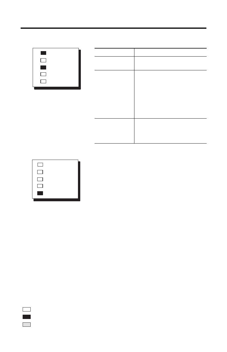
Understanding LED Messages
Identifying Fixed Controller LED Messages
1. Apply power to your controller.
2. Match your controller LEDs with the LEDs located to the left of each table.
3. Move across the table to identify the probable cause.
4. Follow the recommended action steps for each probable cause until the cause is
identified. If recommended actions do not identify the cause, contact your local
Allen-Bradley sales office or distributor.
!
ATTENTION
Have all personnel remain clear of the controller and equipment
when power is applied. Have someone ready to operate an
emergency-stop switch in case it becomes necessary to shut off
power to the controller equipment. Also, see NFPA 70E Part II
for additional guidelines for safety related work practices.
Never reach into a machine to actuate a switch since unexpected
machine motion can occur and cause injury.
Probable Cause Recommended Action
Initial CPU Factory
Power-up Condition
1. Follow the start-up procedures in
the
Fixed Hardware style
Controllers Installation and
Operation Manual
, Publication
1747-6.21.
2. Download a ladder logic program
to clear the CPU FAULT LED.
POWER
PC RUN
CPU FAULT
FORCED I/O
BATTERY LOW
Indicates the LED is off.
Indicates the LED is on.
Indicates the LED is flashing
Refer to the following key to determine the status of the LED indicators:

SLC 500™ Fixed Hardware Style Controllers 13
Publication 1747-IN008B-MU-P
Probable Cause Recommended Action
No Line Power Verify proper line voltage and
connections on the power terminals.
Power Supply
Fuse Blown
1. Check for the proper incoming
power connections.
2. Check the incoming power fuse.
Replace the fuse. (See page 9 for
fuse location) If fuse blows again,
replace the fixed controller.
Power Supply
Overloaded
This problem can occur intermittently if
power supply is lightly overloaded
when output loading and temperature
varies. If you are using a 2-slot chassis,
verify the compatibility of the modules
to prevent overloading the backplane
power.
POWER
PC RUN
CPU FAULT
FORCED I/O
BATTERY LOW
Error Type:
Inadequate
System Power
Indicates the LED is off.
Indicates the LED is on.
Indicates the LED is flashing
Refer to the following key to determine the status of the LED indicators:
AB Drives
14 SLC 500™ Fixed Hardware Style Controllers
Publication 1747-IN008B-MU-P
Regardless of any other LED status indicator
conditions, always replace the battery when the
BATTERY LOW LED is on if you want RAM
battery backup.
Probable Cause Recommended Action
CPU Memory Error
or Faulty CPU
Cycle power. If the steady CPU FAULT
LED reappears, replace the controller.
Faulty Memory
Module
1. Remove power and then remove
the memory module from the
controller.
2. Re-energize the controller.
If steady CPU FAULT LED changes to
flashing, replace the existing memory
module with a replacement module.
Processor Firmware
Installed Incorrectly
If upgrading the processor to a
different firmware level, verify that
the firmware chip orientation
matches the upgrade kit directions.
POWER
PC RUN
CPU FAULT
FORCED I/O
BATTERY LOW
Error Type:
CPU Fault
POWER
PC RUN
CPU FAULT
FORCED I/O
BATTERY LOW
Indicates the LED is off.
Indicates the LED is on.
Indicates the LED is flashing
Refer to the following key to determine the status of the LED indicators:

SLC 500™ Fixed Hardware Style Controllers 15
Publication 1747-IN008B-MU-P
Configuration Options
The following table provides configuration options for the fixed controllers.
NA (Not Applicable)
Catalog
Number
1747–
Line
Power
I/O Configuration High-
Speed
Counter
User Power
Input Output
L20A 120/
240V ac
(12) 120V ac (8) ac/dc Relay No NA
L30A (18) 120V ac (12) ac/dc Relay No NA
L40A (24) 120V ac (16) ac/dc Relay No NA
L20B (12) 120V ac (8) ac Triac No NA
L30B (18) 120V ac (12) ac Triac No NA
L40B (24) 120V ac (16) ac Triac No NA
L20C (12) 24V dc Sink (8) ac/dc Relay Yes 24V-200 mA
L30C (18) 24V dc Sink (12) ac/dc Relay Yes 24V-200 mA
L40C (24) 24V dc Sink (16) ac/dc Relay Yes 24V-200 mA
L20D (12) 24V dc Sink (8) ac Triac Yes 24V-200 mA
L30D (18) 24V dc Sink (12) ac Triac Yes 24V-200 mA
L20E (12) 24V dc Sink (8) dc Transistor Source Yes 24V-200 mA
L40E (24) 24V dc Sink (16) dc Transistor Source Yes 24V-200 mA
L20L (12) 24V dc Source (8) dc Transistor Sink Yes 24V-200 mA
L30L (18) 24V dc Source (12) dc Transistor Sink Yes 24V-200 mA
L40L (24) 24V dc Source (16) dc Transistor Sink Yes 24V-200 mA
L20R (12) 240V ac (8) ac/dc Relay No NA
L20P (12) 240V ac (8) ac Triac No NA
L30P (18) 240V ac (12) ac Triac No NA
L40P (24) 240V ac (16) ac Triac No NA
L20F 24V dc
±
10%
(12) 24V dc Sink (8) ac/dc Relay Yes NA
L40F (24) 24V dc Sink (16) ac/dc Relay Yes NA
L20G (12) 24V dc Sink (8) dc Transistor Source Yes NA
L20N (12) 24V dc Source (8) dc Transistor Sink Yes NA
AB Drives

16 SLC 500™ Fixed Hardware Style Controllers
Publication 1747-IN008B-MU-P
Specifications
Description Specification
Memory Type Capacitor-backed RAM memory. Battery back-up
optional.
Memory Backup Options EEPROM or UVPROM
Program Memory 1K Instruction Capacity
Battery Life 5 years
Capacitor Memory Back-Up Time
(1)
(1) For further information, refer to the
Fixed Hardware Style Installation and Operation Manual
, Publication
1747-6.21.
30 days at 25°C (77°F)
5 days at 60°C (140°F)
Typical Scan Time
(2)
(2) The scan times are typical for a 1K ladder logic program consisting of simple ladder logic and
communication servicing. Actual scan times depend on your program size, instructions used, and the
DH-485 communication.
8 ms/1K
Bit Execution (XIC) 4 µs
Program Scan Hold-up Time after Loss of Power 20 ms to 700 ms (dependent on loading)
Power Supply Operating Voltage ac units: 85-265V ac 47-63 Hz
dc units: 21.6-26.4V dc (24V dc ± 10%)
Power Supply Fuse Protection ac units: 120/240V ac 1.25A
dc units: 24V dc 1.6A
Power Supply Inrush Rating 30A (maximum)
Maximum Power Requirement
50 VA
(3)
(3) This specification does not include input and output values. (See page 17.)
24V dc User Power Output Current
(4)
(4) This applies only to fixed controllers that have ac line power and dc input circuits.
200 mA
24V dc User Power Output Voltage
(4)
20.4 - 27.6V dc (24V dc ± 15%)
Wire Size #14 AWG (maximum), 2 wires per terminal
I/O Electrical-Optical Isolation 1500V ac at 1 min.
1747-AIC Link Coupler Electrical-Optical
Isolation
1500V dc
Noise Immunity NEMA Standard ICS 2-230
Ambient Temperature Rating Operating: 0°C to +60°C (+32°F to +140°F)
Storage: -40°C to +85°C (-40°F to +185°F)
Humidity 5 to 95% without condensation
Vibration Displacement: 0.015 inch, peak-to-peak at 5-57
Hz
Acceleration: 2.5 Gs at 57-2000 Hz
Duration: 1 hr. per axis (x, y, z)
Agency Certification UL listed/CSA approved

SLC 500™ Fixed Hardware Style Controllers 17
Publication 1747-IN008B-MU-P
Input Specifications
Inputs Specifications
120V ac On-State Voltage 85-132V ac
Frequency 47-63 Hz
Off-State Voltage 30V ac (maximum)
Inrush Current 0.8A peak
Nominal Input Current 12 mA at 120V ac
Turn-On Time 35 ms (maximum)
Turn-Off Time 45 ms (maximum)
Maximum Off-State Current 2 mA
240V ac On-State Voltage 170-265V ac
Frequency 47-63 Hz
Off-State Voltage 50V ac (maximum)
Inrush Current 1.6A peak
Nominal Input Current 12 mA at 240V ac
Turn-On Time 35 ms (maximum)
Turn-Off Time 45 ms (maximum)
Maximum Off-State Current 2 mA
dc Sink & Source On-State Voltage 10-30V dc
Off-State Voltage 4V dc maximum (for input 0 only)
5V dc (all other inputs)
Nominal Input Current 20 mA at 24V dc (for input 0 only)
8 mA at 24V dc (all other inputs)
Turn-On Time 8 ms (maximum)
Turn-Off Time 8 ms (maximum)
Maximum Off-State Current 1 mA
AB Drives

18 SLC 500™ Fixed Hardware Style Controllers
Publication 1747-IN008B-MU-P
Output Specifications
Outputs Specifications
Triac Output Voltage 85-265V ac
Continuous Current (per output) 0.5A at +30°C
0.25A at +60°C (maximum)
Minimum Load Current 10mA
Turn-On Time 0.1 ms (maximum)
Turn-Off Time 10 ms (maximum)
Maximum Off-State Leakage
Current
2mA
Maximum On-State Voltage Drop 1.5V at 0.5A
Maximum Surge Current
10A for 25 ms
(1)
(1) Repeatability is once every 1 second at +30°C. Repeatability is once every 2 seconds at +60°C.
Transistor Sink &
Source
Output Voltage 10-50V dc
Continuous Current (per output) 0.5A at +30°C
0.25A at +60°C (maximum)
Minimum Load Current 1mA
Turn-On Time 0.1 ms (maximum)
Turn-Off Time 1 ms (maximum)
Maximum Off-State Leakage
Current
1mA
Maximum On-State Voltage Drop 1.5V at 0.5A
Maximum Surge Current
3.0A for 25 ms
(1)
Relay
(2)
(2) Surge suppression across the output device is recommended to protect relay contacts.
Output Voltage Range 5-265V ac, 5-125V dc
Continuous Current (per output) See Relay Contact Rating table on
page 18
Continuous Current (per group)
(3)
(3) Refer to the wiring diagrams, beginning on page 104, for output groupings on the fixed I/O chassis.
8A (maximum)
Maximum Load (per chassis) 1440 VA
Turn-On Time 10 ms (maximum)
Turn-Off Time 10 ms (maximum)
Maximum Off-State Leakage
Current
0mA
Minimum Load Current at 5V dc 10mA

SLC 500™ Fixed Hardware Style Controllers 19
Publication 1747-IN008B-MU-P
Relay Contact Ratings
To calculate make and break ratings for other load voltages, divide the volt-ampere
rating by the load voltage. For example:
Using Surge Suppressors
Inductive load devices such as motor starters and solenoids require the use of some
type of surge suppression to protect the controller output contacts. Switching
inductive loads without surge suppression can significantly reduce the lifetime of
relay contacts. By adding a suppression device directly across the coil of an inductive
device, you will prolong the life of the switch contacts. You will also reduce the
effects of voltage transients caused by interrupting the current to that inductive
device, and will prevent electrical noise from radiating into system wiring.
Maximum
Volts
Amperes Amperes
Continuous
Volt-amperes
Make Break Make Break
240V ac 7.5A 0.75A 2.5A 1800 VA 180 VA
120V ac 15A 1.5A
125V dc 0.22A 1.0A 28 VA
24V dc 1.2A 2.0A 28 VA
28 VA
48V dc
----------------- 0. 5 8 3 A=
AB Drives

20 SLC 500™ Fixed Hardware Style Controllers
Publication 1747-IN008B-MU-P
The following diagram shows an output with a suppression device. We recommend
that you locate the suppression device as close as possible to the load device.
If you connect an SLC 500 controller dc output to an inductive load, we
recommend that you use a 1N4004 diode for surge suppression, as shown in the
illustration that follows.
Suitable surge suppression methods for inductive ac load devices include a varistor,
an RC network, or an Allen-Bradley surge suppressor, all shown below. These
components must be appropriately rated to suppress the switching transient
characteristic of the particular inductive device.
OUT 1
OUT 5
OUT 6
OUT 7
OUT 2
VAC/VDC
OUT 0
OUT 3
COM
OUT 4
Snubber
+ dc or L1
dc COM or L2
ac or dc
Outputs
OUT 1
OUT 5
OUT 6
OUT 7
OUT 2
VAC/VDC
OUT 0
OUT 3
COM
OUT 4
1N4004 Diode
+24V dc
24V ac common
Relay or Solid State
dc Outputs
Surge Suppression for Inductive ac Load devices
Output Device Output Device Output Device
Varistor
RC Network
Surge
Suppressor

SLC 500™ Fixed Hardware Style Controllers 21
Publication 1747-IN008B-MU-P
If you connect an SLC 500 controller triac output to control an inductive load, we
recommend that you use varistors to suppress noise. Choose a varistor that is
appropriate for the application. The suppressors we recommend for triac outputs
when switching 120V ac inductive loads are a Harris MOV, part number V220
MA2A, or an Allen-Bradley MOV, catalog number 599-K04 or 599-KA04. Consult
the varistor manufacturer’s data sheet when selecting a varistor for your application.
For inductive dc load devices, a diode is suitable. A 1N4004 diode is acceptable for
most applications. A surge suppressor can also be used.
As shown in the illustration below, these surge suppression circuits connect directly
across the load device. This reduces arcing of the output contacts. (High transient
can cause arcing that occurs when switching off an inductive device.)
See page 103 for the physical dimensions and wiring diagrams of the SLC 500 Fixed
Controllers.
!
ATTENTION
Damage could occur to SLC 500 triac outputs if you use
suppressors having RC networks. Allen-Bradley ac surge
suppressors not recommended for use with triacs include Catalog
Numbers 199-FSMA1, 199-FSMA2, 1401-N10, and 700-N24.
-
+
Surge Suppression for Inductive dc Load Devices
Diode (A surge suppressor can also be used.)
Output Device
AB Drives
/

