Allen-Bradley SLC 500 Installation guide

Type
Installation guide

Allen-Bradley SLC 500 is a modular hardware system designed for industrial automation applications. It offers flexibility and expandability, allowing you to customize your system to meet specific requirements. With a wide range of I/O modules, communication options, and software tools, the SLC 500 can handle various tasks, including data acquisition, control, and monitoring. Its compact design and easy installation make it suitable for space-constrained environments.

Allen-Bradley SLC 500 is a modular hardware system designed for industrial automation applications. It offers flexibility and expandability, allowing you to customize your system to meet specific requirements. With a wide range of I/O modules, communication options, and software tools, the SLC 500 can handle various tasks, including data acquisition, control, and monitoring. Its compact design and easy installation make it suitable for space-constrained environments.

Publication 1746-IN024A-EN-P - October 2001
Installation Instructions
SLC 500 Input Simulator
(Catalog Number 1746-SIM)
Application
The SLC 500 Input Simulator is designed for use on 16-point, 24V dc input modules
that incorporate a removable terminal block (RTB). The following table lists the
SLC 500 modules that may be used with the Input Simulator Module.
Catalog Number Module Description
1746-IB16 Current Sinking DC Input Module
1746-ITB16 Fast Response Current Sinking DC Input Module
1746-IV16 Current Sourcing DC Input Module
1746-ITV16 Fast Response Current Sourcing DC Input Module
1746-IN16 24V AC/DC (sinking) Input Module
1746IN024AENP.fm Page 1 Tuesday, December 4, 2001 11:26 AM
Allen-Bradley Spares
2 SLC 500 Input Simulator
Publication 1746-IN024A-EN-P - October 2001
Installing the Input Simulator
1. Remove the RTB from the input module. To avoid cracking the RTB,
alternate between the two release screws when loosening.
ATTENTION
!
Installing the 1746-SIM on a module other than those listed
above can damage the module and expose you to hazardous
voltages.
ATTENTION
!
Never install or remove RTBs (removable terminal blocks) or
modules while power is applied to the SLC system.
Terminal Block Release Screws
Maximum Torque = 0.7 to 0.9 Nm (6 to 8 in-lb)
1746IN024AENP.fm Page 2 Tuesday, December 4, 2001 11:26 AM
SLC 500 Input Simulator 3
Publication 1746-IN024A-EN-P - October 2001
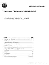
2. Mount the 1746-SIM on the input module. Align the Input Simulator release
screws with the mating connector on the module and press the Input
Simulator firmly onto the connector contacts. To avoid damage to the Input
Simulator connector/RTB, alternate between the two screws when
tightening.
3. Connect the 24V dc power supply to the terminals labeled A and B as stated
in the instructions on the Input Simulator. In most instances, the 24V dc user
power available in the SLC 500 power supply can be used. The Input
Simulator A/B terminal block is removable for convenience in making this
connection.
0
1
10
2
3
4
5
6
7
8
9
10
11
12
14
15
Secure the Input Simulator to the input module with the
captive screws. Alternate tighening to avoid damage.
11/64 inch dia.
through hole
24V dc
Input Power
Connector
USER POWER SUPPLY CONNECTION
128mA @ 24V dc max (All 16 inputs on)
Sourcing Input Module: A = DC COM B = +24V dc
Sinking Input Module: A = +24V dc B = DC COM
1746IN024AENP.fm Page 3 Tuesday, December 4, 2001 11:26 AM
Allen-Bradley Spares
Publication 1746-IN024A-EN-P - October 2001 PN 40071-142-01(1)
Copyright © 2001 Rockwell Automation. All rights reserved. Printed in the U.S.A.
For More Information
If you would like a manual, you can:
download a free electronic version from the internet:
www.theautomationbookstore.com
purchase a printed manual by:
contacting your local distributor or Rockwell Automation representative
visiting www.theautomationbookstore.com and placing your order
calling 1.800.963.9548 (USA/Canada)
or 001.330.725.1574 (Outside USA/Canada)
SLC 500 is a trademark of Rockwell Automation.
For Refer to this Document Pub. No.
A more detailed description on how to
install and use your modular SLC 500
system.
SLC 500 Modular Hardware
Style Installation and
Operation Manual
1747-UM011C-EN-P
Detailed information on installing and
wiring discrete I/O modules in an SLC
system.
Discrete I/O Modules
Installation Instructions
1746-IN005A-US-P
1746IN024AENP.fm Page 4 Tuesday, December 4, 2001 11:26 AM
  • Page 1 1
  • Page 2 2
  • Page 3 3
  • Page 4 4

Allen-Bradley SLC 500 Installation guide

Type
Installation guide

Allen-Bradley SLC 500 is a modular hardware system designed for industrial automation applications. It offers flexibility and expandability, allowing you to customize your system to meet specific requirements. With a wide range of I/O modules, communication options, and software tools, the SLC 500 can handle various tasks, including data acquisition, control, and monitoring. Its compact design and easy installation make it suitable for space-constrained environments.

Ask a question and I''ll find the answer in the document

Finding information in a document is now easier with AI