

Because of the variety of uses for the products described in this publication,
those responsible for the application and use of this control equipment must
satisfy themselves that all necessary steps have been taken to assure that each
application and use meets all performance and safety requirements, including
any applicable laws, regulations, codes, and standards.
The illustrations, charts, sample programs, and layout examples shown in
this guide are intended solely for purposes of example. Since there are
many variables and requirements associated with any particular installation,
Allen-Bradley does not assume responsibility or liability (to include
intellectual property liability) for actual use based upon the examples shown
in this publication.
Allen-Bradley publication SGI-1.1, Safety Guidelines For The Application,
Installation and Maintenance of Solid State Control (available at your local
Allen-Bradley office) describes some important differences between solid-
state equipment and electromechanical devices which should be taken into
consideration when applying products such as those described in this
publication.
Reproduction of the contents of this copyrighted publication, in whole or in
part, without written permission of Allen-Bradley Company, Inc. is prohibited.
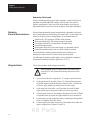
Throughout this manual we make notes to alert you to possible injury to people
or damage to equipment under specific circumstances.
ATTENTION: Identifies information about practices or
circumstances that can lead to personal injury or death, property
damage or economic loss.
Attention helps you:
- Identify a hazard
- Avoid the hazard
- Recognize the consequences
Important: Identifies information that is critical for successful application and
understanding of the product.
SLC, SLC 5/01, SLC 5/02, SLC 5/03, SLC 5/04, SLC 100, SLC 500, and DTAM are trademarks of Allen–Bradley Company, Inc.
Important User Information

Using This Manual
P-1
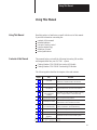
Using This Manual
Read this preface to familiarize yourself with the rest of this manual.
It provides information concerning the:
contents of this manual
intended audience
concept of analog control
common terminology
definition of terms
related publications
This manual helps you install the following fast analog I/O modules
and integrate them into your SLC 500 system.
Catalog Number 1746–FIO4I Fast Analog I/O Module
Catalog Number 1746–FIO4V Fast Analog I/O Module
The following table identifies the chapters, titles and contents.
Chapter Title Describes
1 Quick Start
Abbreviated procedures for the advanced
technician, or otherwise used as an overview
2 Installing Modules How to install and wire the module
3
Processor and Module
Considerations
Monitoring I/O data, addressing I/O image words,
signal resolution and conversion in I/O channels
4
Create or Open a File
and Configure the
Software
Procedures to create new files or return to existing
files to configure software or write ladder logic
5 Programming Examples How to program analog modules
6 Calibrating the Module
How to write ladder logic to maintain a calibrated
input reference and to calibrate the module
8
Maintenance, Safety,
and Troubleshooting
Preventive maintenance suggestions,
safety considerations, and troubleshooting
7 Testing Your Module How to test analog modules during initial installation
A Module Specifications Detailed technical specifications
B
2’s-complement Binary
Numbers
Explanation of how to use this number system
C Module I/O Circuits Internal wiring of the module’s I/O circuits
Using
This Manual
Contents of this Manual
AB Parts

Using
This Manual
P-2
We assume that you have a working knowledge of the SLC 500 family of
processors and related products. If you do not, obtain the proper training
from your local sales or distributor office.
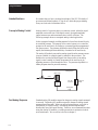
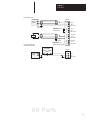
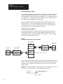
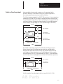
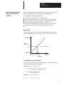
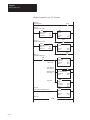
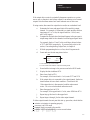
Analog control of a process refers to continuous control, where the signal
amplitude varies with time. With digital control, the signal amplitude
jumps between zero and a maximum value (on/off) with time. The
following example shows a conceptual analog control application.
In this conceptual example, molding material is forced into the mold cavity
at controlled pressure. The purpose of the control system is to control the
pressure in the mold cavity according to a pressure algorithm programmed
into the processor. The pressure algorithm controls filling the mold cavity
rapidly and attaining the desired density of material in the mold cavity.
The analog I/O module converts the analog signal from the pressure sensor
(process variable) to a digital signal for transfer to the processor. The
module also converts the digital signal from the processor to an analog
signal (control variable) to control the pressure in the mold cavity by
adjusting pressure or flow through the valve. The pressure algorithm is a
ladder program stored in processor memory.
Pressure
Sensor
SLC 500
Processor
Analog Input
Analog Output
Valve
Analog I/O
Module
inflow
Mold Cavity
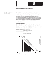
Standard analog I/O modules respond to changes in analog signals measured
in seconds. Fast analog I/O modules respond to changes in analog signals
measured in milliseconds. What you gain in faster response, you loose in
susceptibility to electrical noise. Fast analog modules respond faster
because they have little input filtering. Therefore, we recommend that when
using fast analog I/O modules, you take precautions to minimize electrical
noise interference. We cover how to do this in chapter 2.
Intended Audience
Concept of Analog Control
Fast Analog Response

Using
This Manual
P-3
For a complete glossary, refer to the Allen-Bradley Industrial Automation
Glossary, publication AG-7.1.
A/D Conversion
Generation of a digital value whose magnitude is proportional to the
instantaneous magnitude of an analog signal.
Common Mode Rejection
The ability of a differential analog input to cancel a common-mode signal,
expressed in dB.
Common Mode Voltage
A voltage that appears in common at both input terminals of a differential
analog input with respect to ground.
Common Mode Voltage Range
The largest voltage difference (positive or negative) allowed at either input
terminal of a differential analog input with respect to ground.
D/A Conversion
Generation of an analog signal whose instantaneous magnitude is
proportional to the magnitude of a digital value.
Differential Voltage, Maximum
The largest voltage difference allowed between the negative terminal and
positive terminal during normal differential operation.
Full Scale
The maximum voltage or current over which normal operation is measured.
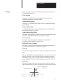
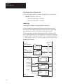
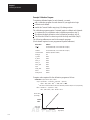
Gain
Ratio of output signal to input signal magnitudes. The “gain” of an analog
input or output is the scale factor which provides the nominal conversion
relationship. Typically, this is the slope of the line when analog voltage or
current is plotted versus the corresponding digital codes. (see Gain Error.)
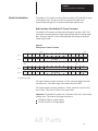
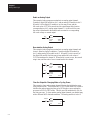
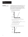
Gain Error
Gain error is the deviation of the scale factor or slope of the line from the
ideal or nominal value. Gain error is expressed in percent of input or output.
Gain Error = Change in slope
(exaggerated)
Actual Transfer Function
Nominal Transfer
Function
Glossary
AB Parts

Using
This Manual
P-4
Gain Error Drift
The effect of temperature on gain error is expressed by gain error drift.
As temperature varies from +25° C, the possible gain error increases.
The gain error drift is specified in percent of input or output value /° C.
I/O Rack
An assembly that typically holds the processor, power supply, and I/O
modules that plug into slots. In a modular system, it is a 4-, 7-, 10- or
13–slot I/O rack. In a fixed system, it is a 2–slot expansion I/O rack.
Least Significant Bit (LSB)
The digit (or bit) in a binary word that carries the smallest value or weight.
The right-most bit in a 16-bit 2’s-complement binary code. For the FIO4I
and FIO4V modules, the LSB is defined by I/O channel converters as:
for outputs, the 3rd rightmost bit, bit 02
for inputs, the right-most bit, bit 00
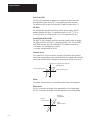
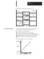
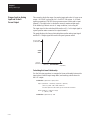
Linearity Error
For an ideal A/D or D/A conversion, a graph of the digital values plotted
against the corresponding analog values should form a straight line. Linearity
error is any deviation from a straight line expressed in percent of full scale.
Linearity Error = Variation from straight line
(exaggerated)
Actual Transfer Function
Linear Transfer Function
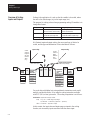
Offset
The steady-state deviation of a controlled variable from a fixed setpoint.
Offset Error
For A/D conversion, the digital value generated by a zero analog signal.
For D/A conversion, the digital value that generates a zero analog signal.
Offset Error
(exaggerated)
Nominal
Transfer Function
Actual
Transfer Function

Using
This Manual
P-5
Offset Error Drift
The change in offset error due to the change in temperature.
As temperature varies from +25° C, the possible offset error increases.
The offset error drift is specified in LSB /° C of full scale.
Overall Accuracy
For outputs, the worst case deviation of the output voltage or current from
the ideal over the full output range. For inputs, the worst case deviation of
the digital representation of the input signal from the ideal over the full
input range. It is expressed in percent of full scale.
Gain error, offset error, and linearity error all contribute to input and output
channel accuracy.
Resolution
The nominal voltage or current increment that equals the smallest change,
step or level, detected or represented by the analog channel. For A/D or
D/A conversion, may be expressed as the number of bits in the digital
value that corresponds to a full-scale analog value.
Safe State
The state to which analog outputs must be set when the processor is not in
RUN mode. The user must ensure that this is a safe state for the application.
Step Response Time
The time required for the digital representation of the analog input to reach
95% of the expected final value.
Update Time
For analog inputs, the time between updates to the memory of the analog
module of the digital value representing the analog input signal.
For analog outputs, the time from when the digital code is received at the
module to when the analog output signal corresponds to that digital value.
You may want to refer to these manuals while working with analog modules:
SLC 500 System Overview, Publication 1747-2.30
Getting Started Guide for APS, Publication 1747-6.3
Industrial Automation Wiring & Grounding Guidelines, Pub 1770-4.1
Advanced Programming Software User Manual, Publication 1747-6.4
Advanced Programming Software Reference, Publication 1747-6.11
Installation and Operation Manual for Fixed or Modular Hardware
Programmable Controllers, Publication 1747-6.2 or 1747-NI002
Safety Guidelines for the Application, Installation, and Maintenance
of Solid State Controls, Publication SGI–1.1
Related Publications
AB Parts

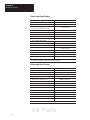
Table of Contents
i
Table of Contents
Chapter 1
Required Tools and Equipment 1–1. . . . . . . . . . . . . . . . . . . . . . . . . . . . . .
Procedures 1–2. . . . . . . . . . . . . . . . . . . . . . . . . . . . . . . . . . . . . . . . . . . . . .
Chapter 2
Determining the Module’s Power Requirements 2–1. . . . . . . . . . . . . . . .
Determining Compatibility with Other I/O Modules 2–2. . . . . . . . . . . . . .
Configuring Input Channels 2–3. . . . . . . . . . . . . . . . . . . . . . . . . . . . . . . . .
Selecting the I/O Rack Slot 2–3. . . . . . . . . . . . . . . . . . . . . . . . . . . . . . . . .
Installing the Module 2–3. . . . . . . . . . . . . . . . . . . . . . . . . . . . . . . . . . . . . .
Considerations When Wiring 2–5. . . . . . . . . . . . . . . . . . . . . . . . . . . . . . .
System Wiring Guidelines 2–5. . . . . . . . . . . . . . . . . . . . . . . . . . . . . . .
Grounding the Cable 2–5. . . . . . . . . . . . . . . . . . . . . . . . . . . . . . . . . . . .
Determining Cable Length 2–6. . . . . . . . . . . . . . . . . . . . . . . . . . . . . . .
Minimizing Electrical Noise Interference 2–6. . . . . . . . . . . . . . . . . . . . . .
Wiring the Module 2–6. . . . . . . . . . . . . . . . . . . . . . . . . . . . . . . . . . . . . . . .
Minimizing Ground Loops 2–8. . . . . . . . . . . . . . . . . . . . . . . . . . . . . . . . . .
Labeling the Terminal Block 2–8. . . . . . . . . . . . . . . . . . . . . . . . . . . . . . . .
Chapter 3
Create a New File 3–1. . . . . . . . . . . . . . . . . . . . . . . . . . . . . . . . . . . . . . . . .
Configure I/O 3–3. . . . . . . . . . . . . . . . . . . . . . . . . . . . . . . . . . . . . . . . . . .
Return to an Existing File 3–5. . . . . . . . . . . . . . . . . . . . . . . . . . . . . . . . . . .
Chapter 4
Processor Considerations 4–1. . . . . . . . . . . . . . . . . . . . . . . . . . . . . . . . . . .
Processor Update of Analog I/O Data 4–1. . . . . . . . . . . . . . . . . . . . . . .
Monitoring Analog I/O Data 4–2. . . . . . . . . . . . . . . . . . . . . . . . . . . . . .
Addressing I/O Image Words 4–2. . . . . . . . . . . . . . . . . . . . . . . . . . . . .
Module Considerations 4–3. . . . . . . . . . . . . . . . . . . . . . . . . . . . . . . . . . . . .
Data Resolution of the Module’s I/O Channel Converters 4–3. . . . . . .
Converting Analog Input Data 4–4. . . . . . . . . . . . . . . . . . . . . . . . . . . .
Compute the Analog Input Signal Level 4–4. . . . . . . . . . . . . . . . . . . . .
Converting Analog Output Data 4–4. . . . . . . . . . . . . . . . . . . . . . . . . . .
Compute the Analog Output 4–5. . . . . . . . . . . . . . . . . . . . . . . . . . . . . .
Input Channel Filtering 4–6. . . . . . . . . . . . . . . . . . . . . . . . . . . . . . . . . .
Time Delay for A/D Conversion 4-7. . . . . . . . . . . . . . . . . . . . . . . . . . .
Response to Slot Disable 4–7. . . . . . . . . . . . . . . . . . . . . . . . . . . . . . . . .
Safe State for Outputs 4–8. . . . . . . . . . . . . . . . . . . . . . . . . . . . . . . . . . .
Module I/D Code 4–7. . . . . . . . . . . . . . . . . . . . . . . . . . . . . . . . . . . . . . .
Quick Start
Installing and Wiring
Modules
Accessing Files
to Configure I/O
Processor and Module
Considerations

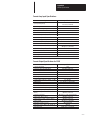
Table of Contents
ii
Chapter 5
Retentive and Non-retentive Programming 5–1. . . . . . . . . . . . . . . . . . . . .
Retain an Analog Output 5–2. . . . . . . . . . . . . . . . . . . . . . . . . . . . . . . .
Non-retentive Analog Output 5–2. . . . . . . . . . . . . . . . . . . . . . . . . . . . .
Clear the Output for Changing Mode or Cycling Power 5–2. . . . . . . .
Detect an Out-of-range Input 5–3. . . . . . . . . . . . . . . . . . . . . . . . . . . . . . . .
Overview of Scaling Inputs and Outputs 5–4. . . . . . . . . . . . . . . . . . . . . . .
Scale an Analog Input and Detect an Out-of-range Condition 5–5. . . . . .
Input Scaling 5–5. . . . . . . . . . . . . . . . . . . . . . . . . . . . . . . . . . . . . . . . .
Calculating the Linear Relationship 5–5. . . . . . . . . . . . . . . . . . . . . . . .
Calculating the Out-of-range Limits 5–6. . . . . . . . . . . . . . . . . . . . . . .
Ladder Logic 5–6. . . . . . . . . . . . . . . . . . . . . . . . . . . . . . . . . . . . . . . . .
Scale an Analog Output 5–7. . . . . . . . . . . . . . . . . . . . . . . . . . . . . . . . . . . .
Calculating the Linear Relationship 5–8. . . . . . . . . . . . . . . . . . . . . . . .
Ladder Logic 5–8. . . . . . . . . . . . . . . . . . . . . . . . . . . . . . . . . . . . . . . . .
Scale Offsets When > 32,768 or < –32,768 5–10. . . . . . . . . . . . . . . . . . . . .
Ladder Logic 5–11. . . . . . . . . . . . . . . . . . . . . . . . . . . . . . . . . . . . . . . . .
Range-check an Analog Input and Scale It For an Output 5-12. . . . . . . . . .
Calculating the Linear Relationship 5–12. . . . . . . . . . . . . . . . . . . . . . . .
Ladder Logic 5–13. . . . . . . . . . . . . . . . . . . . . . . . . . . . . . . . . . . . . . . . .
PID Control with Analog I/O Scaling 5-16. . . . . . . . . . . . . . . . . . . . . . . . .
Ladder Logic 5–17. . . . . . . . . . . . . . . . . . . . . . . . . . . . . . . . . . . . . . . . .
Chapter 6
Calibration Tradeoffs 6–1. . . . . . . . . . . . . . . . . . . . . . . . . . . . . . . . . . . . . .
Calibrating an Analog Input Channel 6–1. . . . . . . . . . . . . . . . . . . . . . . . . .
Example Calibration Program 6–2. . . . . . . . . . . . . . . . . . . . . . . . . . . .
Calibration Procedure 6–5. . . . . . . . . . . . . . . . . . . . . . . . . . . . . . . . . . .
Chapter 7
Testing the SLC 500 System 7–1. . . . . . . . . . . . . . . . . . . . . . . . . . . . . . . .
Testing the Module 7–1. . . . . . . . . . . . . . . . . . . . . . . . . . . . . . . . . . . . . . . .
1. Inspect Module Switches and Wiring 7–1. . . . . . . . . . . . . . . . . . . .
2. Disconnect Analog Process Control Devices 7–2. . . . . . . . . . . . . . .
3. Power Up the I/O Rack 7–2. . . . . . . . . . . . . . . . . . . . . . . . . . . . . . .
4. Test Analog Inputs 7–3. . . . . . . . . . . . . . . . . . . . . . . . . . . . . . . . . . .
5. Test Analog Outputs 7–4. . . . . . . . . . . . . . . . . . . . . . . . . . . . . . . . . .
Chapter 8
Preventive Maintenance 8–1. . . . . . . . . . . . . . . . . . . . . . . . . . . . . . . . . . . .
Safety Considerations When Troubleshooting 8–1. . . . . . . . . . . . . . . . . . .
Writing Ladder Logic
Calibrating the Module
Testing Module Operation
Maintenance and Safety
AB Parts

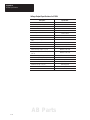
Table of Contents
iii
Appendix A
General Description A–1. . . . . . . . . . . . . . . . . . . . . . . . . . . . . . . . . . . . . . .
Specifications A–1. . . . . . . . . . . . . . . . . . . . . . . . . . . . . . . . . . . . . . . . . . . .
General Specifications A–1. . . . . . . . . . . . . . . . . . . . . . . . . . . . . . . . . .
General Input Specifications A–2. . . . . . . . . . . . . . . . . . . . . . . . . . . . . .
Voltage input Specifications A–2. . . . . . . . . . . . . . . . . . . . . . . . . . . . . .
Current-loop Input Specifications A–3. . . . . . . . . . . . . . . . . . . . . . . . . .
Current Output Specifications for FIO4I A–3. . . . . . . . . . . . . . . . . . . .
Voltage Output Specifications for FIO4V A–4. . . . . . . . . . . . . . . . . . . .
Appendix B
Using 2’s-complement Binary Numbers B–1. . . . . . . . . . . . . . . . . . . . . . .
Positive Decimal Values B–1. . . . . . . . . . . . . . . . . . . . . . . . . . . . . . . . .
Negative Decimal Values B–2. . . . . . . . . . . . . . . . . . . . . . . . . . . . . . . .
Appendix C
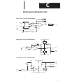
Input and Output Circuits C–1. . . . . . . . . . . . . . . . . . . . . . . . . . . . . . . . . . .
Index I–1. . . . . . . . . . . . . . . . . . . . . . . . . . . . . . . . . . . . . . . . . . . . . . . . . .
2.1 Installing the Module 2–4. . . . . . . . . . . . . . . . . . . . . . . . . . . . . . . . . .
2.2 Typical Signal Cable 2–5. . . . . . . . . . . . . . . . . . . . . . . . . . . . . . . . . . .
2.3 Cable Preparation 2–7. . . . . . . . . . . . . . . . . . . . . . . . . . . . . . . . . . . . .
2.4 Wiring Diagram for Module, Sensor, and Load 2–7. . . . . . . . . . . . . .
2.5 Wiring Schematic for Single-ended Current-loop Analog Inputs 2–8.
2.6 Terminal Block 2–8. . . . . . . . . . . . . . . . . . . . . . . . . . . . . . . . . . . . . . .
4.1 Processor I/O Image Words Used by the Module 4–2. . . . . . . . . . . . .
4.2 Bit Usage of the Module’s I/O Channel Converters 4–3. . . . . . . . . . .
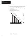
4.3 Percent of Signal Passed 4–6. . . . . . . . . . . . . . . . . . . . . . . . . . . . . . . .
4.4 Input Channel Frequency Response 4–6. . . . . . . . . . . . . . . . . . . . . . .
4.5 Response Time of A/D Converter 4–7. . . . . . . . . . . . . . . . . . . . . . . . .
C.1 Module Input and Output Circuits C–1. . . . . . . . . . . . . . . . . . . . . . . .
Module Specifications
2’s-complement
Binary Numbers
Module Input and Output
Circuits
Index
List of Figures

1
Chapter
1–1
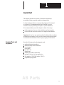
Quick Start
This chapter presents an overview of installation and start-up
procedures to help you get the module working quickly.
It refers to full procedures in corresponding chapters of this manual
or in other SLC documentation that may be helpful if you are
unfamiliar with programming techniques or system installation.
We recommend that you use this chapter in either of two ways:
for the experienced user as a fast installation and start-up guide
for the first-time user as an overview for using the entire manual
Important: If you have any questions about the abbreviated procedures
presented in this chapter, always read the referenced chapters and other
recommended documentation before trying to apply the information.
Have the following tools and equipment ready:
medium flat-head screwdriver
medium Phillips–head screwdriver
wire strippers
utility knife
hot-air blower
shrink wrap
Belden 8761 cable or equivalent
analog I/O devices for your application
I/O modules (1746-FIO4I and/or -FIO4V)
programming equipment
Required Tools and
Equipment
AB Parts

Chapter 1
Quick Start
1–2
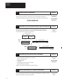
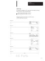
1. Plan
the inclusion of analog I/O modules in your SLC system.
Reference
If a new system, specify the type of processor, number of I/O racks, I/O modules, and power supply.
If adding to an existing system:
• assign modules to slot locations in the I/O rack
• verify that the power supply for the I/O rack can handle the increased load
Worksheet
at end of chapter
SLC 500 Overview
pub 1747-2.30
2. Configure
module input channels for current or voltage operation.
Reference
Locate the 2-switch assembly on the module’s circuit board, and set each channel as follows:
(The example shows channel 1 set for current and channel 2 set for voltage operation.)
Chapter 2
Installing the
Module
1
2
N
O
Switch 1 = Channel 0
Switch 2 = Channel 1
Current (ON)
Voltage (OFF)
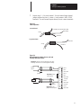
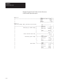
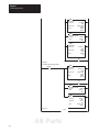
3.
Connect I/O devices with cables.
Reference
Important:
• Connect only one end of the cable shield to earth ground.
• Channels are not isolated from each other. All analog commons are connected together internally.
• The module does not provide loop power for analog inputs.
• Use a power supply that matches the transmitter (sensor) specifications.
Chapter 2
Installing the
Module
Procedures

Chapter 1
Quick Start
1–3
0
1
2
9
10
11
IN 0 +
IN 0 –
ANL COM
IN 1 +
IN 1 –
ANL COM
not used
OUT 0
ANL COM
not used
OUT 1
ANL COM
3
4
5
6
7
8
Important: Do not
jumper unused outputs
Important:
Jumper
unused inputs
Load
earth
ground
earth
ground
For Single-ended Input
with 3-Wire Transmitter
Transmitter
Supply Signal
GND
IN +
IN –
ANL COM
Module
+
Power
Supply
–
Module
+Analog
Sensor
–
3
4
5
For Differential Inputs
AB Parts

Chapter 1
Quick Start
1–4
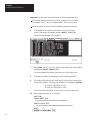
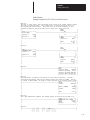
4. Configure
system I/O and module ID.
Reference
With APS, software configure the processor, I/O racks, slots, and I/O modules.
When assigning an I/O module to a slot location, select the module from the displayed list.
If not listed, select Other at the bottom of the list and enter the module’s ID code at the prompt.
ID code for 1746-FIO4I is 3224
ID code for 1746-FIO4V is 3218
Chapter 3
Accessing Files to
Configure I/O
APS User Manual
pub. 1747-6.4
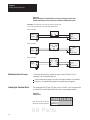
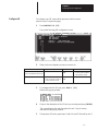
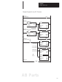
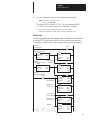
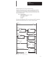
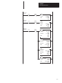
5. Understand A/D & D/A converter resolution on input and output words.
Reference
The module’s I/O channel converters limit bit usage to less than a full 16-bit word.
The input channel converter resolution is 12 bits, where the highest four bits are always zero.
The output channel converter resolution is 14 bits, where the lowest two bits are never used.
The lowest two bits have no effect on the output value.
Chapter 4
Processor and
Module
Considerations
Channel 1 Input W
ord
Output Image
SLC 500 Processor
Data Files
Bit
15
Bit 0
Input Image
0
0
0
0
Channel 0 Input Word
(2 words)
(V
ariable Input Data)
Address
I:1.0
I:1.1
msb lsb
(2 words)
Bit 1
1
Bit 15
Bit 0
(V
ariable Output Data)
Address
O:1.0
O:1.1
msb lsb
Bit 2
Channel 1 Output W
ord
Channel 0 Output Word
xx
x = not used
6. Write
ladder logic to process the module’
s analog data.
Reference
We provide several programming examples that include:
• clear the output when changing mode or cycling power
• detect an out-of-range input
• scale analog outputs
• scale offsets
• scale and range-check analog inputs and outputs
• PID control with analog I/O scaling
Study these examples to understand how to program the module.
Chapter 5
Writing Ladder
Logic
APS User Manual
pub. 1747-6.4
7. (Optional) W
rite ladder logic to maintain calibrated inputs.
Reference
We
show you how to write ladder logic that provides a calibrated input reference during runtime, and lets
you periodically calibrate module inputs. We suggest that you modify the logic examples to suit your
application and add them to your application program.
Chapter 6
Calibrating the
Module

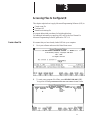
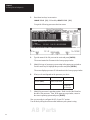
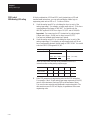
01 02 03 04 05 06 07 08 09 10 11 12 13
Inputs
Digit Anlog
Outputs
Digit Anlog
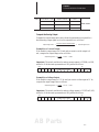
4-slot > 7-slot > 10-slot > 13-slot >2-slot >
Slt Module I@5v I@24v
Rack 1
01
02
03
04
05
06
07
08
09
10
11
12
13
Total
PS Spec
Slt Module I@5v I@24v
Rack 2
Total
PS Spec
Slt Module I@5v I@24v
Rack 3
Total
PS Spec
Power Supply I@5v I@24v
1746-P1
1746-P2
1746-P3
1746-P4
2.0A 0.46A
Processor I@5v I@24v
SLC 5/01 0.35 0.105
0.35 0.105
0.50 0.175
SLC 5/02
SLC 5/03
SLC 5/04 0.65 0.200
5.0A 0.96A
3.6A 0.87A
00 Proc < < < <
< < < < 10.0A 2.8A
Chapter 1
Quick Start
1–5
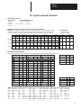
SLC System Configuration Worksheet
1. Identify the SLC processor
.
Processor Type SLC 5/03 Operating System
SLC 5/01 _______ (from processor label)
SLC 5/02 _______
SLC 5/03 _______ >>>> OS300 ____ or OS301 ___
SLC 5/04 _______
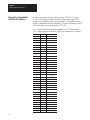
2. Identify I/O rack types and assign I/O modules to slot locations (30 slots max).
Important: FIO4I and FIO4V modules are sensitive to radiated electrical noise and temperature variations. 3. Tally I/O points.
Select I/O slots farthest from ac modules, high-voltage dc modules, power supplies, and other heat sources.
Enter totals of digital
If using an enclosure, locate these modules in the coolest area of the enclosure, usually near the bottom. and analog I/O points.
Rack 1
___-Slot
Rack 2
___-Slot
Rack 3
___-Slot
4. Identify power supply requirements.
Enter module power requirements by slot location. Total module power must be less than that of the power supply.
Module I@5v I@24v Module I@5v I@24v Module I@5v I@24v Module I@5v I@24v Module I@5v I@24v Module I@5v I@24v
FIO4I 0.055 0.150 IG16 0.140 – ITB16 0.085 – NO4V 0.055 0.145 OG16 0.180 – BASIC 0.150 0.040
FIO4V 0.055 0.120 IM4 0.035 – ITV16 0.085 – NT4 0.060 0.020 OV8 0.135 – BASICn 0.150 0.125
IA4 0.035 – IM8 0.050 – IV8 0.050 – OA8 0.185 – OV16 0.270 – DCM 0.360 –
IA8 0.050 – IM16 0.085 – IV16 0.085 – OA16 0.370 – OV32 0.452 – HS 0.300 –
IA16 0.085 – IN16 0.085 – IV32 0.106 – OB8 0.135 – OW4 0.045 0.045 KE 0.150 0.040
IB8 0.050 – IO4 0.030 0.025 NIO4I 0.055 0.145 OB16 0.280 – OW8 0.085 0.090 KEn 0.150 0.145
IB16 0.085 – IO8 0.060 0.045 NIO4V 0.055 0.115 OB32 0.452 – OW16 0.170 0.180
IB32 0.106 – IO12 0.090 0.070 NO4I 0.055 0.195 OBP16 0.250 – OX8 0.085 0.090 NI4 0.025 0.085
AB Parts

2
Chapter
2–1
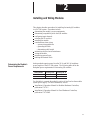
Installing and Wiring Modules
This chapter describes procedures for installing fast analog I/O modules
in a SLC 500 system. Procedures include:
determining the module’s power requirements
determining compatibility with other I/O modules
configuring input channels
selecting the I/O rack slot
installing the module
considerations when wiring
– system wiring guidelines
– grounding the cable
– determining cable length
minimizing electrical noise interference
wiring the module
minimizing ground loops
labeling the terminal block
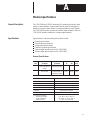
Analog modules require power from the 5V dc and 24V dc backplane
power supplies of the SLC 500 system. The following table shows the
backplane power requirements for fast analog I/O modules.
Catalog Number Current @ 5V dc Current @ 24V dc
1746–FIO4I 55 mA 150 mA
1746–FIO4V 55mA 120mA
Use this table to compute the module’s portion of total load on the modular
system power supply. For more information, refer to:
Installation & Operation Manual for Modular Hardware Controllers,
publication 1747-6.2
Installation & Operation Manual for Fixed Hardware Controllers,
publication 1747-NI001
Determining the Module’s
Power Requirements

Chapter 2
Installing and Wiring Modules
2–2
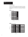
If using the expansion rack of a fixed controller (1747-L20, -L30, and
-L40), use the following chart to determine whether other types of I/O
modules are compatible with fast analog modules. Compatibility is solely
based on current drawn from the backplane. For more information, refer to
SLC 500 System Overview, publication 1747-2.30.
The
• symbol indicates an allowable combination of 1746 I/O modules.
The
o symbol indicates an auxiliary 24Vdc power supply may be needed.
FIO4I FIO4V Module
FIO4I
FIO4V
• •
IA4,
IA8, IA16
• •
IB8, IB16
• •
IB32
• •
IG16
• •
IM4, IM8, IM16
• •
IN16
• •
IO4
•
IO8
IO12
• •
ITB16, ITV16
• •
IV8, IV16, IV32
NIO4I, NIO4V
o o
NO4I, NO4V
NI4
• •
NR4
• •
NT4
• •
OA8
OA16
• •
OB8
OB16, OB32
•
OBP16
• •
OG16
• •
OV8
•
OV16
OV32
•
OW4
OW8, OW16
OX8
•
BASIC
BASn
DCM
HS
•
KE
KEn
Determining Compatibility
with Other I/O Modules
AB Parts

Chapter 2
Installing and Wiring Modules
2–3
Your fast analog I/O modules have a 2-switch assembly to configure the
input channels for either current or voltage operation. The switches are
located on the module’s circuit board. Switch orientation is shown on the
nameplate of the module as follows:
ON – Configures channel for current input
Off – Configures channel for voltage input
Switches labeled 1 and 2 control the input mode of channels 0 and 1
respectively, as follows:
12
N
O
Switch 1 = Channel 0
Switch 2 = Channel 1
Current (ON)
Voltage (OFF)
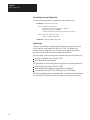
Two factors determine where you should locate the module in the I/O rack:
ambient temperature and electrical noise. Consider the following conditions
when selecting an I/O rack slot for the module. Position the module:
in a slot away from ac or high voltage dc modules
away from the rack power supply if installed in a modular system
in the I/O rack lowest in the enclosure for a cooler ambient
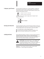
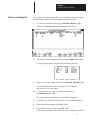
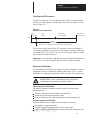
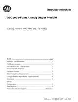
When installing the module in an I/O rack, you do not need to remove the
terminal block from the module. However, if the terminal block is
removed, use the write–on label located on the side of the terminal block to
identify the module location and type. To remove the terminal block,
grasp it on the top and bottom and pull outward and down.
ATTENTION: Never install, remove, or wire modules with
power applied to the I/O rack. Rid yourself of electrostatic
charge before handling the module. Electrostatic discharge can
degrade module performance or destroy analog circuitry.
Important – Do not tamper with the the module’s factory-sealed
potentiometer. It does not require any adjustments.
Configuring Input Channels
Selecting the I/O Rack Slot
Installing the Module

Chapter 2
Installing and Wiring Modules
2–4
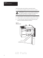
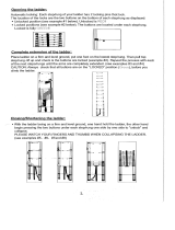
Follow this procedure when installing or removing the module.
1. Verify that input configuration switches 1 and 2 are set correctly.
ATTENTION: Take care to avoid connecting a voltage source
to a channel configured for current input. This could result in
improper module operation or damage to the module.
2. Align the module’s circuit board with the rack’s card guide (Figure 2.1).
3. Slide the module in until top and bottom retaining clips are secured.
4. To remove the module, depress the retaining clips at the top and
bottom of the module and slide the module out.
Figure 2.1
Installing the Module
Self–locking
tabs secure
the module in the I/O rack.
Card guide
AB Parts

Chapter 2
Installing and Wiring Modules
2–5
This section provides guidelines on wiring the system, grounding the
cables, determining cable length.
ATTENTION: Before wiring the module, disconnect
SLC system power, I/O rack power, and module power.
System Wiring Guidelines
Use the following guidelines in planning the system wiring to the module:
analog common terminals (ANL COM) are electrically interconnected
inside the module, but not internally connected to earth.
voltages on IN+ and IN– terminals must be within 0 to 20 volts
with respect to ANL COM to ensure proper input channel operation.
This is true for current and voltage input channel operation
.
voltage outputs (OUT 0 and OUT 1) of the FIO4V are referenced to
ANL COM. Load resistance (R1) for a voltage output channel must
be equal to or greater than 1K ohms.
current output channels (OUT 0 and OUT 1) of the FIO4I source current
that returns to ANL COM. Load resistance (R1) for a current output
channel must be within 0 to 500 ohms.
input connections for single–ended or differential input are the same.
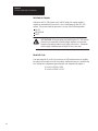
Grounding the Cable
Signal cable such as Belden cable #8761 (or equivalent) has two signal
wires (black and clear), one drain wire and a foil shield (Figure 2.2).
The drain wire and foil shield must be grounded at only one end of the
cable, not at both ends.
Figure 2.2
Typical Signal Cable
Foil Shield
Black Wire
Drain Wire
C
lear W
i
re
Insulation
Shrink Wrap
Important: Ground the cable shield at one end having a good earth-
ground connection, such as at an I/O chassis mounting bolt or nearest
ground bus in the I/O enclosure. Make this connection as short as possible.
Do not ground the cable at the module’s terminal block.
Considerations When Wiring
Page is loading ...
Page is loading ...
Page is loading ...
Page is loading ...
Page is loading ...
Page is loading ...
Page is loading ...
Page is loading ...
Page is loading ...
Page is loading ...
Page is loading ...
Page is loading ...
Page is loading ...
Page is loading ...
Page is loading ...
Page is loading ...
Page is loading ...
Page is loading ...
Page is loading ...
Page is loading ...
Page is loading ...
Page is loading ...
Page is loading ...
Page is loading ...
Page is loading ...
Page is loading ...
Page is loading ...
Page is loading ...
Page is loading ...
Page is loading ...
Page is loading ...
Page is loading ...
Page is loading ...
Page is loading ...
Page is loading ...
Page is loading ...
Page is loading ...
Page is loading ...
Page is loading ...
Page is loading ...
Page is loading ...
Page is loading ...
Page is loading ...
Page is loading ...
Page is loading ...
Page is loading ...
Page is loading ...
Page is loading ...
Page is loading ...
Page is loading ...
Page is loading ...
Page is loading ...
Page is loading ...
Page is loading ...
Page is loading ...
Page is loading ...
Page is loading ...
-
 1
1
-
 2
2
-
 3
3
-
 4
4
-
 5
5
-
 6
6
-
 7
7
-
 8
8
-
 9
9
-
 10
10
-
 11
11
-
 12
12
-
 13
13
-
 14
14
-
 15
15
-
 16
16
-
 17
17
-
 18
18
-
 19
19
-
 20
20
-
 21
21
-
 22
22
-
 23
23
-
 24
24
-
 25
25
-
 26
26
-
 27
27
-
 28
28
-
 29
29
-
 30
30
-
 31
31
-
 32
32
-
 33
33
-
 34
34
-
 35
35
-
 36
36
-
 37
37
-
 38
38
-
 39
39
-
 40
40
-
 41
41
-
 42
42
-
 43
43
-
 44
44
-
 45
45
-
 46
46
-
 47
47
-
 48
48
-
 49
49
-
 50
50
-
 51
51
-
 52
52
-
 53
53
-
 54
54
-
 55
55
-
 56
56
-
 57
57
-
 58
58
-
 59
59
-
 60
60
-
 61
61
-
 62
62
-
 63
63
-
 64
64
-
 65
65
-
 66
66
-
 67
67
-
 68
68
-
 69
69
-
 70
70
-
 71
71
-
 72
72
-
 73
73
-
 74
74
-
 75
75
-
 76
76
-
 77
77


Allen-Bradley SLC 500 1746–FIO4I User manual
- Type
- User manual
- This manual is also suitable for
Ask a question and I''ll find the answer in the document
Finding information in a document is now easier with AI
Related papers
-
Allen-Bradley SLC 500 1747-L552 Operating instructions
-
Allen-Bradley SLC 500 User manual
-
-
-
-
-
-
-
-
Other documents
-
 OxGord LDAL-TS02-12 User manual
-
 Rockwell Automation CDN366 Specification
-
 Helm HM1525 User manual
-
 The Helman Group HM1525 User manual
-
 Rockwell Automation 1746-NO8V Installation Instructions Manual
-
 Rockwell Automation Allen-Bradley SLC 500 User manual
-
Spectrum Controls 1746sc-CTR4 Owner's manual
-
Scosche SLC4 User manual
-
Rockwell Automation 1746-P2 Installation Instructions Manual
-
 Rockwell Automation Allen-Bradley B Series Installation Instructions Manual


