Installing And Wiring Your Module 2-3
Publication 1746-6.22
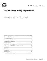
Fixed I/O Chassis - I/O Module Compatibility
The following chart depicts the range of current combinations
supported by the fixed I/O expansion chassis. To use it, find the
backplane current draw and operating voltage for both modules being
used in the chassis. These specifications are found in the table
alongside the chart.
Next, plot each of the currents on the chart below. If the point of
intersection falls within the operating region, the combination is
valid. If not, the combination cannot be used in a 2-slot, fixed I/O
chassis.
Module Current Draw - Power Supply Loading
I/O Module 5V 24V I/O Module 5V 24V
BAS .150 .040 KE .150 .040
BASn .150 .125 KEn .150 .125
DCM .360 .000 NI4 .025 .085
FIO4I .055 .150 NI8 .200 .100
FIO4V .055 .120 NIO4I .055 .145
HS .300 .000 NIO4V .055 .115
HSTP1 .200 .000 NO4I .055 .195
IA4 .035 .000 NO4V .055 .145
IA8 .050 .000 NR4 .050 .050
IA16 .085 .000 NT4 .060 .040
IB8 .050 .000 OA16 .370 .000
IB16 .085 .000 OA8 .185 .000
IB32 .106 .000 OAP12 .370 .000
IC16 .085 .000 OB8 .135 .000
IG16 .140 .000 OB16 .280 .000
IH16 .085 .000 OB16E .135 .000
IM4 .035 .000 OB32 .452 .000
IM8 .050 .000 OBP8 .135 .000
IM16 .085 .000 OBP16 .250 .000
IN16 .085 .000 OG16 .180 .000
IO4 .030 .025 OV8 .135 .000
IO8 .060 .045 OV16 .270 .000
IO12 .090 .070 OV32 .452 .000
ITB16 .085 .000 OVP16 .250 .000
ITV16 .085 .000 OW16 .170 .180
IV8 .050 .000 OW4 .045 .045
IV16 .085 .000 OW8 .085 .090
IV32 .106 .000 OX8 .085 .090
Example: Plot IN16 and NIO4V
IN16 = 0.085 at 5V dc and 0A at 24V dc
NIO4V = 0.055A at 5V dc and 0.115A at 24V dc
1. Add current draws of both modules at 5V dc to get 0.14
(140mA)
2. Plot this point on the chart above (140mA at 5V dc).
3. Add current draws of both modules at 24V dc to get
0.115A (115mA)
4. Plot current draw at 24V dc (115mA at 24V dc)
5. Note the point of intersection on the chart above
(marked x). This combination falls within the valid
operating region for the fixed I/O chassis.
Important: The1746-NO4I and 1746-NO4V analog output
modules may require an external power supply.
at 5V dc
x
Valid Operating
Region