Page is loading ...

0171--976 1
Mounting Instruction
A newsletter from YORK Refrigeration, Technology & Products
Christian X’s Vej 201, P O Box 1810, DK-8270 Højbjerg, Denmark
Phone +45 87 36 70 00, Fax +45 87 36 77 05
29 May 2001
Subject: Mounting of New Type of Capacity Rod on
SAB 81 Screw Compressors
As described in Technical Information 2001/03, a new capacity measuring system for SAB 81
screw compressors was introduced in May/June 2001.
The electronic control systems used so far can still be used for the new system, but the capacity
rod (capacity transmitter) on the compressor must be replaced. The capacity rod can be re-
placed by following a straightforward mounting procedure, which is described in this Mounting
Instruction. This instruction also describes how the capacity measuring system is adjusted to
the new sensor.
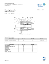
A kit is used for mounting the new capacity rod. This kit consists of the parts mentioned below
(see fig. 1).
Fig. 1
45
42 167
280
233
282
44a
43
203
141
280a
281
283

0171--976
2
Quantity Pos. no. Part no.
Complete Kit 3084-637
Capacity rod with threaded
bushing pos. 280a 1 280 1553-273
Retainer for regulating piston 1 42 3013-365
Stop screws M6X6 2 44a 1413-229
Bushing for capacity transmitter 1 281 3043-251
Dowty ring 1 167 1331-433
Aluminium pipe 1 282 1116-029
Hexagon socket screw M6X35 2 283 1413-344
O-ring ID 104.5x3 1 203 1331-374
Cover 1 45 3013-305
Dismounting
When the pressure in the compressor has been reduced to atmospheric pressure and the com-
pressor has been secured against unintentional start-up as described in the Instruction
Manual, proceed as follows (see sectional views in the instruction manual):
SDismount the electric plug on the existing capacity rod.
SDismount the existing capacity rod pos. 280 by means of an open-end spanner JW 24
and pull it out of the compressor carefully. Both the capacity rod and the gasket pos. 141
arenotgoingtobereused.
SDismount the hexagon socket screws pos. 233 (Allen key JW 8) and push out the cover
pos. 45 by mounting the screws pos. 233 in the two threaded holes in the flange.
The cover and the O-ring pos. 203 are not going to be reused.
SDismount the Seeger ring pos. 141 by means of a pair of seeger ring pliers and remove
manually the two magnets pos. 44.

0171--976 3
Mounting
When the parts to be mounted have been cleaned and suitably oiled, proceed as follows:
SPlace the retainer for the regulating piston pos. 42 on the aluminium pipe pos. 282 with
adistanceof10mmfromtheendasillustratedinfig.2.Tightenthetwostopscrews
(Allen key JW 2.5).
Fig. 2 10
250
282 42
44a
SPlace the arrangement in the retainer pos. 43 as shown in fig. 1 and lock it with the
Seeger ring pos. 141.
SWhen the new O-ring pos. 203 has been mounted on the new cover pos. 45, the cover
is mounted on the compressor as shown in fig. 1.
STighten the screws pos. 233.
SMount the Dowty ring pos. 167 and tighten the threaded bushing pos. 280a.
SBy pressing the bushing pos. 281 against the cover pos. 45 (remember to turn the
bushing as illustrated in the drawing), place the capacity rod pos. 280 in its position
and tighten the screws pos. 283.

0171--976
4
The same electric plug can be used for the new capacity rod as for the previous rod. It is how-
ever recommended to check that the wiring connections comply with fig. 3.
1 = OUT 4--20mA
2 = SUPPLY +24V DC
3 = COMMON --
=GND
Fig. 3
Adjusting capacity measuring system
As shown in fig. 4 the capacity transmitter is equipped with a single calibration button sur-
rounded by a green and red LED.
Fig. 4
During normal operation, the red LED is flashing at a rather slow rate. The green LED is con-
stantly on when the transmitter is in its 100% position, and it flashes quickly when it is in the
0% position.

0171--976 5
The calibration is done as follows:
Note! Make sure that the Unisab II is not in alarm.
1. Apply supply voltage minimum 5 minutes before calibration.
2. Press the calibration button for 5 seconds to get the transmitter in calibration
mode. The red LED changes from normal flash to OFF.
3. Decrease the capacity to its minimum, and then press the calibration button
once. The red LED turns immedially ON. After 10 seconds the red LED turns
OFF again, indicating that it is ready for 100% calibration.
4. Increase the capacity to its maximum, and then push the calibration button
twice. The red LED starts flashing quickly. After 10 seconds the red LED
changes to normal flash rate, indicating thatthe calibration has been completed.
5. The calibration will be remembered, even if a power failure occurs.
To return to “Factory Set Point”, press the CAL. Switch for 20 seconds.
Indication of this is shown by a short flash of the green and red led (one after the other).
The 4--20 mA signal from the transmitter is permanently available, however, during calibration
the signal is based on the default calibration values, so it will not show 0% at minimum capacity
nor 100% at maximum capacity! Note that it is possible to reset to the default calibration by
pressing the button pressed for 20 seconds, however, it is the transmitter manufacturer’s de-
fault values, which might differ very much from the proper values for the actual compressor.
The reset is indicated by the red and the green LED flashing briefly in turn a couple of times.

0171--976
6

0171--976 7

0171--976
8
YORK REFRIGERATION
Chr. X’s Vej 201 ·P. O . B o x 181 0 ·DK-8270 Højbjerg ·Denmark
Phone+4587367000 ·Fax +45 87 36 77 05
/