Page is loading ...

user'sguide
your Gateway 850
SCSI storage enclosure
Installing
Configuring


i
Contents
1 About the Gateway 850 SCSI Storage Enclosure . . . . . . . . . . . . . . . . 1
Welcome . . . . . . . . . . . . . . . . . . . . . . . . . . . . . . . . . . . . . . . . . . . . . . . . . . . . . . . . . . 2
Features . . . . . . . . . . . . . . . . . . . . . . . . . . . . . . . . . . . . . . . . . . . . . . . . . . . . . . . . . . . 3
Front . . . . . . . . . . . . . . . . . . . . . . . . . . . . . . . . . . . . . . . . . . . . . . . . . . . . . . . . . . . . . 4
Back . . . . . . . . . . . . . . . . . . . . . . . . . . . . . . . . . . . . . . . . . . . . . . . . . . . . . . . . . . . . . . 4
Components . . . . . . . . . . . . . . . . . . . . . . . . . . . . . . . . . . . . . . . . . . . . . . . . . . . . . . . 5
Front bezel . . . . . . . . . . . . . . . . . . . . . . . . . . . . . . . . . . . . . . . . . . . . . . . . . . . . . 5
Converting to a dual-backplane device . . . . . . . . . . . . . . . . . . . . . . . . . . . . . . . 6
AC power . . . . . . . . . . . . . . . . . . . . . . . . . . . . . . . . . . . . . . . . . . . . . . . . . . . . . . 7
Cooling fan module . . . . . . . . . . . . . . . . . . . . . . . . . . . . . . . . . . . . . . . . . . . . . . . 8
SAF-TE Disk I/O card . . . . . . . . . . . . . . . . . . . . . . . . . . . . . . . . . . . . . . . . . . . . . 9
RS-232 ports . . . . . . . . . . . . . . . . . . . . . . . . . . . . . . . . . . . . . . . . . . . . . . . . . . . 10
Control and monitoring . . . . . . . . . . . . . . . . . . . . . . . . . . . . . . . . . . . . . . . . . . . . . . 11
Status indicator LEDs . . . . . . . . . . . . . . . . . . . . . . . . . . . . . . . . . . . . . . . . . . . . 11
Drive LEDs . . . . . . . . . . . . . . . . . . . . . . . . . . . . . . . . . . . . . . . . . . . . . . . . . . . . 12
Audible alarm . . . . . . . . . . . . . . . . . . . . . . . . . . . . . . . . . . . . . . . . . . . . . . . . . . 12
2 Setup and Installation. . . . . . . . . . . . . . . . . . . . . . . . . . . . . . . . . . . . . . . . . . . 13
Overview . . . . . . . . . . . . . . . . . . . . . . . . . . . . . . . . . . . . . . . . . . . . . . . . . . . . . . . . . 13
Enclosure detailed installation . . . . . . . . . . . . . . . . . . . . . . . . . . . . . . . . . . . . . . . . . 15
Installing the storage enclosure in a rack cabinet . . . . . . . . . . . . . . . . . . . . . . 15
Enclosure configuration . . . . . . . . . . . . . . . . . . . . . . . . . . . . . . . . . . . . . . . . . . . . . . 21
Host cabling . . . . . . . . . . . . . . . . . . . . . . . . . . . . . . . . . . . . . . . . . . . . . . . . . . . . . . . 28
Turning on the enclosure . . . . . . . . . . . . . . . . . . . . . . . . . . . . . . . . . . . . . . . . . . . . 29
Turning off the enclosure . . . . . . . . . . . . . . . . . . . . . . . . . . . . . . . . . . . . . . . . . . . . 29
3 Monitoring Systems. . . . . . . . . . . . . . . . . . . . . . . . . . . . . . . . . . . . . . . . . . . . . 31
Enclosure component monitoring . . . . . . . . . . . . . . . . . . . . . . . . . . . . . . . . . . . . . . 32
Status indicator LEDs . . . . . . . . . . . . . . . . . . . . . . . . . . . . . . . . . . . . . . . . . . . . 32
Drive LEDs . . . . . . . . . . . . . . . . . . . . . . . . . . . . . . . . . . . . . . . . . . . . . . . . . . . . 33
Audible alarm . . . . . . . . . . . . . . . . . . . . . . . . . . . . . . . . . . . . . . . . . . . . . . . . . . 34
One-touch annunciation . . . . . . . . . . . . . . . . . . . . . . . . . . . . . . . . . . . . . . . . . . 35
Enclosure monitoring using VT-100 emulation . . . . . . . . . . . . . . . . . . . . . . . . . . . . 38
Uploading SAF-TE controller card firmware . . . . . . . . . . . . . . . . . . . . . . . . . . . . . . 41
4 Troubleshooting . . . . . . . . . . . . . . . . . . . . . . . . . . . . . . . . . . . . . . . . . . . . . . . . 47
General enclosure problems . . . . . . . . . . . . . . . . . . . . . . . . . . . . . . . . . . . . . . . . . . 48
Common SCSI bus problems . . . . . . . . . . . . . . . . . . . . . . . . . . . . . . . . . . . . . . . . . 49

ii
Terminal emulator and COM port problems . . . . . . . . . . . . . . . . . . . . . . . . . . . . . .51
Host SCSI channel problems . . . . . . . . . . . . . . . . . . . . . . . . . . . . . . . . . . . . . . . . . .52
Device SCSI channel problems . . . . . . . . . . . . . . . . . . . . . . . . . . . . . . . . . . . . . . . .52
Problems during bootup . . . . . . . . . . . . . . . . . . . . . . . . . . . . . . . . . . . . . . . . . . . . . .53
Common problems and interpreting the LEDs . . . . . . . . . . . . . . . . . . . . . . . . . . . . .54
Warning and error events . . . . . . . . . . . . . . . . . . . . . . . . . . . . . . . . . . . . . . . . . . . . .55
Warnings . . . . . . . . . . . . . . . . . . . . . . . . . . . . . . . . . . . . . . . . . . . . . . . . . . . . . .55
Errors . . . . . . . . . . . . . . . . . . . . . . . . . . . . . . . . . . . . . . . . . . . . . . . . . . . . . . . . .55
Disk errors . . . . . . . . . . . . . . . . . . . . . . . . . . . . . . . . . . . . . . . . . . . . . . . . . . . . . . . .56
Disk channel errors . . . . . . . . . . . . . . . . . . . . . . . . . . . . . . . . . . . . . . . . . . . . . . . . . .58
5 Maintenance. . . . . . . . . . . . . . . . . . . . . . . . . . . . . . . . . . . . . . . . . . . . . . . . . . . . .61
Removing the front bezel . . . . . . . . . . . . . . . . . . . . . . . . . . . . . . . . . . . . . . . . . . . . .62
Replacing the cooling fans . . . . . . . . . . . . . . . . . . . . . . . . . . . . . . . . . . . . . . . . . . . .63
Replacing a power supply . . . . . . . . . . . . . . . . . . . . . . . . . . . . . . . . . . . . . . . . . . . .66
Replacing a drive . . . . . . . . . . . . . . . . . . . . . . . . . . . . . . . . . . . . . . . . . . . . . . . . . . .67
Replacing the SAF-TE Disk I/O card . . . . . . . . . . . . . . . . . . . . . . . . . . . . . . . . . . . .70
A Technical Information . . . . . . . . . . . . . . . . . . . . . . . . . . . . . . . . . . . . . . . . . . .73
Specifications . . . . . . . . . . . . . . . . . . . . . . . . . . . . . . . . . . . . . . . . . . . . . . . . . . . . . .73
B Port Information . . . . . . . . . . . . . . . . . . . . . . . . . . . . . . . . . . . . . . . . . . . . . . . . .75
Connectors . . . . . . . . . . . . . . . . . . . . . . . . . . . . . . . . . . . . . . . . . . . . . . . . . . . . . . . .75
SAF-TE RS-232 serial port . . . . . . . . . . . . . . . . . . . . . . . . . . . . . . . . . . . . . . . .76
Null-modem cable . . . . . . . . . . . . . . . . . . . . . . . . . . . . . . . . . . . . . . . . . . . . . . .76
C Safety, Regulatory, and Legal Information. . . . . . . . . . . . . . . . . . . . . . .77
Index. . . . . . . . . . . . . . . . . . . . . . . . . . . . . . . . . . . . . . . . . . . . . . . . . . . . . . . . . . . . . . . 81

1
1
About the
Gateway 850
SCSI Storage
Enclosure
Read this chapter to learn about:
■ Enclosure features
■ Components and connections
■ Control and monitoring functions

2
Chapter 1: About the Gateway 850 SCSI Storage Enclosure
www.gateway.com
Welcome
Congratulations on the purchase of your new Gateway 850 SCSI Storage
Enclosure. The enclosure is the new generation of fully fault-tolerant Ultra320
SCSI storage solutions available in a unique 2U design that fits in a compact
space, ideally suited for today’s data centers. The enclosure supports as many
as twelve 1-inch high Ultra320 drives.

3
Features
www.gateway.com
Features
The enclosure is designed for mission-critical applications requiring the highest
performance with uncompromised data reliability, such as mid-range and
enterprise server storage. It maintains exceptionally high throughput and is
ideally suited for high bandwidth data-intensive applications, such as electronic
commerce, digital video, CAD, seismic research, digital pre-press, and 3-D
imaging.
The following are major features:
■ Ultra320 storage system enclosure.
■ Supports as many as 12 drives
■ Designed to fit EIA 310D standard 19-inch rack enclosures.
■ Sequential data transfers from disk arrays at over 320 MB/sec sustained.
■ Operating system-independent—no special software or drivers required.
■ Ultra320 low-voltage differential single (LVDS) host ports.
■ As many as two 320 MB/sec SCSI disk channels
■ All SCSI channels are backward compatible Ultra2 LVD and
Ultra/Fast/Asynchronous single-ended SCSI modes.
■ All SCSI channels support SPI-3 Cyclic Redundancy Check (CRC) and
Domain Validation.
■ Continuous runtime diagnostics for warnings and automatic shutdown for
out-of-spec temperatures and voltages, battery failures, and internal errors.

4
Chapter 1: About the Gateway 850 SCSI Storage Enclosure
www.gateway.com
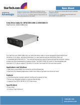
Front
Back
RESET ALARM
Drive Status LEDs
(left column of LEDs)
Power On LED
Channel
Status LED
Power
Supply
Status LED
Fan Status LED
Alarm Reset Button
Drive Activity LEDs
(right column of LEDs)
C
T
R
L
2
C
T
R
L
1
J
P
7
A
D
D
J
U
M
P
E
R
T
O
D
I
S
A
B
L
E
T
E
R
M
I
N
A
T
I
O
N
A
D
D
J
U
M
P
E
R
T
O
S
U
P
P
L
Y
T
E
R
M
P
O
W
E
R
J
P
6
JP5
CNFG 1
CNFG 2
RAID
SPARE 1
SPARE 2
BAUD SEL
DLY STRT
RMT STRT
JP8
A
D
D
J
U
M
P
E
R
T
O
D
I
S
A
B
L
E
T
E
R
M
I
N
A
T
I
O
N
A
D
D
J
U
M
P
E
R
T
O
S
U
P
P
L
Y
T
E
R
M
P
O
W
E
R
C
H
A
N
N
E
L
-
1
C
H
A
N
N
E
L
-
2
JP1
A
DD
JU
M
PE
R
TO
D
ISA
BLE
TER
M
IN
ATI O
N
A
DD
JU
M
PE
R
TO
S
U
PP
LY
TER
M
PO
W
ER
JP3
JP2
JP4
JP1
ADD
JU
M
P
E
R
TO
D
ISAB
LE
TER
M
IN
ATI O
N
A
D
D JUM
PER
TO SU
PPLY
T
ER
M
PO
W
E
R
JP3
JP2
JP4
350-watt hot
swappable independent
power supplies
Dual in-line
80-CFM hot
swappable
cooling fans
SAFTE Disk I/O Card
SAF-TE Service & VT-100 Ports
Controller 2
Controller 1
Controller
Cover Plate
C
hann
el 1
C
hannel 2

5
Components
www.gateway.com
Components
Front bezel
The front bezel houses the status LEDs, drive LEDs, and alarm reset button.
Remove the bezel to access the drives. You can remove and install the bezel
without interrupting current system activities.
Embedded within the front bezel is the electronic package that provides the
communication with the microprocessor. The microprocessor communicates
with SAF-TE processors (SEP) and the drives in the enclosure. It passes
information to the front bezel Channel Mode and drive status LEDs. For more
information on monitoring functions, see “Control and monitoring” on
page 11.
Power is supplied to the front bezel through an edge connector. A control circuit
monitors the bezel for a correct connection. When the bezel is correctly
installed and the storage enclosure is turned on, the bezel is immediately
powered.
For information about removing the bezel, see “Removing the front bezel” on
page 62.
Reset Alarm
Drive LEDs
Alarm Reset Button
Status LEDs

6
Chapter 1: About the Gateway 850 SCSI Storage Enclosure
www.gateway.com
Converting to a dual-backplane device
You can convert the enclosure to a dual-backplane device by removing the
single bus module.
To convert the enclosure into a dual-backplane device:
1 Turn off the enclosure. For instructions, see “Turning off the enclosure”
on page 29.
2 Remove the controller cover plate.
3 Remove the single bus module from the Controller 1 slot.
4 Reinstall the cover plate.
JP7
ADD JUMPER
TO
DISABLE
TERMINATION
ADD JUMPER
TO
SUPPLY
TERM POWER
JP6
J
P
5
C
N
F
G
1
C
N
F
G
2
R
A
I
D
S
P
A
R
E
1
S
P
A
R
E
2
B
A
U
D
S
E
L
D
L
Y
S
T
R
T
R
M
T
S
T
R
T
J
P
8
ADD JUMPER
TO
DISABLE
TERMINATION
ADD JUMPER
TO SUPPLY
TERM POWER
C
H
A
N
N
E
L
-
1
C
H
A
N
N
E
L
-
2
JP1
A
D
D
J
U
M
P
E
R
T
O
D
IS
A
B
L
E
T
E
R
M
IN
A
T
I
O
N
A
D
D
J
U
M
P
E
R
T
O
S
U
P
P
L
Y
T
E
R
M
P
O
W
E
R
JP3
JP2
JP4
JP1
A
D
D
J
U
M
P
E
R
T
O
D
I
S
A
B
L
E
T
E
R
M
IN
A
T
I
O
N
A
D
D
J
U
M
P
E
R
T
O
S
U
P
P
L
Y
T
E
R
M
P
O
W
E
R
JP3
JP2
JP4
Cover Plate
Single-Bus
Module

7
Components
www.gateway.com
AC power
The storage enclosure’s power system consists of two 350-watt, hot-swappable
power supplies, each with independent AC power and cooling fans. This power
system provides the enclosure with “N+1” redundant power. Each power supply
has auto-switching circuitry for use with either 110V or 220V AC systems.
To turn on the enclosure, press each of the two power supply On/Off switches
to the “on” position.
A Power LED on each power supply turns on to indicate that enclosure is turned
on. The front bezel power LED turns green when both power supplies are on
and operating normally. If only one power supply is operational, the front bezel
power LED turns orange.
The power supplies also have a general Fault LED. If the power supply is
installed and the power supply is not receiving power or if the power supply
cooling fan fails, the general power supply Fault LED turns orange and an alarm
sounds.
Each power supply has an AC power cord module. The modules have a power
cord clip incorporated into the design to secure the power cord after it has been
correctly inserted. The clip prevents accidental power cord disconnections.
Blank Plate

8
Chapter 1: About the Gateway 850 SCSI Storage Enclosure
www.gateway.com
Cooling fan module
The cooling system consists of two high-performance (80-CFM) cooling fans
mounted in a single fan module which slides into an open bay at the rear of
the enclosure. The design of the fan module provides an easy user-replaceable
component in a live environment without interruption of service.
If any one fan should fail, cooling redundancy and efficiency are degraded. If
a fan fails, the SAF-TE processor communicates status of the cooling fans, which
turns on the Fan Status LED and an alarm. The SAF-TE processor will also
provide the notification data to any monitoring software.
The enclosure temperature sensors are monitored for out-of-tolerance
conditions of the established temperature threshold value of 60°C (140°F). If
a threshold value is exceeded, the Fan Status LED will begin flashing orange.
The fan module can be replaced during normal operation without turning off
the enclosure or interrupting normal system operations.
Warning Do not operate the enclosure for extended periods of time
(greater than 5 minutes) with the cooling fan module
removed. No enclosure cooling is available while the fans
are removed.

9
Components
www.gateway.com
SAF-TE Disk I/O card
The SAF-TE Disk I/O card provides the built-in environmental and system status
monitoring, as well as host connectivity to the drives. It also houses the
switches for setting SCSI IDs, VT-100 communication protocols, and drive
spinup options.
This card contains two SAF-TE processors (SEPs) that continuously monitor the
enclosure for temperature status, fan status, power supply status, and SCSI
channel status. The SEPs are responsible for reporting environmental conditions
and system status to the front bezel LEDs, audible alarms, external monitoring
software, and third-party monitoring software. Using the SAF-TE specification
protocol version 1.0, the SEPs communicate through the SCSI bus to report on
enclosure status and communicate information about the associated host
system.
At power up, the SAF-TE processors read the SCSI switch settings and configure
the system for the appropriate addresses. They then execute firmware from the
on-board flash memory and perform a self-test. The firmware is flash
upgradeable using the SAF-TE RS-232 Service port located below the I/O card
slots at the rear of the enclosure. The firmware also contains the necessary
functions for enclosure management.
Specific switch settings are discussed later in “Setup and Installation” on
page 13.
Warning The SAF-TE Disk I/O card is not hot swappable. You must
turn off the enclosure prior to removing or replacing this
card.
JP
7
A
D
D
JU
M
P
E
R
T
O
D
IS
A
B
LE
T
E
R
M
IN
A
T
IO
N
JP8
C
NFG 1
CNFG 2
RAID
SPARE 1
SPARE 2
BAU
D SEL
DLY STRT
RM
T ST
RT
A
D
D
JU
M
P
E
R
T
O
D
IS
A
B
LE
T
E
R
M
IN
A
T
IO
N
CHANNEL -1
CHANNEL -2
R
D
A
0
1234 5678
A
1
S
0
S
1
B
D
D
L
R
M
UP (Off -1)
Channel 2
Termination Jumper
Channel 1
Termination Jumper
Channel 1
Channel 2
DOWN (On -0)
Conf
i
gur
a
t
i
on 1
C
o
nf
i
gu
r
a
t
i
on
2
RA
ID
S
p
a
r
e1
S
p
a
r
e
2
B
A
UD Rate
S
elec
t
D
el
a
y
D
r
ive
St
a
r
t
Re
m
ot
e
D
rive St
a
rt

10
Chapter 1: About the Gateway 850 SCSI Storage Enclosure
www.gateway.com
The SAF-TE Disk I/O card has two 68-pin VHD/CI SCSI connectors which
provide the connectivity from the host computer(s) to the drives. The
connectors are labeled “Channel 1” and “Channel 2.”
In JBOD single-bus mode, the Channel 1 connector provides SCSI bus access
to all the drive slots, 1 through 12, and the Channel 2 connector provides the
automatic SCSI bus termination.
In JBOD Dual-Bus mode, the Channel 1 connector provides SCSI bus access to
the drives in slots 7 through 12, and the Channel 2 connector provides access
to the drives in slots 1 through 6. Termination is automatic and provided
internally on the drive mid-plane circuit board.
RS-232 ports
The SAF-TE Service RS-232 serial port is located below the I/O card slots, and
between the two Control ports. The SAF-TE Service port provides an RS-232
serial interface to the SAF-TE Disk I/O card allowing firmware uploads and
maintenance/service monitoring of the SEPs.
CTRL 1
CTRL 2
SAF-TE
SAF-TE Service Port

11
Control and monitoring
www.gateway.com
Control and monitoring
The SAF-TE processors provide monitoring information for the enclosure
environmental conditions such as enclosure temperature, cooling fan status,
power supply status, and SCSI bus status. This information is reported to the
monitoring system to provide the user with LED and audible alarm
notifications. This environmentally monitored information is also
communicated to monitoring software. Refer to “Monitoring Systems” on
page 31 for more complete details.
The enclosure incorporates a “One-Touch Annunciation” which provides an
LED readout of the current switch configuration, host interface type, bus
configuration, communication BAUD setting, drive spin-up settings, and
controller status. For more information, see “One-touch annunciation” on
page 35.
Status indicator LEDs
The Status Indicator LEDs are grouped on the right side of the front bezel
directly above the Alarm Reset button.
Power LED
When the Power LED is green, it indicates that the enclosure is turned on.
Reset Alarm
Drive Status LEDs
(left column of LEDs)
Channel Status LED
Power
Supply
Status LED
Fan Status LED
Alarm Reset Button
Drive Activity LEDs
(right column of LEDs)

12
Chapter 1: About the Gateway 850 SCSI Storage Enclosure
www.gateway.com
Channel Status LED
The Channel Status LED is green at all times.
Power Supply Status LED
The Power Supply Status LED indicates the condition of the power supplies.
The LED is a steady green when both power supplies are functioning normally
and will change to orange if one power supply fails or is turned off.
A failed power supply can be identified by the orange “Fault” LED located on
the power supply.
Fan Status LED
The Fan Status LED indicates the condition of the cooling fans. The LED is green
when both fans are functioning normally. The LED is orange if any of the fans
fail.
Drive LEDs
The Drive LEDs are located on the left side of the front bezel between the
ventilation ribs and comprise the Drive Status LEDs and Drive Activity LEDs.
The Drive LEDs are grouped in pairs and are in the general location of the drive
slot. There are 12 Drive Status and Drive Activity LEDs, one group or pair for
each drive. For detailed information, see “Drive LEDs” on page 33.
Audible alarm
An audible alarm sounds when any of the enclosure’s components change to
an abnormal state. To silence the alarm, press the Alarm Reset button located
on the front bezel. The corresponding alarm’s LED will remain illuminated until
the condition returns to a normal state.

2
13
Setup and
Installation
Overview
This chapter describes the procedures to install and set up
the enclosure. Each section will step you through the
hardware installation, cabling and topology
configurations, and upgrades.
It is important to thoroughly review this information and
perform the procedures in the order in which they are
presented. This will ensure a smooth and trouble-free
installation.

14
Chapter 2: Setup and Installation
www.gateway.com
The installation is divided into three sections:
■ The first section describes installing the enclosure into the rack cabinet.
See “Enclosure detailed installation” on page 15.
■ The second section describes setting the SAF-TE Disk I/O card switches and
the enclosure-to-enclosure cabling. The SAF-TE card switch settings
determine the SCSI IDs, RAID Addressing, and disk spin-up options. See
“Enclosure configuration” on page 21.
■ The third section describes the cabling of the enclosure to the host
system(s). This enclosure is very flexible and there are several possible
configurations. See “Host cabling” on page 28.

15
Enclosure detailed installation
www.gateway.com
Enclosure detailed installation
This first section describes preparing and installing the enclosure into the rack
cabinet.
After installing the hardware components, go to “Enclosure configuration” on
page 21 and set the SAF-TE Disk I/O card switches and enclosure cabling for
your drive configuration.
Installing the storage enclosure in a rack
cabinet
To install the storage enclosure in a rack cabinet:
1 Select an appropriate location within your rack cabinet. If you are installing
more than one enclosure, you should consider the location of the
enclosures in relationship to each other
to make sure that the cables will
easily reach between enclosures.
Make sure that the selected location in the rack cabinet has adequate air
flow for the front-to-side and side-to-side areas.
2 Remove the enclosure from its shipping carton and inspect for obvious
damage. Place the enclosure on a flat surface.
Warning The power supplies and drives should be removed prior
to installing the enclosure into the rack cabinet. The
enclosure chassis could be damaged during installation
due to the added weight of the power supplies and drives.

16
Chapter 2: Setup and Installation
www.gateway.com
3 Rotate the front bezel thumbscrews counter-clockwise one-quarter turn to
unlock the bezel.
4 Using both hands, grasp and pull the front bezel away from the enclosure.
Store the bezel in a location so that it will not be damaged.
5 Remove each of the power supplies by grasping each handle and pressing
in on the release latch with your thumb as you pull the power supply away
from the enclosure.
6 Remove each of the drives.
R
eset Alarm
R
e
s
e
t A
la
rm
/