Page is loading ...

componentguide
Hard Drive Installation
Installing
Configuring
Your Gateway Computer


i
Contents
1 Preparing for Installation . . . . . . . . . . . . . . . . . . . . . . . . . . . . . . . . . . . . . . . . 1
Preventing static electricity discharge . . . . . . . . . . . . . . . . . . . . . . . . . . . . . . . . . . . . 4
2 Removing an Existing Drive . . . . . . . . . . . . . . . . . . . . . . . . . . . . . . . . . . . . . 5
3 Configuring the New Drive. . . . . . . . . . . . . . . . . . . . . . . . . . . . . . . . . . . . . . . 9
Configuring the new IDE drive . . . . . . . . . . . . . . . . . . . . . . . . . . . . . . . . . . . . . . . . 10
Setting the IDE jumpers . . . . . . . . . . . . . . . . . . . . . . . . . . . . . . . . . . . . . . . . . . 12
Configuring the new SCSI drive . . . . . . . . . . . . . . . . . . . . . . . . . . . . . . . . . . . . . . . 14
Setting the SCSI jumpers . . . . . . . . . . . . . . . . . . . . . . . . . . . . . . . . . . . . . . . . . 16
Configuring the new Serial ATA drive . . . . . . . . . . . . . . . . . . . . . . . . . . . . . . . . . . . 19
4 Installing the New Drive. . . . . . . . . . . . . . . . . . . . . . . . . . . . . . . . . . . . . . . . . 21
Installing the drive in your computer . . . . . . . . . . . . . . . . . . . . . . . . . . . . . . . . . . . . 22
Installing the additional fan . . . . . . . . . . . . . . . . . . . . . . . . . . . . . . . . . . . . . . . . . . . 26
Connecting the drive cables . . . . . . . . . . . . . . . . . . . . . . . . . . . . . . . . . . . . . . . . . . 28
5 Setting Up the New Drive Automatically . . . . . . . . . . . . . . . . . . . . . . . . 35
Setting up the hard drive . . . . . . . . . . . . . . . . . . . . . . . . . . . . . . . . . . . . . . . . . . . . . 36
Using the red Drivers CD . . . . . . . . . . . . . . . . . . . . . . . . . . . . . . . . . . . . . . . . . 36
Using the System Restoration Kit . . . . . . . . . . . . . . . . . . . . . . . . . . . . . . . . . . . 38
Using the System Restoration CD . . . . . . . . . . . . . . . . . . . . . . . . . . . . . . . . . . 39
6 Setting up the New Drive Manually . . . . . . . . . . . . . . . . . . . . . . . . . . . . . 41
Partitioning the new drive . . . . . . . . . . . . . . . . . . . . . . . . . . . . . . . . . . . . . . . . . . . . 41
Determining which file system to use . . . . . . . . . . . . . . . . . . . . . . . . . . . . . . . . 42
Creating a primary partition . . . . . . . . . . . . . . . . . . . . . . . . . . . . . . . . . . . . . . . 43
Creating the extended partition . . . . . . . . . . . . . . . . . . . . . . . . . . . . . . . . . . . . 46
Creating an NTFS partition in Windows NT 4.0 . . . . . . . . . . . . . . . . . . . . . . . . 47
Creating an NTFS partition in Windows XP . . . . . . . . . . . . . . . . . . . . . . . . . . . 48
Formatting the New Drive . . . . . . . . . . . . . . . . . . . . . . . . . . . . . . . . . . . . . . . . . . . . 50
Formatting a primary partition using DOS . . . . . . . . . . . . . . . . . . . . . . . . . . . . 50
Formatting a partition or slave drive using Windows . . . . . . . . . . . . . . . . . . . . 52
7 Troubleshooting . . . . . . . . . . . . . . . . . . . . . . . . . . . . . . . . . . . . . . . . . . . . . . . . 53
A Safety, Regulatory, and Legal Information . . . . . . . . . . . . . . . . . . . . . . 55

ii

1
1
Preparing for
Installation
This guide provides the information you need to install a
replacement or new hard drive. This guide covers SCSI and
IDE hard drives.
Installing a hard drive is a process consisting of seven
procedures that must be done in sequence:
1 Prepare for installation.
2 Remove an existing drive (if applicable).
3 Set the jumpers on the new drive (if applicable).
4 Install the new drive.
5 Set up the new drive.
6 Partition the new drive (manual setup).
7 Format the new drive (manual setup).

2
Chapter 1: Preparing for Installation
www.gateway.com
This guide also has a troubleshooting section that provides hard drive
installation troubleshooting tips.
See the documentation that came with your computer for information about
opening and closing your computer case.
To prepare for installation:
1 Find a place to install the new hardware that:
■ Is clean. (Avoid dusty areas.)
■ Is a low-static environment. (Avoid carpeted areas.)
■ Has a stable platform on which to set your computer.
■ Is near a telephone in case you need technical support assistance from
Gateway Technical Support. The telephone must be directly connected
to a telephone jack and cannot be connected to your computer.
Important The illustrations in this document show a typical computer.
They may not exactly match your configuration and may
include options you did not purchase. However, they are
similar enough to your computer that they should help you
install your drive successfully.

3
www.gateway.com
2 Obtain these additional items:
■ A Phillips screwdriver.
■ A grounding wrist strap (available at most electronic stores).
■ The red Drivers CD, System Restoration Kit, or System Restoration CD that
came with your computer.
■ A small container to hold hardware parts, such as screws, while you
are working.
■ The documentation that came with your computer.
3 If you are replacing a working hard drive, back up any files that you want
to save.
4 Determine which operating system your computer uses by right-clicking
the
My Computer icon (located on the Desktop or the Start menu), then
clicking
Properties. The name and version of your operating system are
listed on the General tab of the System Properties dialog box. You will need
this information to partition the hard drive.
Important If you do not have printed documentation, go to the
Gateway Web site (www.support.gateway.com
) and print the
appropriate document before starting the installation procedure.

4
Chapter 1: Preparing for Installation
www.gateway.com
Preventing static electricity
discharge
The components inside your computer are extremely sensitive to static
electricity, also known as electrostatic discharge (ESD).
Before opening your computer case, follow these guidelines:
■ Turn off your computer power.
■ Wear a grounding wrist strap (available at most electronics stores) and
attach it to a bare metal part of your computer.
■ Touch a bare metal surface on the back of your computer.
■ Unplug the power cord and modem cable.
Before working with computer components, follow these guidelines:
■ Avoid static-causing surfaces such as carpeted floors, plastic, and packing
foam.
■ Remove components from their antistatic bags only when you are ready
to use them. Do not lay components on the outside of antistatic bags
because only the inside of the bags provide electrostatic protection.
■ Always hold expansion cards by their edges or their metal mounting
brackets. Avoid touching the edge connectors and components on the
cards. Never slide expansion cards or components over any surface.
Warning ESD can permanently damage electrostatic discharge
sensitive components in your computer. Follow the ESD
guidelines every time you open your computer case to
prevent ESD damage.
Warning To avoid exposure to dangerous electrical voltages and
moving parts, turn off your computer and unplug the power
cord and modem cable before opening the case.
Warning To prevent risk of electric shock, do not insert any object
into the vent holes of the power supply.

2
5
Removing an
Existing Drive
Follow this procedure only if you are replacing an existing
hard drive. If you are adding a new hard drive, go to
“Configuring the New Drive” on page 9.
Warning Avoid exposure to dangerous electrical
voltages and moving parts by turning off your
computer and unplugging the power cord
and modem cable before opening the case.
Tips & Tricks See the documentation that came with your
computer for more information about your
specific computer case.
Tips & Tricks If you are replacing a drive, make note of the
jumper settings on the old drive so you can
configure the new drive the same way.

6
Chapter 2: Removing an Existing Drive
www.gateway.com
To remove an existing drive:
1 Turn off your computer, then disconnect the power cord and external
cables.
See the documentation that came with your computer for instructions on
removing your computer case cover.
2 Following the static electricity precautions on page 4, remove your
computer case cover.s
3 Remove the data ribbon cable (IDE or SCSI drives) or signal cable (Serial
ATA drive) and power cable from the back of the hard drive.

7
www.gateway.com
4 If the drive is mounted to a removable cage or brackets, remove the cage
or brackets from your computer case, then remove the drive from the cage
or brackets.
- OR -

8
Chapter 2: Removing an Existing Drive
www.gateway.com
If the drive is attached to a fixed cage, slide the release lever, then remove
the drive.
5 If this drive is a replacement for a failed drive, carefully pack the failed
drive and follow the instructions on the return form to send your drive
back to Gateway for credit.
Go to “Configuring the New Drive” on page 9.

3
9
Configuring the
New Drive
Read this chapter to learn about:
■ Cabling and configuring IDE drives for master or slave
■ Cabling and configuring SCSI drives for ID and
termination
■ Cabling and configuring Serial ATA drives

10
Chapter 3: Configuring the New Drive
www.gateway.com
Configuring the new IDE drive
If your new drive is a SCSI drive, go to “Configuring the new SCSI drive” on
page 14.
If your new drive is a Serial ATA drive, go to “Configuring the new Serial ATA
drive” on page 19.
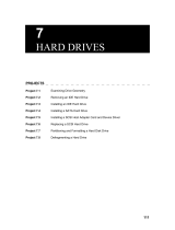
Your system board may contain as many as three controllers (where the wide
ribbon cables attach to the main system board or a host adapter add-in card).
One controller is for the diskette drive. Two are for IDE drives. One of the IDE
controllers is the primary controller and the other is the secondary controller.
Each IDE controller can contain two devices, a master device and a slave device.
To I D E
controller
Slave
drive
Master
drive

11
Configuring the new IDE drive
www.gateway.com
Master drives
If the drive you are installing is on the end of the cable, it is the master drive.
Master drives are typically bootable, which means they are used to boot, or start,
your computer.
Your IDE drive should be configured as a master if it will be the only drive
connected to the IDE interface cable or if there will be two drives connected
to the cable and the other drive is configured as a slave.
Slave drives
If the drive you are installing is in the middle of the cable, it is the slave drive.
Slave drives are typically used for storing files and installing programs. You
cannot start your computer from the slave drive.
A slave drive is the secondary drive on either the primary or secondary IDE
controller. Configure your IDE drive as a slave drive if the drive will be one of
two drives connected to the IDE interface cable and the other drive is configured
as a master drive.
If there is already one drive connected to the cable before the new IDE drive
is installed, it is probably configured as a master. However, some IDE drives
require a different master or slave setting when two drives are connected. If
you have any problems, see the documentation that came with the existing
IDE drive for additional master or slave configuration information.
Cable select
Cable select is a jumper setting that configures the drive as a master or slave
drive based on its position on the IDE cable. If both drives on the IDE data
cable are configured as cable select, the middle drive is the slave and the end
drive is the master.
The drive and the IDE data cable must support cable select to use this option.
Important If you have only one drive, it must be connected to the end
connector on the IDE cable.
Important If you are adding a drive and making it the master (boot)
drive, the existing drive must be reconfigured as a slave
drive.

12
Chapter 3: Configuring the New Drive
www.gateway.com
Setting the IDE jumpers
IDE drives contain a jumper block. A jumper block is a set of pins located on
the drive. The jumper block is typically located on the rear of the drive,
although it may be located on the top or the bottom of the drive.
On some IDE drives, a jumper is placed over two of the pins to configure the
drive as the master (or single) drive or as the slave drive. IDE drives are labeled
with information about which set of pins must be used to make the drive a
master or slave.
Other IDE drives use the cable select setting to configure the drive. Cable select
is a jumper setting that configures the drive as a master or slave drive based
on its position on the IDE cable. If both drives on the IDE data cable are
configured as cable select, the middle drive is the slave and the end drive is
the master. The drive and the IDE data cable must support cable select.

13
Configuring the new IDE drive
www.gateway.com
Usually, if you are installing the new drive as a replacement drive, configure
the new drive settings so they match your old drive settings. If your old drive
was set as a master drive, set the new drive as a master drive.
However, in order to maintain the same configuration (master, slave, or cable
select), your new drive may require different jumper settings than your current
drive. Check the label on your drive for the correct settings.
To set the jumpers for an IDE drive:
1 Find the jumpers for setting a master, a slave, or a cable select drive by
looking at the jumper label. The label is either a sticker on the drive, or
it is printed directly on the drive.
2 If both of the drives and the IDE data cable support cable select, set the
jumpers for the drives as cable select. IDE data cables that support cable
select should be labeled
CS. Cable select makes the drive in the middle of
the cable the slave and the drive at the end of the cable the master. Go
to “Installing the New Drive” on page 21.
- OR -
If either the drives or the IDE data cable do not support cable select, go
to the next step.
3 If the drive is in the middle of the IDE data cable and you are going to
configure your drive as the slave drive, set the jumpers as Slave A. If Slave A
is not an option, set the jumpers as Slave. Go to “Installing the New Drive”
on page 21.
- OR -
If the drive is at the end of the IDE data cable and you are going to
configure your drive as the master drive, set the jumpers as Master A. If
Master A is not an option, set the jumpers as Master. Go to “Installing the
New Drive” on page 21.

14
Chapter 3: Configuring the New Drive
www.gateway.com
Configuring the new SCSI drive
If your new drive is an IDE drive, go to “Configuring the new IDE drive” on
page 10.
If your new drive is a Serial ATA drive, go to “Configuring the new Serial ATA
drive” on page 19.
If your computer contains SCSI devices, they are connected to a SCSI host
adapter add-in card.
All devices on a SCSI data ribbon cable connect to form a chain. This chain
contains a SCSI host adapter and your other SCSI devices such as the hard drive
and tape backup unit.
To configure SCSI devices correctly on the SCSI chain, you must designate
(terminate) the ends of the chain and determine the order of the links (IDs)
between the ends of the SCSI chain.
Host
adapter
SCSI data
ribbon cable
Last SCSI device
(ID = 0, Terminator = ON)
Additional SCSI device
(ID = 1, Terminator = OFF)

15
Configuring the new SCSI drive
www.gateway.com
Termination
Each device on the SCSI cable is either at an end of the chain or at a link in
the middle. A SCSI device has a terminator jumper which can be set to On (for
a device at the end of the chain) or Off (for devices in the middle of the chain).
Generally, your computer’s SCSI host adapter is at one end of the chain and a
terminated device is at the other. All other devices are middle links. The SCSI
host adapter can be set so you can start up from any device on the SCSI chain.
SCSI IDs
In addition to recognizing the ends of the SCSI chain, your computer needs
to designate the order of the links. For this reason, each device on the SCSI
chain requires a unique device ID. This ID can be any number between 0 and 15
(for Ultra Wide SCSI) other than 7, which is the factory preset for the host
adapter. The ID number, or address, is set on most SCSI devices by adjusting
jumpers on pins.

16
Chapter 3: Configuring the New Drive
www.gateway.com
Setting the SCSI jumpers
SCSI drives contain a jumper block. A jumper block is a set of pins located on
the drive. The jumper block is typically located on the rear of the drive,
although it may be located on the top or the bottom of the drive.
On SCSI drives, a jumper is placed over two of the pins to configure the SCSI
drive’s termination setting. Other jumpers are placed over additional sets of pins
to configure the ID setting.
/