Page is loading ...

Intel Confidential
Intel
®
Server Platform
SR6850HW4
Technical Product Specification
Intel order number D23151-001
Revision 1.0
May, 2005
Enterprise Platforms and Services Division – Marketing

Revision History Intel® Server Platform SR6850HW4 TPS
Revision 1.0
Intel order number D23151-001
ii
Revision History
Date Revision
Number
Modifications
May 2005 1.0 Initial release.
Disclaimers
Information in this document is provided in connection with Intel
®
products. No license, express
or implied, by estoppel or otherwise, to any intellectual property rights is granted by this
document. Except as provided in Intel's Terms and Conditions of Sale for such products, Intel
assumes no liability whatsoever, and Intel disclaims any express or implied warranty, relating to
sale and/or use of Intel products including liability or warranties relating to fitness for a particular
purpose, merchantability, or infringement of any patent, copyright or other intellectual property
right. Intel products are not intended for use in medical, life saving, or life sustaining
applications. Intel may make changes to specifications and product descriptions at any time,
without notice.
Designers must not rely on the absence or characteristics of any features or instructions marked
“reserved” inches or “undefined” Intel reserves these for future definition and shall have no
responsibility whatsoever for conflicts or incompatibilities arising from future changes to them.
This document contains information on products in the design phase of development. Do not
finalize a design with this information. Revised information will be published when the product
is available. Verify with your local sales office that you have the latest datasheet before
finalizing a design.
The Intel® Server Platform SR6850HW4 may contain design defects or errors known as errata,
which may cause the product to deviate from published specifications. Current characterized
errata are available on request.
Intel Corporation server baseboards contain a number of high-density VLSI and power delivery
components that need adequate airflow to cool. Intel’s own chassis are designed and tested to
meet the intended thermal requirements of these components when the fully integrated system
is used together. It is the responsibility of the system integrator that chooses not to use Intel
developed server building blocks to consult vendor datasheets and operating parameters to
determine the amount of airflow required for their specific application and environmental
conditions. Intel Corporation cannot be held responsible if components fail or the server board
does not operate correctly when used outside any of their published operating or non-operating
limits.
Intel and Xeon are trademarks or registered trademarks of Intel Corporation.
*Other brands and names may be claimed as the property of others.
Copyright © Intel Corporation 2005.

Intel® Server Platform SR6850HW4 TPS Table of Contents
Revision 1.0
Intel order number D23151-001
iii
Table of Contents
1. Product Overview.................................................................................................................1
2. System Overview..................................................................................................................3
2.1 System Feature Overview........................................................................................ 3
2.2 Introduction .............................................................................................................. 4
2.3 External Chassis Features - Front ........................................................................... 8
2.3.1 Front Control Panel.................................................................................................. 8
2.3.2 Hot-swap Hard Disk Drive and Peripheral Device Bays .......................................... 9
2.4 External Chassis Features - Rear.......................................................................... 10
2.5 Internal Chassis Features...................................................................................... 11
2.5.1 Server Board Set SE8500HW4 Mainboard............................................................ 11
2.5.2 Server Board Set SE8500HW4 Memory Board ..................................................... 12
2.5.3 Power Distribution Board ....................................................................................... 12
2.5.4 SCSI Backplane Board Board ...............................................................................12
2.5.5 Front Panel I/O Board............................................................................................ 13
2.5.6 Front Panel Control Board ..................................................................................... 13
2.5.7 SATA-to-IDE Converter Board............................................................................... 13
2.5.8 Intel® Management Module................................................................................... 13
2.5.9 Fibre Channel Module ...........................................................................................14
2.5.10 RAID On Motherboard (ROMB) ............................................................................. 14
2.5.11 Power Supply Module............................................................................................ 14
2.5.12 Cooling Subsystem................................................................................................ 16
2.6 New Platform Features ..........................................................................................16
2.6.1 Advanced Memory Performance and Protection ................................................... 16
2.6.2 Rolling BIOS .......................................................................................................... 17
2.7 Server Management .............................................................................................. 17
2.7.1 Intel Management Module (IMM)........................................................................... 17
2.7.2 Hot Swap Controller............................................................................................... 19
2.8 Reliability, Availability, Serviceability, Usability, Manageability (RASUM) ............. 19
2.9 Expansion Support ................................................................................................20
2.10 Specifications......................................................................................................... 21
2.10.1 Environmental Specifications Summary ................................................................ 21
2.10.2 Physical Specifications .......................................................................................... 22

Table of Contents Intel® Server Platform SR6850HW4 TPS
Revision 1.0
Intel order number D23151-001
iv
3. Server System Chassis and Assemblies .........................................................................23
3.1 Chassis, Rails and Top Cover ............................................................................... 23
3.1.1 Chassis .................................................................................................................. 23
3.1.2 Slide Rails.............................................................................................................. 25
3.1.3 Top Cover .............................................................................................................. 25
3.2 Power and Fans..................................................................................................... 25
3.3 Fan Subsystem...................................................................................................... 26
3.4 Mainboard Assembly ............................................................................................. 26
3.5 Peripheral Bay and Front Panel............................................................................. 27
3.5.1 Hot-Swap Hard Disk Drive Carrier......................................................................... 27
3.5.2 Optical Drive Carrier .............................................................................................. 28
3.5.3 Front Panel ............................................................................................................ 29
3.6 Front Bezel ............................................................................................................ 30
4. Cables and Connectors .....................................................................................................31
4.1 Cable and System Interconnect Descriptions........................................................ 33
4.2 User-accessible I/O Connectors ............................................................................ 35
4.2.1 Video Connectors .................................................................................................. 35
4.2.2 USB 2.0 Connectors .............................................................................................. 36
4.2.3 Etherent Connectors.............................................................................................. 37
4.2.4 External 68-pin Ultra320 SCSI VHDCI Connector................................................. 39
4.2.5 Internal 68-pin SCSI Connectors ........................................................................... 40
4.2.6 80-pin SCA2 Hard Disk Drive Connectors............................................................. 41
4.2.7 AC Power Input Connectors .................................................................................. 42
4.2.8 3-pin Chassis Intrusion Connector......................................................................... 42
4.2.9 12-pin Power Distribution Board Power Connector ............................................... 42
4.2.10 30-pin Power Distribution Board to Mainboard Connector .................................... 43
4.2.11 30-pin SCSI Backplane Board Board to Front Panel I/O Board Connector........... 43
4.2.12 100-pin Mainboard to SCSI Backplane Board Board Connector........................... 44
4.2.13 Peripheral Power Connector.................................................................................. 45
4.2.14 Fan Connectors ..................................................................................................... 46
4.2.15 50-pin Front Panel Control Module Connector ...................................................... 47
4.2.16 SATA-to-IDE Converter Board Connector ............................................................. 48
4.2.17 SATA-to-IDE Converter Board Power Connector .................................................. 48
4.2.18 SATA Connector.................................................................................................... 49
5. Power Supply......................................................................................................................51

Intel® Server Platform SR6850HW4 TPS Table of Contents
Revision 1.0
Intel order number D23151-001
v
5.1 Mechanical Outline ................................................................................................ 52
5.2 Power Supply Output Interface.............................................................................. 54
5.2.1 Blade Connector .................................................................................................... 54
5.3 AC Input Requirement ........................................................................................... 55
5.3.1 AC Input Voltage Specification .............................................................................. 55
5.3.2 Efficiency ............................................................................................................... 55
5.3.3 Input Over-Current Protection................................................................................ 55
5.3.4 Inrush Current........................................................................................................ 55
5.3.5 Auto Restart........................................................................................................... 56
5.3.6 Power Factor Correction (PFC) ............................................................................. 56
5.3.7 AC Input Connector ............................................................................................... 56
5.4 DC Output Requirements ...................................................................................... 56
5.4.1 Hot Swap Functionality .......................................................................................... 57
5.4.2 Output Current Rating............................................................................................ 57
5.4.3 Over- and Under-Voltage Protection ..................................................................... 57
5.4.4 Over-current Protection .........................................................................................58
5.4.5 Short Circuit Protection.......................................................................................... 58
5.4.6 Reset After Shutdown............................................................................................ 58
5.4.7 Current Sharing .....................................................................................................59
5.4.8 I
2
C Devices ............................................................................................................ 59
5.4.9 Fan Speed Control................................................................................................. 61
5.4.10 Power Supply Module LED indicators ................................................................... 61
6. Power Distribution Board..................................................................................................63
6.1 Introduction ............................................................................................................ 63
6.2 Signal Descriptions and Pinouts ............................................................................ 65
6.2.1 Remote On/Off (-PS_ON)...................................................................................... 66
6.2.2 Power Good Signal (POK or P_GOOD) ................................................................66
6.2.3 VIN_GOOD............................................................................................................ 66
7. SCSI Backplane Board.......................................................................................................67
7.1 Introduction ............................................................................................................ 67
7.1.1 Block Diagram ....................................................................................................... 67
7.1.2 Architectural Overview........................................................................................... 68
7.1.3 Mechanical Specifcations ...................................................................................... 70
7.1.4 Component Location.............................................................................................. 71
7.2 Functional Architecture .......................................................................................... 73

Table of Contents Intel® Server Platform SR6850HW4 TPS
Revision 1.0
Intel order number D23151-001
vi
7.2.1 SCSI Buses ...........................................................................................................73
7.2.2 SCSI Drive Power Control ..................................................................................... 73
7.2.3 SCSI Enclosure Management ............................................................................... 75
7.2.4 Server Management Interface ............................................................................... 76
7.2.5 Resets.................................................................................................................... 77
7.2.6 Connector Interlocks.............................................................................................. 77
7.2.7 Clock Generation ................................................................................................... 77
7.2.8 Programmed Devices ............................................................................................ 78
7.3 Signal Descriptions ................................................................................................ 78
7.3.1 Power from the Power Distribution Board.............................................................. 79
7.3.2 Front Panel Power Connector ...............................................................................79
7.3.3 Front Panel I/O Board Ribbon Cable Connector ................................................... 79
7.3.4 LVD SCSI 68-pin Connector.................................................................................. 80
7.3.5 SCA2 80-pin Drive Connectors.............................................................................. 81
7.3.6 Fans....................................................................................................................... 82
7.3.7 Internal Logic Signals ............................................................................................ 82
7.4 Electrical, Environmental, and Mechanical Specifications..................................... 83
7.4.1 Electrical Specifications ......................................................................................... 83
8. Front Panel I/O and Control Boards .................................................................................85
8.1 Introduction ............................................................................................................ 85
8.1.1 Block Diagram ....................................................................................................... 85
8.1.2 Architectural Overview........................................................................................... 86
8.1.3 Component Location.............................................................................................. 87
8.2 Functional Architecture .......................................................................................... 88
8.2.1 VGA ....................................................................................................................... 88
8.2.2 USB ....................................................................................................................... 88
8.2.3 NMI Button............................................................................................................. 88
8.3 Signal Descriptions ................................................................................................ 89
8.3.1 USB Connector...................................................................................................... 89
8.3.2 Front Panel VGA Connector ..................................................................................90
8.4 Electrical, Environmental, and Mechanical Specifications..................................... 90
8.4.1 Electrical Specifications ......................................................................................... 90
8.4.2 Connector Specifications ....................................................................................... 91
8.4.3 Cooling Requirements ........................................................................................... 91
8.5 Front Panel Control Module................................................................................... 92

Intel® Server Platform SR6850HW4 TPS Table of Contents
Revision 1.0
Intel order number D23151-001
vii
8.5.1 Button Control Panel.............................................................................................. 92
8.5.2 Intel
®
Local Control Panel...................................................................................... 94
8.5.3 System ID Buttons and LEDs ................................................................................ 95
9. SATA-to-IDE Converter Board...........................................................................................97
9.1 Mechanical Outline ................................................................................................ 97
10. Regulatory Specifications .................................................................................................99
10.1 Important Safety Information ................................................................................. 99
10.2 Intended Application Uses ..................................................................................... 99
10.3 Product Safety ....................................................................................................... 99
10.4 Electromagnetic Compatibility (EMC) – Emissions and Immunity ......................... 99
10.5 Certifications / Registrations / Declarations ......................................................... 100
10.6 Regulatory Compliance Markings........................................................................ 101
10.7 Regional EMC Compliance Notices/Information.................................................. 102
Glossary...................................................................................................................................105
Reference Documents............................................................................................................107

List of Figures Intel® Server Platform SR6850HW4 TPS
Revision 1.0
Intel order number D23151-001
viii
List of Figures
Figure 1. Intel
®
Server Platform SR6850HW4, Bezel Removed .................................................. 4
Figure 2. Server Platform SR6850HW4, Bezel and Pedestal Conversion Kit Installed ............... 5
Figure 3. Server Platform SR6850HW4, Rear View with Top Cover Removed........................... 6
Figure 4. Server Platform SR6850HW4 Chassis Block Diagram................................................ 7
Figure 5. Rear View of the Server Platform SR6850HW4 ........................................................ 10
Figure 6. Server Platform SR6850HW4 Rack and Pedestal Configurations ............................. 24
Figure 7. Server Platform SR6850HW4, Bezel and Top Cover Removed................................ 24
Figure 8. Rear of Server Platform SR6850HW4, Power Supplies Installed.............................. 25
Figure 9. System Fan................................................................................................................. 26
Figure 10. Mainboard and Sheet Metal Tray, Assembly............................................................ 27
Figure 11. Hot-Swap Hard Drive Carrier.................................................................................... 28
Figure 12. Optical Drive Carrier with SATA-to-IDE Converter Board......................................... 28
Figure 13. Front Panel with Button Control Panel...................................................................... 29
Figure 14. Front Panel with Intel
®
Local Control Panel .............................................................. 29
Figure 15. Front Bezels (Rack and Pedestal) ............................................................................ 30
Figure 16. Server Platform SR6850HW4 Interconnect Diagram............................................... 32
Figure 17. Dual Stacked Ethernet Connector ............................................................................ 38
Figure 18. 68-Pin SCSI Connector Non-Shielded...................................................................... 40
Figure 19. SCA2 80-Pin SCSI Connector ..................................................................................41
Figure 20. AC Power Input Connector ....................................................................................... 42
Figure 21. 1570W Power Supply ............................................................................................... 51
Figure 22. Power Supply Mechanical Specification ................................................................... 53
Figure 23. Power Supply Signal Sharing ................................................................................... 63
Figure 24. Power Distribution Board Layout .............................................................................. 64
Figure 25. Power Distribution Board to Power Supply Module Docking Connector Signals...... 65
Figure 26. Mainboard Connector Signals .................................................................................. 66
Figure 27. Server Platform SR6850HW4 SCSI Backplane Board Board Block Diagram ......... 68
Figure 28. SCSI Backplane Board Board Component Placement (Primary Side) ..................... 70
Figure 29. SCSI Backplane Board Board Component Placement (Primary Side) ..................... 71
Figure 30. SCSI Backplane Board Board Component Placement (Secondary Side) ................ 72
Figure 31. Enclosure Management Signal Flow Diagram.......................................................... 75
Figure 32. Front Panel I/O Board Block Diagram ......................................................................86

Intel® Server Platform SR6850HW4 TPS List of Figures
Revision 1.0
Intel order number D23151-001
ix
Figure 33. Front Panel I/O Board Placement Diagram .............................................................. 87
Figure 34. Front Panel I/O Board...............................................................................................88
Figure 35. Button Control Panel Features ................................................................................. 92
Figure 36. Local Control Panel Features ................................................................................... 95
Figure 37. SATA-to-IDE Converter Board Mechanical Outline .................................................. 97
Figure 38. SATA-to-IDE Converter Board.................................................................................. 97
Figure 39. SATA-to-IDE Converter Board with Attached Optical Drive...................................... 98
Figure 40. SATA-to-IDE Converter Board with Attached Optical Drive...................................... 98

List of Tables Intel® Server Platform SR6850HW4 TPS
Revision 1.0
Intel order number D23151-001
x
List of Tables
Table 1. Intel
®
Server Platform SR6850HW4 Feature List........................................................... 3
Table 2. Front View of the Server Platform SR6850HW4, Bezel Removed................................. 8
Table 3. System Power Budget .................................................................................................15
Table 4. Expansion Support....................................................................................................... 20
Table 5. Environmental Specifications Summary ......................................................................21
Table 6. Physical Specifications ................................................................................................ 22
Table 7. Cable Descriptions.......................................................................................................33
Table 8. Connector Descriptions................................................................................................33
Table 9. Video Connector Pinout ............................................................................................... 35
Table 10. Dual USB Connector Pinout .....................................................................................36
Table 11. TaDual Ethernet Stacked Connector ......................................................................... 37
Table 12. Server Management Ethernet Connector .................................................................. 38
Table 13. Ultra320 SCSI VHDCI Connector Pinout ................................................................... 39
Table 14. 68-Pin SCSI Connector Pinout ..................................................................................40
Table 15. SCA2 Drive Connector Pinout ...................................................................................41
Table 16. 3-pin Chassis Intrusion Connector............................................................................. 42
Table 17. Power Connector Pinout ............................................................................................ 42
Table 18. 30-pin Power Distribution Board to Mainboard Connector......................................... 43
Table 19. Front Panel I/O Board Connector Signal Description ................................................43
Table 20. 100-pin Connector Pinout (Unused and Ground) ......................................................44
Table 21. 100-pin Connector Pinout (Signals) ........................................................................... 44
Table 22. Peripheral Power Connector...................................................................................... 45
Table 23. 12-pin Fan Power and Control ................................................................................... 46
Table 24. 24-pin Fan Power and Control J6E1.......................................................................... 46
Table 25. Front Panel Control Module Connector Signal Description .......................................47
Table 26. SATA-to-IDE Converter Board Connector ................................................................. 48
Table 27. SATA-To-IDE Converter Board Power Connector..................................................... 48
Table 28. SATA Signal Connector ............................................................................................. 49
Table 29. PowerBlade Pin Assignment...................................................................................... 54
Table 30. AC Input Rating.......................................................................................................... 55
Table 31. DC Output Voltage Regulation Limits ........................................................................ 56
Table 32. 1570W Load Ratings ................................................................................................. 57

Intel® Server Platform SR6850HW4 TPS List of Tables
Revision 1.0
Intel order number D23151-001
xi
Table 33. Over- and Under-voltage Limits .................................................................................57
Table 34. Over-current Protection Limits ................................................................................... 58
Table 35. Output Current Sharing.............................................................................................. 59
Table 36. I/O Port Expander Signals .........................................................................................60
Table 37. I/O Port Expander Codes........................................................................................... 60
Table 38. Power Supply Fan Voltage ........................................................................................61
Table 39. Hot-swap SCSI Hard Disk Drive LED Details ............................................................ 74
Table 40. I
2
C Local Bus Addresses ........................................................................................... 76
Table 41. Global I
2
C Bus Addresses (IPMB Bus) ...................................................................... 77
Table 42. I
2
C IO Bus Address .................................................................................................... 77
Table 43. Power Interface Signals ............................................................................................. 79
Table 44. Front Panel I/O Board Power Interface Signals ......................................................... 79
Table 45. Front Panel I/O Board Ribbon Connector Signal Description .................................... 79
Table 46. LVD SCSI Connector Signal Description ................................................................... 80
Table 47. .LVD SCSI Bus Signals.............................................................................................. 81
Table 48. Internal Logic Signals................................................................................................. 82
Table 49. Electrical Specifications ............................................................................................. 83
Table 50. Maximum Power Consumption .................................................................................. 83
Table 51. SCSI Backplane Board Board Power Limits per Drive .............................................. 84
Table 52. DC Voltage Regulation .............................................................................................. 84
Table 53. USB Connector .......................................................................................................... 89
Table 54. VGA Connector Signal Description............................................................................ 90
Table 55. Electrical Specifications ............................................................................................. 90
Table 56. Maximum Power Consumption .................................................................................. 91
Table 57. DC Voltage Regulation .............................................................................................. 91
Table 58. Server Platform SR6850HW4 Front Panel I/O Board Connector Specifications ...... 91
Table 59. Button Control Panel Details...................................................................................... 92
Table 60. System ID LED Details ..............................................................................................95
Table 61. Product Regulatory Compliance Markings............................................................... 101
Table 62. Regional EMC Compliance Information................................................................... 102

List of Tables Intel® Server Platform SR6850HW4 TPS
Revision 1.0
Intel order number D23151-001
xii
< This page intentionally left blank. >

Intel® Server Platform SR6850HW4 TPS Product Overview
Revision 1.0
Intel order number D23151-001
1
1. Product Overview
This product specification details the features of the Intel
®
Server Platform SR6850HW4.
Reliability, low cost, time to market, modularity, high performance, and management features
are primary considerations in the design.
The Server Platform SR6850HW4 supports up to four 64-bit Intel
®
Xeon™ Processors MP with
up to 8MB L3 cache and incorporates features that clearly differentiate it as a high availability
server. Building on previous server platforms, the Server Platform SR6850HW4 introduces
redundant memory and networking in addition to the enterprise features of hot-swap power,
cooling, PCI slots, and hard disk drives. Advanced server management features are also
included to remotely monitor and manage the server. Finally, the server has two optional mass
storage expansion features.
This document is organized into ten chapters:
Chapter 1: Introduction
An overview of this document.
Chapter 2: System Overview
An overview of the system hardware.
Chapter 3: System Chassis and Sub-Assemblies
An overview of the chassis and major sub-assemblies.
Chapter 4: Cables and Connectors
Describes the cables and connectors specific to the Server Platform SR6850HW4.
Chapter 5: Power Supply
Describes the power supplies used in the Server Platform SR6850HW4.
Chapter 6: Power Distribution Board
Describes the Power Distribution Board used in the Server Platform SR6850HW4 and
Intel
®
Server Platform SR4850HW4.
Chapter 7: SCSI Backplane Board
Describes the SCSI Backplane Board used in the Server Platform SR6850HW4.
Chapter 8: Front Panel I/O and Control Boards
Describes the Front Panel I/O Board and Control Boards used in the Server Platform
SR6850HW4.
Chapter 9: SATA-to-IDE Converter Boards
Describes the SATA-to-IDE Converter Board used in the Server Platform SR4850HW4
and Server Platform SR6850HW4.
Chapter 10: Regulatory Specifications
Describes system compliance to regulatory specifications.

Product Overview Intel® Server Platform SR6850HW4 TPS
Revision 1.0
Intel order number D23151-001
2
< This page intentionally left blank. >

Intel® Server Platform SR6850HW4 TPS System Overview
Revision 1.0
Intel order number D23151-001
3
2. System Overview
This chapter describes the features of the Intel
®
Server Platform SR6850HW4.
2.1 System Feature Overview
Table 1 provides a list and brief description of the features of the Server Platform SR6850HW4,
which utilizes the Intel
®
Server Board Set SE8500HW4.
Table 1. Intel
®
Server Platform SR6850HW4 Feature List
Feature Description
Compact, high-density
system
Rack-mount server with a height of 6U (10.5 inches) and a depth of 28 inches (706mm)
Configuration flexibility One to four 64-bit Intel
®
Xeon™ processors MP with up to 8MB L3 cache
Two Ultra320* SCSI ports
Two gigabit Ethernet ports
Ten 1-inch hot-swap Ultra320 SCSI hard disk drives
Seven PCI adapters (Four PCI Express* hot-plug, one PCI-X* 133MHz hot-plug, two PCI-X
100Mhz)
64GB Double Data Rate2 (DDR2) 400 MHz Synchronous Dynamic Random Access
Memory (SDRAM), ECC Registered
Customizable bezel
Optional system-specific 2Gbps Fibre Channel Module
Optional RAID On Motherboard (ROMB) with DDR2 DIMM for disk cache and optional
RAID Smart Battery (RSB) for cache battery backup
Either button or LCD front panel
Either Intel® Management Module (IMM) – Professional or Advanced
Serviceability Tool-less design features
Front access to hot-swap hard disk drives
Top access to hot-plug PCI slots, cooling, and Hot-Swap Memory Boards
Rear access to hot-swap power supplies
Status and fault indicator LEDs
Front and rear viewable System ID switches and LEDs
Top viewable memory configuration and status LEDs
Processor failure LEDs
Detailed configuration label on top cover
Color-coded parts to identify hot-swap and non-hot-swap serviceable components
Availability Two 1570W power supplies in a redundant (1+1) configuration with separate power cords
Four Hot-Plug Memory Boards
Manageability Remote management
Intelligent Platform Management Interface (IPMI) 2.0 compliant
Wired For Management (WfM) 2.0 compliant
Emergency Management Port (EMP) – IPMI over serial or modem
Extensive system sensors and monitoring
Remote diagnostics support via serial and LAN ports
Web management console
With IMM Advanced:

System Overview Intel® Server Platform SR6850HW4 TPS
Revision 1.0
Intel order number D23151-001
4
Feature Description
Dedicated Out-Of-Band management RJ45 port (telnet, embedded web server, DNS,
DHCP)
KVM console redirection and remote viewer
Full SNMP access
Front panel interface Switches: Power, Reset, NMI, System ID
Ports:
Video connector, Three USB 2.0
LEDs:
Power, System ID, System status,
LAN1 and LAN2 Activity, Hard drives status
Optional LCD
2.2 Introduction
The platform supports sockets for up to four 64-bit Intel Xeon processors MP, up to 64GB of
memory, ten hot-swap hard disk drives, seven PCI slots, two different server management
modules, two different front control panels, and two optional mass storage expansions. The
server can be configured for use as either a rack, as shipped, or pedestal, with an optional
accessory kit.
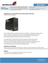
Figure 1, Figure 2 and Figure 3 show front and rear views of the platform.
Figure 1. Intel
®
Server Platform SR6850HW4, Bezel Removed

Intel® Server Platform SR6850HW4 TPS System Overview
Revision 1.0
Intel order number D23151-001
5
TP01504
2
1
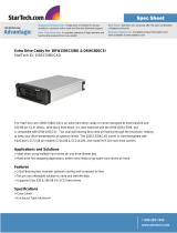
Figure 2. Server Platform SR6850HW4, Bezel and Pedestal Conversion Kit Installed
The Server Platform SR6850HW4 includes the Intel
®
Server Board Set SE8500HW4 with
the E8500 chipset. To provide structural support the Intel Server Board Set SE8500HW4
Mainboard is mounted on a sheet metal tray that is installed at the rear of the chassis,
above the power supplies.
Up to four Memory Boards can be installed into the Server Board Set SE8500HW4
Mainboard. The Memory Boards attach perpendicular to the Server Board Set SE8500HW4
Mainboard. These contain four DDR2 400HMz SDRAM DIMM slots each. With four Memory
Boards installed, the system supports up to 64GB of memory (using 4GB DIMMs).
The hard drive bay, located at the front of platform, provides a bay for ten hot-swap 1-inch
Ultra320* SCSI hard disk drives. SCSI hard disk drives plug into a vertical SCSI Backplane
Board at the rear of hard disk drive bay. One Slimline (½-inch high) optical drive bay and
one full-height 5¼-inch SCSI tape device bay are also located at the front of the platform.
The cooling subsystem requires six hot-swap system fan modules. Each fan module
contains a status LED that illuminates in the event of a fan failure. The fan modules are
accessible from the top of the system when the top cover is removed and connected into the
SCSI Backplane Board.
The front control panel provides video, USB, buttons, status LEDs, and an optional LCD,
that are used for monitoring and managing the platform. The front bezel is an optional
cosmetic accessory that is installed with snap-on features. The bezel can be customized to
meet integrator-specific industrial design requirements, including color and imprint.

System Overview Intel® Server Platform SR6850HW4 TPS
Revision 1.0
Intel order number D23151-001
6
Figure 3. Server Platform SR6850HW4, Rear View with Top Cover Removed
The power supply modules are located at the rear of the system below the Server Board Set
SE8500HW4 Mainboard and plug directly into connectors on the horizontally oriented Power
Distribution Board. The system supports two hot-swap power supply modules in a 1+1
redundant configuration or one hot-swap power supply and a power bay fan module in a
non-redundant state.
Upon removal of the top cover, the user has access to the processors, Memory Boards, PCI
adapters, IMM Board and optional mass storage features.

Intel® Server Platform SR6850HW4 TPS System Overview
Revision 1.0
Intel order number D23151-001
7
Intel
®
Server Board SE8500HW4 Main Board
FSB 0
COM1/EMP
USB Port
Video Port
External SCSI
Connector
(optional)
SCSI Channel B
Ethernet Port
Ethernet Port
Memory Board
DIMM
DIMM
DIMM
DIMM
XMB
Memory Board
DIMM
DIMM
DIMM
DIMM
XMB
Memory Board
DIMM
DIMM
DIMM
DIMM
XMB
SE8500HW4 Memory Board
DDR2 DIMM
DDR2 DIMM
DDR2 DIMM
DDR2 DIMM
XMB
FSB 1
USB Port
SIO
FWH
82801EB
ICH5
ATI*
Radeon*
7000
Video
Controller
E8500
North Bridge
(NB)
IMI A
IMI B
IMI C
IMI D
BRCM5704*
Ethernet
Controller
6700
PXH
IOP332
Processor
DDR2 RAID DIMM
RAID Smart
Battery
RAID
Act Key
SCSI Cable
Hot-swap SCSI Drives (10)
Power
Dist Board
SCSI
Backplane Board
SATA Cable
SCSI
Tape
Front Control Panel
Optional LCD
Hot Swap Fans (6)
GCM
(optional)
IMM
10/100
Front
Panel I/O
Board
Optical
Drive
SATA-to-IDE
Converter Board
Video Port
USB Port
USB Port
USB Port
Power
Power and
Signal
CPU
1
CPU
2
CPU
4
CPU
3
LSI*
53C1030
Ultra320*
SCSI
Controller
SCSI Cable
(optional)
Figure 4. Server Platform SR6850HW4 Chassis Block Diagram

System Overview Intel® Server Platform SR6850HW4 TPS
Revision 1.0
Intel order number D23151-001
8
2.3 External Chassis Features - Front
Table 2 shows the front view of the Server Platform SR6850HW4 with the bezel removed.
The front provides access to the following components:
Buttons and LEDs (with optional LCD)
Video and USB connectors
Hard drive bay, optical drive, SCSI tape device
TP01508
C
A
B
E
F
D
G
A Video connector
B USB 2.0 ports (three)
C Front control panel (button control panel shown)
D Hot-swap fans (six)
E 5 ¼ peripheral bay (full height)
F Optical drive bay
G Hot-swap SCSI hard disk drives (ten)
Table 2. Front View of the Server Platform SR6850HW4, Bezel Removed
2.3.1 Front Control Panel
The front control panel contains system control buttons and LED status indicators. It also
contains one video connector, three USB 2.0 ports, NMI button, and the system speaker.
The front bezel must be removed to access the front control panel switches and connectors.
All LEDs are visible with the front bezel installed. See Chapter 8 or a description of the Front
Panel Boards.
/