Page is loading ...

15mm Onaga Rocket Kohaya
B15-VSF-006
Please read these instructions fully before starting construction.
PVA or equivalent glue will be required to stick sections together.
Sand paper can be used to gently clean any joints.
A sharp modelling knife will be required to remove sections from the sprue. Please use knives with due care and remember
to cut away from yourself at all times.
During the construction of this model, you may find it convenient to use pegs / elastic bands to hold pieces in place while
you allow glue to dry.
Note: Due to their size / thickness certain parts on this kit are very fragile. Please use extreme care when working with
them to prevent damage.
Take the sides of the rocket motor and the two
internal bracers from the sprue.
Glue them together as shown with the etched
detail facing outwards.
The top (or bottom) panel is formed from these
pieces.
Glue the semi circles into the spaces.
Note – these are a tight fit, so it is best to do this on
a flat surface to prevent damage.
Repeat this for the other sections as shown.
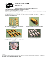
Each rocket nozzle is made from these pieces.

Glue the two “V” frames together.
Starting with the largest ring, glue them onto the
frame.
Note: The rings do not have a circular hole in the
middle – there are four flat areas which go next to
the frames.
Glue the nozzles to the back plate. They will stick
out slightly on the rear of the piece.
Glue the plates (plus the thin front plate) to the
rocket motor.
The motor “pins” are formed from the pieces
shown on the left. Put the two main pieces
together, then slide the disk over them so that its
rivets are towards the rounded end.
The ships wheel is made from these pieces.
Put the bar into the wheel, then glue the other
end to the upright.
The pieces for the front sails.
Note the shape of the “cog” supports.
The sails are FRAGILE at this stage so handle them
with care.

Turn the sail over and glue the cog pierces into
place. Attach the small square just in from the
edge of the sail. Repeat for the other front sail.
The rear sails are made from these pieces.
Note: These “cog” supports are sloped.
Add the cog supports so that the point of the
slope is away from the sail. Attach the support
pieces so they curve towards the cog supports.
We suggest you paint all the sub-assemblies for
your model at this point.
See later for painting guide.
Take the two main hull supports, the three
crossbraces and the two internal supports.
Add the internal supports to hull pieces (see pic).
There is an arrow on the support with a hole in it –
this should point towards the front of the model.
Add the three crossbraces.
Attach the piece shown above.
Slide the end of the deck under the wall piece
until the lugs on the hull supports slot into the
holes in the deck.
Add the next deck piece.

Then add the final upright and deck pieces.
The lower hull is made from these pieces.
Attach the long piece with the hole at the rear of
the model.
Glue the smaller piece into place (it only fits
properly one way round).
The stern pieces.
Slide the lower stern piece over the engine
mounts, then add the upper stern piece.
The pieces which surround the lower deck.
Starting with the two side pieces, glue them into
place, then add the two front fins followed by the
front piece.
The rear support pieces.
The flat edge goes into the hull support with the
wider end towards the front of the model.
Attach these to the hull supports.
The flat edge goes into the hull support with the
wider end towards the front of the model.
Add the rear sections.

Glue the ladders and ships wheel into place.
Place the rocket between the mounts, then slide
the pins (which are a tight fit) through the mounts
to hold it in place.
Add the front sails with the longer side
downwards.
Add the rear sails (long side downwards), carefully
inserting the lugs from the support bars into the
holes in the hull.
View of the rear sails from behind.
The completed model (Front)
The completed model (Rear)

Painting:
We constructed the model in several sub-assemblies (see instructions above).
The rocket motor and its “pins” were painted black before being dry brushed with silver.
The semi-circle pieces were painted in alternating gold and ice blue.
The metalwork on the ship was carefully painted black then once dry, silver was painted over the top.
The cloth of the sails was painted with a slightly watered down red (directly onto
the untreated MDF), allowing the paint to soak into the wood giving a very pale,
washed out look. Once dry, a second (non-watered down) coat was added on each
side of the “bones”.
The metal portions of the sails were painted in the same way as the main ships
metalwork.
The rivets on the sail mechanism were picked out with a spot of gold.
The “cogs” on the control handles were painted black / silver leaving the handle
itself as plain MDF.
The grip on each handle was picked out in white.
The flying stand was slotted together and then glued into the base.
The base was covered in PVA and chinchilla dust (or you could use a very fine sand).
Once dry it was painted a dark chocolate brown - then dry brushed with a milk chocolate colour followed by a cream
colour. All three colours were DIY household emulsion paint.
Finally spring green flock was glued into place.
/