Page is loading ...

Model Shipways Kit No. 2160
INSTRUCTION MANUAL
Manufactured by Model Shipways
A Division of Model Expo, Inc., Hollywood, FL
http://www.modelexpo-online.com
PREPARED BY BEN LANKFORD
Technical Characteristics
SCALE: 1/4" = 1' 0" (1:48)
OVERALL LENGTH: 31" (787 mm)
OVERALL HEIGHT FROM KEEL: 22" (559 mm)
OVERALL WIDTH ACROSS
LOWER YARD: 8-1/4" (210 mm)
MODELING THE
ARMED VIRGINIA SLOOP
✦
1768
✦
MODELING THE
ARMED VIRGINIA SLOOP
✦
1768
✦

HISTORY
HISTORY
The Virginia Sloop is a single-masted privateer, or smuggler, an evolutionary development in the line of fast
sailing ships linking the Bermuda sloop of c. 1740 and the trim, sharp model Virginia schooners found in
Steel’s Naval Architecture of 1805. It is a small, well-designed ship, with a graceful sheer and low freeboard.
The 18th century was a time of intense naval and maritime competition. In both peace and war, Britain, France,
and America looked toward the development of a new vessel type that might further their national or regional
interests at sea. Often, the private sector was more innovative, as the quest for quick profits spurred the produc-
tion and refinement of fast sailing ships.
Jamaica had become rapidly established as a shipbuilding center in the prior century, with a reputation for fast, well-
built ships. By the end of the century the shift to Bermuda had already begun, coincident with the decline in tim-
ber in Jamaica. When the same happened in Bermuda, the hull form seems to have moved to the Chesapeake.
Whether these ships were a new design development is not entirely clear. The basic form may have developed
from the English cutter of the first quarter of the century. However, the Jamaica-Bermuda-Virginia sloops were
sharper, lighter, and sleeker than their cutter cousins.

TABLE OF CONTENTS
TABLE OF CONTENTS
3
Technical Specifications ................................................Cover
History ...................................................................................2
Introduction and Credits .....................................................4
Before You Begin ..................................................................5
Working with the Plans & Parts..........................................5
1. The Plans ...........................................................................5
2. Making Allowances along the Way ..................................5
3. Understanding Hull Lines ................................................5
4. Kit Lumber........................................................................5
5. Britannia Metal Fittings....................................................5
6. Soldering & Working with Brass ......................................5
What You’ll Need to Start Construction ...........................6
Painting & Staining the Model ...........................................6
1. Preliminaries......................................................................6
2. Virginia Sloop’s Color Scheme ........................................7
Stage 1: Framing the Plank-on-Bulkhead Hull..................8
1. Bending Wood ..................................................................8
2. Preparing the Center Keel.................................................8
3. Installing the Stem, Keel, & Sternpost.............................8
4. Cutting the Rabbet ...........................................................8
5. Installing the Bulkheads ...................................................9
6. Installing the Wing Transom,
Filler Blocks, and Transom Frames.................................10
7. Installing the Bow Filler Blocks, Knightheads,
and Timberheads.............................................................11
8. Installing the Mast Mortise ............................................11
9. Gunport and Sweep Port Framing .................................11
10.Installing Deck Beams, Sub-Decks, and Waterway...........11
11. Main and After Rails.......................................................12
12. Before Moving On..........................................................12
Stage 2: Planking The Hull And Installing The Rails .......13
Common Shipbuilding Terms Used in the
Planking Process...................................................................13
1. Getting Started ................................................................13
2. Planking Battens & Belts.................................................13
3. Planking Butts .................................................................13
4. Spiling..............................................................................14
5. Fastening the Planks........................................................14
6. Hull Planking Scheme and Procedure............................14
7.Planking the Hull............................................................14
8. Completing the Double Planked Hull...........................17
9. Installing Bulwark Ceiling Planks...................................17
10.Installing Coamings, Deck and Cabin Planking............18
11.Installing the Main and Quarter Deck, and Cabin Rails....18
Stage 3: Completing the Basic Hull Structure ................19
Stage 4: Mounting the Hull...............................................19
1. Launching Ways ..............................................................19
2. Option – Mounting on Pedestals...................................19
3. Option – Dr. Feldman’s Stand.......................................19
Stage 5: Adding The Hull Details.....................................20
1. Anchors, Catheads, and Anchor Stowage......................20
2. Binnacle ...........................................................................21
3. Boom Crutches ...............................................................21
4. Cabin Doors....................................................................21
5. Cannon ...........................................................................21
6. Channels .........................................................................22
7. Companionway...............................................................22
8. Eyebolts, Ringbolts, and Cleats......................................22
9. Galley Stack.....................................................................22
10. Hatches, Scuttle, and Gratings .......................................23
11. Ladders ............................................................................23
12.Pumps ..............................................................................23
13. Riding Bitts......................................................................23
14.Rudder .............................................................................24
15. Steering Wheel ................................................................24
16.Stern Windows................................................................24
17. Swivel Guns and Support Posts......................................24
18. Timberheads....................................................................24
Stage 6: Mast and Spar Construction...............................25
1. Shaping & Tapering Masts & Spars ................................25
2. Building & Installing the Masts......................................25
3. Building & Installing the Bowsprit and Jibboom.............26
4. Building the Spreader Yard and Topsail Yard ................27
5. Building the Boom and Gaff..........................................27
6. Building the Flag Staff ....................................................27
7. Mast and Spar Bands, and Cleats...................................27
Stage 7: General Rigging Information .............................27
1. Rigging Scheme...............................................................28
2. Rigging Plans...................................................................28
3. Rigging Line, Blocks, Bullseyes, Hearts, & Deadeye Sizes..29
4. Block Details ...................................................................29
5. Treating the Lines............................................................29
6. Belaying Lines .................................................................29
7. Rigging Tools...................................................................29
Stage 8: Installing Standing Rigging.................................29
1. Shrouds............................................................................29
2. Spreader Yard Horse .......................................................30
3. Backstays..........................................................................30
4. Fore & Aft Stays ..............................................................31
5. Bowsprit Rigging.............................................................32
6. Footropes and Parrels......................................................32
Stage 9: Installing Running Rigging .................................33
1. Fore Staysail, Jib, and Flying Jib.....................................33
2. Mainsail...........................................................................34
3. Topsail .............................................................................35
4. Course .............................................................................38
5. Stern Flag Staff................................................................38
Final T
ouches ......................................................................38
Congratulations! ..................................................................38
Bibliography.........................................................................39

4
Instruction Manual
ARMED VIRGINIA SLOOP
✦
1768
✦
Plans and Instructions by
Ben Lankford, Vienna, VA
Models by Bob Werner
Model Shipways developed its
Virginia Sloop
kit in 1998-2000. The design is based on a reconstruction devel-
oped by Clayton A. Feldman, M.D., Publisher of Seaways’ Ships-in-Scale magazine. The original plan of the
sloop, a Dutch copy of a French drawing, was found by noted nautical historian Howard I. Chapelle in Euro-
pean archives. The ship had apparently been sold to the French shortly after completion. Fragmentary notes
and the plan passed from Chapelle to Joseph A. Goldenberg, author of Shipbuilding in Colonial America, and
to John F. Millar, author of Early American Ships. Mr. Millar redrew the plan for his book. This plan is the
basis for a reconstruction of the ship.
Dr. Feldman’s original plans are accompanied by a book,
Modeling an Armed Virginia Sloop of 1768
(see
bibliography). His book describes the development of the reconstruction and details for building a 3/8" =
1'0" scale model from scratch. Model Shipways has transformed Dr. Feldman’s design into a 1/4" = 1'0" scale
kit design. Some modifications have been made in keeping with Model Shipways design procedures, and
some minor changes in the rig have been made based on further research. Model Shipways would like to
thank Dr. Feldman for making this design available and for his assistance during the kit’s development.
Thanks also to Jack Silvia, Little Compton, RI, for his assistance in assembling prototype hulls and checking
the accuracy of the laser-cut parts, and reviewing plans and instructions, and to Bob Werner, Hollywood, FL,
for assembling the prototype model, photos of which are included herein.
Copyright 2001
Model Shipways, Inc., a division of Model Expo, Inc.
Hollywood, Florida

5
Before You Begin
The
Virginia Sloop
is an interesting ship
and makes a splendid model. The model
is well suited for the beginning ship mod-
eler. At 1/4" = 1'0" scale, it is easy to
build and obtain precise detail. Plank-on-
bulkhead hull construction with laser-cut
parts offers a unique building method
that assures an accurate hull form. The
model has double outer hull planking
(with single planking option suggested),
and all exposed surfaces except for decks
and spars are walnut, for those who desire
a natural oiled finish. Color schemes are
provided for those who prefer to paint
the model.
The plans and instructions included have
been expanded from previous Model
Shipways kits in an effort to assist the
beginner.
Britannia, brass, and wooden fittings
eliminate creating many parts from
scratch. However, some require final fin-
ishing before they are suitable for the
model. This is especially true for the bri-
tannia fittings and will be discussed later.
Always complete one construction stage
before moving to the next. When things
go awry, consider doing them over.
Working with the Plans & Parts
Before starting the model, carefully exam-
ine the kit and study the plans. First,
determine if all the listed parts are pres-
ent. Handling them will produce a better
understanding of the kit’s requirements.
Try to visualize how every piece will look
on the completed model. Also, determine
the building sequence – what must be
done first – ahead of time. The instruc-
tions will help, but a thorough knowledge
of the plans at the outset is essential.
T
o avoid losing small fittings and hard-
ware, sort them into labeled boxes or com-
partments. These should have lids to keep
out dirt.
1. The Plans
Seven plan sheets are provided:
1. Laser-Cut Wood Patterns
2. Hull Framing and Planking
3. Deck Plan, Profiles, and Deck
Structures
4. Mast & Spar Details, Sail Plan,
& Belaying Plan
5. Standing Rigging
6. Running Rigging (1 of 2 Plans)
7
.Running Rigging (2 of 2 Plans)
Model Shipways’
Virginia Sloop
kit is
manufactured to a scale of 1/4" = 1'0"
(1:48). Each sheet is drawn to that scale
except areas enlarged to show detail. Most
dimensions can be lifted directly off the
plans by using draftsman dividers or a
“tick” strip (piece of paper such as an
adding machine roll). Lay the paper strip
over the plan, carefully mark the item’s
length with a sharp pencil, then transfer
the marks to the wood.
Because these are modelbuilding plans,
actual measurements are given in model
inches. For comparison, 1/32" on the
model is equal to 1.5" on the real ship,
1/16" is 3", 1/8" is 6", and so on. The
table on Plan Sheet 3 compares scale with
full-size dimensions and converts imperial
numbers to metric.
2. Making Allowances
along the Way
Try to be exact when following the plans,
but use common sense. Adjustments may
be necessary to compensate for small dif-
ferences in how your model is shaping
up; i.e., perhaps the mast has too much
rake (the angle at which it sits). Lines
should not drape over fittings or conflict
with other lines when
belayed
(secured). If
necessary, move a belaying point. Put
yourself on the ship, imagine performing
the task, and use logic.
3. Understanding Hull Lines
Beginners may not be familiar with the
following hull lines.
Buttock lines
are verti-
cal longitudinal planes cutting through
the hull.
Waterlines
are horizontal planes,
and Sections are transverse vertical planes.
Diagonals
are planes cut almost perpendi-
cular to the station lines. These lines define
the hull’s shape and are used by the drafts-
man to fair it (create even curves).
A complete set of hull lines is not needed
for this model, because laser-cut bulkheads
and the center keel define the hull’s shape.
Plan Sheet 2 shows the bulkhead lines.
They are similar to a ship’s
body plan
, or
sections, and illustrate how the hull curves
from top to bottom.
4. Kit Lumber
Strips and sheets of basswood and walnut
are supplied in the kit. Model Shipways
occasionally substitutes lime (
Tilia vul-
garis
), a European wood, for basswood
(
Tilia americana
) in its kits. Both have a
fine, uniform texture and straight grain.
Lime, however, has superior steam-bend-
ing qualities. It is often called basswood
in Europe.
Some of the walnut supplied in the kit will
be purchased from a foreign source in met-
ric units. Consequently, there may be a
slight variance from the walnut dimen-
sions shown on the plans and in the
instructions. However, this should present
no significant problems.
Sorting the wood in the kit by thickness
and wood type will save time. After
selecting and cutting what you need,
return the remaining stock to the proper
thickness and wood-type pile. Don’t
worry about using a piece for one item
intended for another. Model Shipways
supplies enough extra wood to complete
the model before running out.
5. Britannia Metal Fittings
These fittings will require final finishing
before mounting on the model. First,
remove mold joint flash with a #11 hobby
blade, then file or sand with fine sandpaper.
Next, wash fittings in dishwashing liquid
and warm water to remove traces of mold
release agent and the body oils your fingers
deposit. Allow to dry thoroughly before
applying primer and painting.
6. Soldering & Working
with Brass
Extensive soldering isn’t required to assem-
ble the
Virginia Sloop
. However, here are a
few tips:
Cut brass sheets and strips with a small
pair of tin snips or heavy scissors. Thicker
brass will require a jeweler’s saw. After cut-
ting, smooth the edges with needle files
followed by wet-or-dry fine sandpaper used
dry. Cutting slivers from brass sheet curls
and bends it sideways. To straighten, grip
the ends with a pair of small pliers and
pull in opposite directions. Thin brass
sheets can be scored with a utility knife
and metal straight edge, then snapped off.
Use two or three light passes, cutting
against a maple chopping block, birch
board, or glass.
Drilling holes in brass with a pin vise is a
slow process. The solution is to mount a
handpiece for flex-shaft machines in a
hobby drill press. Several companies manu-
facture this tool, and it is worth the cost.
When working with brass, use a 1/4" or
thicker piece of maple or birch for backing.
(Avoid softwoods, as these flare the exit
hole.) To prevent the bit from wandering,
mark the spot with a small center punch.
Lubricate the bit with light oil and drill
slowly to avoid breakage. The brass will
become hot, so clamp the pieces to the drill
press table or hold them down with a
wooden stick. Do not touch the brass! If
possible, keep the RPM below 2000. Any-
thing higher will generate enough heat to
break small drill bits.
In the past, many modelers used pure sil-
ver solder to avoid the corrosive qualities
of lead in soft solder. T
oday, many solders
are lead free. They are composed of tin
and antimony, or tin and a small amount
of silver (3 to 4 %). These solders are strong
and melt at approximately 430˚ F. Conse-
quently, no reason exists to use pure silver
solder (melts at 1300˚ F).
The key to soldering is keeping the brass
clean. Use a solvent made especially for
cleaning metal parts or a simple substitute
such as vinegar, lightly sand, or do both.

6
Rinse parts in clean water after cleaning
them with a solvent. Once the parts are
cleaned, don’t touch them — your fingers
will leave greasy spots. Soldering is easy if
your work is set up properly. First, immo-
bilize the parts in a fixture or other hold-
ing device, then add just enough rosin or
acid paste flux to the joint to do the job.
Solder flows where flux is applied. Next,
heat the joint with a small torch or pencil
soldering iron. This sequence is important.
The larger the parts, the longer it takes to
heat the brass and melt the solder. Remove
excess solder with needle files. Better yet,
use a desoldering syphon or braid to
remove globs of solder before it hardens.
The joint should look like the real thing,
not a big glob of fillets.
What You’ll Need to Start Construction
The following items are recommended for
building the model. Those who have
modeled before may have their favorites.
A. Knives and saws
1. Hobby knife with #11 blades
2. Razor saw or jeweler’s saw
B. Files
Set of needle files; steel or diamond
coated
C. Clamps
1. A few small C-clamps
2. Wooden spring-type clothespins
(craft shops have small versions)
3. #16 and #33 rubber bands
D. Tool Set
Small carving tool set or individual
gouges and chisels for carving keel rab-
bets, stern wing transom, and filler
blocks, and tapering the stem and rudder.
E. Sharpening Stone
Keeps tools razor sharp.
F. Boring Tools
1. Miniature bits sizes #60 to #80
2. 1/16", 3/32", and 1/8" bits
3. Pin vise
G. Miscellaneous
1. Tack hammer
2. Tweezers (a few)
3. Small, fine pointed scissors
4. Miniature pliers
a. small round
b. flat nose
5. Small bench vise
6. Soldering iron or torch
a. solder
b. flux
7. Beeswax block (for treating
rigging lines)
8. Masking tape
9. Wire cutters (for cutting
fine wire and strip metal)
H. Sandpaper
1. Fine and medium grit garnet or
#100 to #220 aluminum oxide
2. #400 wet-or-dry sandpaper
I. Sail cloth
Light weave cotton or linen cloth if
sails are desired. Model Expo sells a
suitable cotton cloth.
J. Finishing
1. Paintbrushes
a. Fine point for details
b. 1/4" to 1/2" flat square for hull
K. Supplies:
1. Paints
2. Primer
3. Stains and varnish
4. White or woodworker’s
(yellow) glue
5. Cyanoacrylates
(generic name is Super Glue)
6. Five-minute epoxy
7. Wood filler
Note:
White or woodworker’s glue in yel-
low or tan will suffice for most of the
model. Five-minute epoxy provides extra
strength for affixing fittings. Cyanoacry-
lates, such as Jet, Flash, or Zap, produce
quick adhesion. For most applications,
the medium viscosity, gap-filling variety is
best. The thin type is recommended for
filling a narrow crack or tacking hull
planking to the bulkheads.
Painting & Staining the Model
Beginning this manual with directions on
applying finishes may seem strange. Not
so! Much time and effort can be saved
and more professional results obtained if
the finishing process is carried on
throughout construction. Proper timing
in applying finishes and using masking
tape to define painted edges should elimi-
nate unsightly glue marks and splotchy,
stained surfaces. Take advantage of these
general suggestions:
1. Preliminaries
Sanding and cleaning:
Rub down external
surfaces with 220 grit sandpaper, then wipe
off every speck of dust. Give surfaces to be
painted two light coats of primer. Sand
lightly after the last application. Don’t
sand down to bare wood. After washing
your hands, gently dust the hull with a soft
brush and clean, soft cloth or tack rag. Use
a spackling compound, such as Model
Magic or DAP, to fill any scratches and
defects, then sand and prime again.
Preparing walnut for painting:
This kit
contains walnut wood for most of the
outer surfaces. Walnut is an excellent wood
for a natural oil or varnish finish. However,
if you intend to paint any walnut, the use
of a paste filler or spackle is highly recom-
mended. Walnut has a more pronounced
grain than a wood such as basswood or
cherry. Filling the grain will result in a
more satisfactory painted surface.
Choosing paint:
Glossy surfaces are not
desirable on ship models. A flat finish or
one with a slight sheen is best, because it
doesn’t reflect daylight or artificial lights.
Consequently, details show up better. How-
ever, the undercoat or primer should be
dead flat. A primer gives the surface a little
tooth and helps top coats adhere better.
Many hobby paints are satisfactory,
including Model Shipways, Testors,
Humbrol, and Tamiya. Jo Sonja artists’
paints (used by bird carvers) are also
acceptable. They are a combination
acrylic-gouache and dry dead flat.
Hobby paints have a variety of reflectance
levels from flat to gloss. When using a
mixed group of reflectance levels, finish
the completed model with a flat, clear
coat. It will provide durability and seal
any decals or dry-transfer lettering.
Brush painting:
Painting with fine, soft
bristle brushes is probably best for the
beginner. Many skilled modelmakers pre-
fer the brushed-on technique, because its
subtle imperfections impart a more life-
like appearance to the model. Brushes
must be soft and of the highest quality.
Artist-grade sable or synthetics are the
best. Use wider brushes for painting
broad surfaces. If too narrow, the bristles
will cause excessive streaking.
When applying paint or stain with a
brush, lay down one thin coat in a single
stroke, then move to an adjacent area and
coat it with a single stroke. Never go back
over fresh paint. That will tear up the sur-
face. Wait until it has dried to a hard fin-
ish before applying a second coat.
Spray painting:
Although slightly expen-
sive, a Paasche, Badger, Testors, Revell-
Monogram, or similar airbrush will
produce a first-rate job and is worth the
investment. Airbrushes are either single-
action (trigger controls only airflow) or
double-action (trigger controls air and
paint), and they are easy to use. Spray
patterns can vary from thin to about 1/2"
wide by either adjusting the needle or
installing a different, sealed nozzle. In
some brands, paint travels through the
airbrush body to the needle. These
require disassembling to clean. Other
designs bypass the body and bring paint
directly to the nozzle. These clean by sim-
ply spraying solvent through them.
Paints are either water- (acrylic) or solvent-
based. Solvent-based paints spray best.
Acrylics are difficult to spray and must
definitely be used with the manufacturer’s
recommended thinner or with alcohol,
a satisfactory substitute. Thinning
water-based paints with water creates sur-
face tension problems, resulting in poor
coverage and spray atomization. Experi-
ment when using acrylics. Some modelers
have success and others don’t.

7
When using solvent-based paints, work
outdoors or equip your shop with a spray
booth. These fumes are toxic.
Many brands of aerosol paint produce
good results. However, test them on scrap
wood before spraying the model. Aerosols
put out a lot more paint than an airbrush,
so be careful to avoid runs. Spray on sev-
eral light coats.
Most paint manufacturers have special
thinners for their various paint lines. Fol-
low each manufacturer’s recommenda-
tions. Mixing brands is not a good idea,
because they may not be compatible.
Sometimes, however, no other option
exists. If so, apply each brand separately
and allow to dry thoroughly before
adding the next. Always test to make sure
the final flat or gloss finish is compatible
with the paint it will cover.
Masking surfaces:
Masking can be a
tricky process. Some brands of masking
tape are worthless, because they allow
paint to seep underneath their edges. For
masking fine stripes or straight and
curved lines, use a graphic arts tape such
as Chart Pak. It comes in widths as fine as
1/64". Chart Pak tapes have superb adhe-
sion and won’t bleed when firmly applied
(burnishing is recommended). Black plas-
tic electrician’s tape and Scotch Remov-
able Magic Tape are also excellent.
Scotch’s tape has the same, low stick
adhesive as its famous Post-It pads. In
fact, Post-It tape flags can be used for
masking.
2. Virginia Sloop’s Color Scheme
Three color schemes are suggested as follows:
Painted model
This scheme would be typical for an origi-
nal ship of this period.
Note:
Refer to the instructions in the pre-
vious section regarding painting of walnut
before you proceed.
Main rail, quarter deck and cabin rail,
taffrail, and fashion pieces — Black
Black strake and wales — Black
Molding on black strake (top edge of
black strake) — Antique gold
Hull side and transom planking down to
the black strake — Yellow ochre
Option: Paint the sheer strake under the
main rail light blue, red, or green.
Swivel gun posts — Yellow ochre
Hull below the wales — Tallow
Stern window frames — Antique gold
Timberheads — Natural finish
Inside bulwarks — Dull red
Inside of gunports — Dull red
Decks, including waterway, and cabin
top — Natural finish
Cabin front and doors — Natural finish
Companionway — Natural finish
Binnacle — Natural finish
Bitts — Natural finish
Steering wheel — Paint casting color of
natural wood
Steering wheel stand and drum — Natural
finish
Hatch coamings — Natural finish
Hatch covers — Natural finish
Grating — Natural finish
Galley stack — Black
Quarter deck ladders — Natural finish
Catheads — Dull red inboard (same as
bulwarks), black from inboard edge of rail
and outboard
Iron work (pintles and gudgeons, chain
plates, hatch rings and cannon carriage
rings, mast cap, bowsprit straps, compan-
ionway hinges, cabin door hinges, and
jibboom irons) — Black
Anchors — Black shank with natural finish
stock
Cannon barrels and swivel guns — Black
Cannon carriages — Dull Red
Cannon trucks — Black
Boom crutches — Natural finish
Mast — Natural finish with black mast
wedge/coat. Black masthead and very top
of topmast.
Boom and gaff — Natural finish. Black at
very end of boom and gaff.
Yards — Natural finish. Black yardarms.
Bowsprit — Natural finish
Jibboom — Natural finish. Black at very
end of jibboom.
Blocks — Natural finish
Note: For the above colors, the following
Model Shipways acrylic marine paints
approximate the colors:
Black — Hull/Spar Black, MS4830
Y
ellow Ochre — Hull Yellow Ochre,
MS4829
Tallow — Hull Tallow, MS4803
Dull Red — Bulwarks/Gun Carriage Red,
MS4802
Antique Gold — Antique Gold Trim,
MS4806
Note: For natural finished basswood decks
and beech dowel spars, we suggest using
a light tan or maple stain, followed by oil
or low gloss polyurethane varnish. For
natural finished walnut items, use a clear
oil finish.
Natural finish
Many natural finished models are dis-
played in European museums. Conse-
quently, the process is most popular
overseas. It has also become popular as a
result of foreign kit sales in the US. Most
foreign kit models feature walnut plank-
ing. This scheme retains the natural beau-
ty of walnut.
For all walnut areas, use an oil finish such
as tung oil or Danish oil. No stain is
required. For best results apply about three
coats of oil, buffing between coats. The
more oil you add the higher the sheen. For
the basswood decks and birch dowel masts,
stain the wood first. A light maple or pine
stain would be most appropriate.
As an option, use a polyurethane satin
varnish in lieu of oil.
Natural finish with touches of color
A pleasing balance between a natural and
fully painted model.
Use an all-natural finish, except for touch-
es of color. You could use the colors listed
above for rails, bulwarks, catheads, black
strake and wales, black strake molding,
sheer strake, galley stack, and all iron-
work, stern windows, cannon barrels,
swivel guns, and anchors. Or, make a
choice of your own.

Stage 1:
Framing the Plank-on-Bulkhead Hull
Before getting started on this project,
a few important terms and abbreviations
are in order, especially if you are a
beginner.
Port or (P) — Looking forward, this is the
left side of the ship.
Starboard or (S) — Looking forward, this is
the right side of the ship.
P/S — A designation you will see on plans
and in instructions. This tells you that the
same identical part, rig, or whatever,
appears on both the port and starboard
sides of the ship in the same location.
Model Shipways plans are drawn showing
the starboard side of the ship. In this case,
the bow is pointing to the right. This is
common practice for model plans as well
as real ship plans.
Some of the other stages will have specific
terms defined to help you understand terms
used on the plans and in the instructions.
1. Bending Wood
Building a plank-on-bulkhead hull
requires bending some wood without
distorting its desired position (doing so
stresses glue joints and fasteners). Wood
can be bent by:
Steam bending:
Hold the plank over a
kettle of boiling water and bend. Hold
the wood in position until it cools.
Although the plank should remain in that
shape, it may spring back slightly.
Microwave steaming:
Wrap the planks in
a wet paper towel before heating. Since
microwaves differ in wattage, experiment
to determine what power level to use and
for how long.
Soaking:
Submerge the plank in warm
water for several hours. Try adding a little
household or pure ammonia. This speeds
up the process, making the fibers slippery
so the wood bends more easily. After
soaking, place the plank in a fixture until
completely dry.
Soldering iron:
Large soldering irons with
a tubular end are ideal. Clamp the iron
upright in a vise. While the iron heats,
soak the strip of wood in tap water. Some
modelers prefer bending around the tube
near the handle (it’s not as hot), while
others use the shank. Move the strip back
and forth against the iron. Its heat turns
water into steam and drives it into the
wood. The trick is to wait until you feel
the wood wanting to yield before starting
the bend. Begin too soon or apply too
much pressure and the strip will break.
The wood dries rapidly, so care must be
taken to avoid scorching. Resoak and
reapply it to the iron until the desired
shape is achieved. Once the piece is
formed, it can go directly on the model.
Because the wood’s memory has been
permanently altered, it will never spring
back to its former shape, meaning no
stress on any timber or fasteners. Spend
some time acquainting yourself with this
method, and you’ll never bother with fix-
tures again.
Another soldering iron approach is to
turn a tip from hard aluminum, then file
a 45˚ angle on one end. Insert the tip in a
20- or 30-watt soldering iron and heat it.
Soak the wood for five minutes, then let
it dry for five minutes. (Woods take on
water faster than they can release it.) Hold
the tip against the wood to heat it. When
supple, bend the plank over a form, or
simply lift the end as heat is applied and
bend by hand.
Commercial plank benders:
Model Expo
sells an electric plank bender designed for
controlled heat. Another tool (Amati’s
Form-A-Strip, available from Model
Expo) bends planks without soaking or
heating. It looks like a pair of pliers with
one flat jaw and a chisel for the other.
When squeezed on a plank, the chisel
depresses one side of the wood, causing it
to bend. Repeat the process along the
plank until it assumes the correct curve.
However, squeezing too hard will cut the
wood in half. This tool bends planks in
only one direction, so it’s good for bow
planks, but not those at the stern.
2. Preparing the Center Keel
The center keel is laser-cut from basswood.
With a sharp pencil, draw lines below the
bulkhead slots from the slot down to the
bearding line to help align the bulkheads
when slid into the slots. Then draw the
bearding line shown on the pattern on
Plan Sheet 1. Mark on both sides of the
center keel. Be critical and measure from
several points on the plans when marking
the lines.
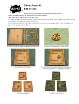
3. Installing the Stem, Keel,
& Sternpost
The stem, keel, and sternpost are laser-cut
from walnut. Add them to the center
keel. Taper the stem as shown on the
plans. Align and hold the pieces with
dowels, located as shown on Plan Sheet 2
or wherever suits you (
Figure 1-1
).
Note:
The Figure suggests tapering the
parts before installing. However, you may
find it easier to do this later. If something
is not exactly square, tapering later will
give you a chance to make the tapers
more even on each side.
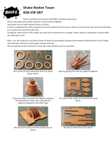
4. Cutting the Rabbet
The
rabbet
is a generic term referring to
the entire groove where planks are fitted
along the stem, keel, and sternpost. The
rabbet line is the glue line between the
stem, keel, and sternpost and the center
keel. The
bearding line
is the intersection
of the center keel with the planking’s
inner face. Measure the bearding line’s
location from Plan Sheet 1 (you already
should have done this), then mark it on
both sides of the center keel.
Note:
The rabbet varies depending upon
its location. Cut the depth of the rabbet
to suit the thickness of combined outer
and inner layer of planking. Do this with
a #11 hobby blade. Using a 1/8" or 1/4"
wide flat chisel, start the rabbet cut at
the bearding line and cut a tapered
groove toward the rabbet line. The plans
show a sketch of the actual shape of the
rabbet cut.
To judge the rabbet angle, position a
scrap plank against the keel as you carve.
The double planking scheme consists of a
basic 3/64" thick first layer of basswood
covered by 0.020" walnut strips. Glue a
short piece of these strips together for
your scrap test plank. When the hull is
8
FIG. 1-1 INSTALLING KEEL, STEM & STERNPOST
STERNPOST
STEM
USE 1/16" DOWEL FOR ALIGNMENT
KEEL
GLUE
CENTER
KEEL
TAPER BEFORE
INSTALLING GLUE
PRE-FIT PARTS
GLUE

9
planked, these timbers should lie flush
on the cut portion from bearding line to
rabbet. When cutting the rabbet amid-
ships and forward, temporarily insert the
bulkheads in the center keel slots to
determine the angle the planks will take
when installed. Use your scrap plank at
these angles when cutting the rabbet. The
rabbet detail is shown on Plan Sheet 2
and in
Figure 1-2
.
When cutting the rabbet at the stern, work
slowly. The port and starboard rabbet cut
nearly meets at the center of the center keel.
Work too fast and you might cut through
the entire center keel.
5. Installing the Bulkheads
The bulkheads are laser-cut basswood.
Label the bulkheads A through R. Test
each one to make sure it slides into the
correct center keel slot. If the fit is too
tight, sand the slot. Bulkheads should fit
snugly with a little tolerance for glue.
Use a tick strip to transfer the bevels
shown on Plan Sheet 1 to the bulkheads.
Mark them in pencil. Cut the bevels with
a #11 hobby blade per
Figure 1-3
. Deck
bevels and side bevels amidships are
hardly measurable. These can be sanded
in after the bulkheads are installed.
The bevels are required on both the inner
and outer sides of the bulwark stanchion
extensions (
timberheads
). The extensions
on the forward bulkheads are rather thin,
so be careful not to break them off as you
work. Once the hull is planked with out-
board planking and inboard ceiling
plank, the bulwarks will have sufficient
strength. As an option, you can cut the
outside bevel for outer hull planking and
wait until the hull in planked before
beveling the inside. This would maintain
a stronger bulwark as you work on the
outer planking.
Glue the bulkheads in place. Make sure
the top of each bulkhead is flush with the
top of the center keel. Use a small
machinist square to set each bulkhead
perpendicular to the center keel, then
tack a temporary strip to the top of the
bulkhead to hold it in place while the
glue dries (
Figure 1-4
).
After installing all the bulkheads, check
the straightness of the center keel with
a straight edge, then tack or tape a temp-
orary batten (just a strip of wood) on
each side of the hull on the outboard
edge of the deck (
Figure 1-5
). This is a
critical step. Measure the spacing
between each bulkhead on both sides
and retack the battens until the hull is
aligned. These battens should remain in
place until you do some planking, or
better yet, add a permanent strut between
each bulkhead for added rigidity, then
remove the battens.
FIG. 1-2 CUTTING THE RABBET
INSTALL BULKHEAD TEMPORARILY
TO DETERMINE PLANK ANGLE
CHISEL
BEARDING LINE –
DON’T CUT ABOVE IT
RABBET
CUT DEPTH
WITH HOBBY KNIFE
FIT SCRAP
PLANK TO
CHECK FIT
STERN
AMIDSHIPS
FIG. 1-3 BEVELING THE BULKHEAD
SLIGHT BEVELS CAN BE
SANDED LATER
PENCIL MARKED
BEVEL
CAREFUL!
DON’T CUT INTO
MAXIMUM WIDTH
EDGE
HOBBY
KNIFE
CUT BEVEL ON
BOTH SIDES OF
BULWARK
STANCHION
EXTENSIONS
FIG. 1-4 INSTALLING BULKHEADS
FLUSH HERE
SAND BEVEL LATER
WHERE DECK HAS SHEER
GLUE
CHECK 90° ANGLE
WITH SQUARE
LINE UP ON
PENCIL MARKS
TACK
TEMPORARY
STRIP WHILE
GLUE DRIES
CAREFUL!
WATCH
WHICH SIDE
BEVEL IS ON
FIG. 1-5 ALIGNING THE HULL
TACK
TEMPORARY
BATTENS
ADD OPTIONAL PERMANENT STRUT
BETWEEN EACH BULKHEAD FOR
ADDED RIGIDITY – BOTH SIDES
CHECK SPACING BETWEEN
BULKHEADS
CHECK
STRAIGHTNESS
OF CENTER KEEL
WITH STRAIGHT
EDGE

SAME THIS SIDE
WING TRANSOM
FILLER BLOCK
FIT ROUGH SHAPED BLOCK
FINISH CARVING ON MODEL
RABBET
BEARDING LINE
BULKHEAD
“R”
BEVELED
FIG. 1-9 FRAMING THE STERN
SLOPE AND
BEVEL PER PLANS
STERN FRAMES
BULKHEAD “R”
WING TRANSOM
END BLOCK
CARVE ON MODEL
WINDOW
HEADER
AND SILL
CENTER
KEEL
10
Be certain the bottom of each bulkhead
feathers out at the bearding line. Trim as
necessary to line up. Bottoms on the
most narrow bulkheads may be slightly
above the bearding line caused by laser
burning the narrow wood (
Figure 1-6
).
Next, sand in the bevels that were not
precut. Lay a 1/8" thick square basswood
batten against the bulkhead edges at vari-
ous locations to check the hull’s fairness
(
Figure 1-7
). Sand or add shims to correct
bumps and dips. This is an important
check; hull planks must lie flat against the
bulkheads. Due to the
Virginia Sloop’s
numerous bulkheads, manufacturing or
assembly errors can occur. Beginners tend
to rush this step and jump right into
planking. Take your time and check the
fairness thoroughly. Then, you won’t run
into problems when you start planking.
6. Installing the Wing Transom,
Filler Blocks, and Transom
Frames
Carve the wing transom (two halves) from
a basswood block included in the kit. Use
the shape shown on Plan Sheet 2, and
glue the wing transom halves to the aft
side of Bulkhead R and to the center keel.
Below the wing transom, fit and carve the
basswood filler pieces. This is nothing
more than a filler between the edge of
Bulkhead R and the wing transom so the
hull planks have some gluing surface. On
a real ship, this area would also be filled
with stern framing (
Figure 1-8
).
On top of the wing transom and against
Bulkhead R, glue the six laser-cut bass-
wood stern frames. You will need to taper
the top and bottom first, as they sit at an
angle. Also, the center frames (one on
each side of the center keel) must be
tapered from bottom to top, or just taper
an area in way of the windows. Angle the
frames so they are in line with the sides of
the stern windows. Double check the
location of these frames, because the stern
window frames (these windows are also
called stern lights) will fit between them.
Fit a header and sill piece for each win-
dow. These can be basswood, since they
do not show after the window frames are
added. The header piece also serves to
provide end support for the cabin top
sub-deck and planking. Finally, fit and
carve the filler blocks on each side out-
board of the outer stern frame. These butt
into Bulkhead R and are carved to the
hull form.
Figure 1-9
illustrates the stern framing.
This is a good time to paint the interior
black so that nothing will show through
the windows after the planking has been
installed.
FIG. 1-6 BULKHEADS AT BEARDING LINE
TRIM IF
LONG
SHIM IF
SHORT
SMOOTH FLOW
INTO RABBET
CENTER
KEEL
BEARDING
LINE
BULKHEAD
FIG. 1-7 FAIRING THE BULKHEADS
BATTEN
SINCE GAP IS SHOWING UP AT E, G & H,
MOST LIKELY F IS THE PROBLEM
BULKHEAD. TRIM F AND RECHECK.
GAP – NEED TO ADD SHIM TO EDGE OF
BULKHEAD
SEVERAL ADJACENT BULKHEADS OK
FIG. 1-8 STERN WING TRANSOM & FILLER BLOCKS

11
7. Installing the Bow Filler Blocks,
Knightheads, and Timberheads
Forward of Bulkhead A, install the filler
blocks on both sides. Carve from bass-
wood blocks included in the kit. The plan
provides some sections through the block.
To aid you with carving the blocks correct-
ly, make templates from these sections. Fit
the templates as you carve the blocks —
you could easily flatten the block and not
have the fair waterline curves in way of the
block. These blocks provide a gluing sur-
face for the forward end of the hull planks.
It is suggested that you pre-carve the blocks
close to the waterlines before placing on
the model, then finish the correct shape
while on the model, using battens to make
sure the blocks flow along hull lines. Fit
the knightheads and timberheads in notch-
es cut in the filler blocks. The plan shows
the shape of theses parts (
Figure 1-10
).
8. Installing the Mast Mortise
Since Bulkhead F interferes with the mast
going into the hull very far, the heel of
the mast must be tapered and fit into a
socket (mortise box) on the center keel.
Figure 1-11
and Detail 2-C on Plan Sheet
2 illustrates the socket. Do the socket
now, because you cannot get to it after
the deck is planked. Cut the tenon in the
bottom of the mast so it fits the socket.
9. Gunport and Sweep Port Framing
The bulkheads are located to form the
sides of all the gunports but allow space
for lining the sides of the openings with
0.020"-thick walnut strips. The walnut
strips are not a required construction fea-
ture, but are added only to retain a walnut
covering for those who desire a natural
finish. Stage 2 discusses this further.
Fit a basswood header and sill between
the bulkheads. Add these pieces to project
slightly beyond the bulkhead extensions,
then sand flush inboard and outboard
(
Figure 1-12
).
The sweep ports are shaped like an oar
blade with a hole in the center for the han-
dle. Since these openings will be cut
through the bulwark, you need a filler piece
in between. Add a filler piece just wide
enough to cover the opening (
Figure 1-13
).
Like the gunport headers and sills, sand
flush with the bulkhead extensions. The
actual opening for the sweep ports can wait
until the exterior hull and ceiling plank are
installed; then, cut the openings through
the entire side. However, it would be a
good idea to drill the center hole for the
ports through the filler piece at this time.
10. Installing Deck Beams,
Sub-Decks, and Waterway
Deck beams:
Before you can install the
sub-decks and plank the deck you’ll need
some deck beams — one to support the ends
FIG. 1-10 FRAMING THE BOW
FILLER FOR
HAWSE HOLE
NOTCH FOR
TIMBER HEAD
NOTCH FOR
KNIGHT HEAD
BULKHEAD “A”
SAME BOTH
SIDES
RABBET
FILLER
BLOCK CARVE TO WATERLINES SHOWN
ON PLAN SHEET 2
MAKE TEMPLATE FOR EACH WATERLINE
TO AID CARVING
FIG. 1-11 MAST MORTISE
BULKHEAD “F”
GLUE SECURELY
CENTER
KEEL
1/8" OR ANY GREATER
THICKNESS
FIG. 1-12 FRAMING GUNPORTS
HEADER
SILL
SAND FLUSH
INBOARD AND
OUTBOARD
FIG. 1-13 SWEEP PORT FILLER BLOCK
SAND FLUSH
INBOARD AND OUTBOARD
SHAPE OF SWEEP PORT
CUT NOW OR AFTER
PLANKING

FIG. 1-15 INSTALLING SUB DECKS
TRIM SUB DECK IF NECESSARY
TO FIT. TIGHT FIT NOT REQUIRED.
WATERWAY WILL COVER
TACK AND GLUE TO BULKHEADS
SUB
DECK
FIG. 1-16 INSTALLING THE WATERWAY
CEILING
WATERWAY
DECK PLANK
SUB DECK
12
of the main deck planking at the quarter-
deck, and two to support the forward and
aft ends of the quarterdeck planking. All
three beams fit in precut notches in the cen-
ter keel. These beams are laser-cut basswood
but will need trimming on the ends to fit.
The two forward beams are butted against a
strip fitted between bulkheads (
Figure 1-14
).
Sub-decks:
The kit is supplied with laser-
cut 1/32" thick basswood sheet as a sub-
deck under the basswood deck planks and
walnut cabin top planking. This provides
a firm support for the hatch coamings
and deck planks. Also, many modelers
like to mark the planking runs in pencil
on the sub-deck as a guide before actually
installing the planks. The sub-decks
include cut-outs for the bulkhead timber-
head extensions and the locations of
hatches, pumps, bitts, and the mast mor-
tise. The laser-cut sub-deck may need to
be trimmed a bit to fit against the bulk-
head timberheads (
Figure 1-15
).
Note:
The decks have both camber and
sheer. This means the sub-deck sheet must
be bent in two directions to fit the top of
the bulkheads. Before gluing, pin the deck
bulkhead by bulkhead pinning at the center-
line, then along the side. This sort of relieves
the stress in the deck so it will fit. Just make
sure the sub-deck will lie flat on all bulk-
heads and the center keel before gluing.
The sub-decks can be glued to the bulk-
heads from below, but you will need to
use a brush or stick to reach the deck
between the narrowly spaced bulkheads.
A better way is to pre-drill small holes
through the sub-decks in way of the bulk-
heads. With the sub-decks pinned securely
to the bulkheads, squirt some super glue
through the holes. Capillary action will
distribute the glue along the bulkhead.
W
aterway:
The laser-cut walnut waterway
runs from the quarter deck to the bow
inside the bulwark extensions. The laser-
cut is a rectangle in cross section. Shape
it as shown on Plan Sheet 2, Section A-A
and in
Figure 1-16
. Glue the waterway on
top of the sub-decking and against the
bulwark stanchion extensions.
11. Main and After Rails
These will be installed after the hull and
bulwark planking is completed. Refer to
Stage 2.
12. Before Moving On
Before proceeding with the hull and ceiling
planking, check all the framing. Make sure
it is all in place and all nice and flush. The
framing sets the foundation for the final
planking — you don’t want to get started
and find out that something is out of skew.
Double check those bulkhead bevels, so
you know when you plank you will have a
fair hull form. Many beginners tend to rush
through this stage only to find they are
really not ready for attacking the planking.
FIG. 1-14 DECK BEAMS AT QUARTER DECK
CENTER KEEL
BULKHEAD “O”
QUARTER
DECK
BEAM –
GLUE TO
BULKHEAD
“O”
BEAM END
SUPPORTS BETWEEN
BULKHEADS “M” AND “N”
QUARTER DECK
BEAM
MAIN DECK
BEAM
N
M

13
Stage 2:
Planking The Hull And Installing The Rails
1. Getting Started
Most modelers find planking tedious.
Work slowly and think of each plank as a
project unto itself. Since hull sides are
identical, simultaneously cut one pair of
port and starboard planks to shape. Fit
the plank on one side, then the other.
Don’t rush. Speed results in frustration
and a poor job.
Before starting, secure the hull upside
down in a vise or cradle. Something
portable that rotates is ideal. Model Expo
sells a planking vise for this purpose.
2. Planking Battens & Belts
Hulls are easier to plank when divided
into belts. They flow along the hull in
smooth curves. Each is designed to lay
the planks against the frames without
excessive edge bending. They gently
sweep up at the ends like the deck sheer.
Planks within a belt are usually evenly
spaced, tapered, and fitted. Belts prevent
errors from accumulating.
When selecting a belt width and the num-
ber of planks it contains, consider how
the planks taper and lay against the
frames (bulkheads on our plank-on-bulk-
head model). If the planks are too wide,
they won’t lie flat against the bulkheads.
Taper them too much and not enough
stock is left for fastening. Should this hap-
pen, a larger plank must be substituted
for two planks to increase the width. In
some areas, the distance between planks
widens rather than tapers. If it becomes
too wide, a stealer must be added. While
these alterations are acceptable and are
employed on many ships, the best run
of planking limits the number of stealers.
Figure 2-1
illustrates some inserts.
Plan Sheet 2 provides in-depth details on
how to lay out the planking. Study the
fore and aft views plus the profile view to
gain a complete picture.
3. Planking Butts
Few trees grow as tall as ships are long.
Consequently, real planks were generally
20 or 30 feet in length (5" to 7-1/2" model
scale). Some modelers think a plank as
long as the hull is easier to use. They
scribe in fake butts or omit them.
Although this can be done, working with
shorter planks is more realistic and has
advantages. For example, tapers mark
quicker and planks are easier to hold and
fasten. Should a mistake occur, only a
small piece is affected.
T
o emulate shipwright practice, stagger
the butts (
Figure 2-2
). Follow the ship-
wright’s rules (indicated as “real ship” in
several drawings) as much as possible.
FIG. 2-1 PLANKING WITH STEALERS
STEALERS
A. PLANKS GETTING TOO WIDE
B. PLANKS GETTING TOO NARROW
SINGLE INSERT
FIG. 2-2 STAGGERING THE PLANKING BUTTS
BULKHEAD
REAL SHIP – MUST BE 5 FEET OR MORE
REAL SHIP – MUST HAVE 3 STRAKES
BETWEEN BUTTS ON SAME FRAME
Common Shipbuilding Terms Used in the Planking Process
Plank:
Single length of wood used to plank a hull or deck. A strake is a continuous
line of planks from wherever it begins to where it ends.
Garboard strake:
Planking strake adjacent to the keel.
Broad strakes:
Several planks adjacent to the garboard; wider than most but not as
wide as the garboard.
Sheer strake:
Uppermost line of planking on a hull.
Black strake:
Heavy hull strake along deck edge, so named because of its usual
color.
Wale:
Heavy plank or layer of hull strakes below the black strake.
Ceiling:
Planks on the inboard side of frames or bulwarks.
Spirketing plank:
First ceiling plank above the waterway inboard, usually forming
the sill of gun ports.
Belts:
Group of planks along the hull. Belts are laid out using battens (temporary
strips of flexible wood).
Spiling:
Process for marking and cutting a plank to a given shape.
Edge bending or springing:
To bend a plank edgewise.
Fair:
Refers to smooth, gradual curves when planking.
Nib:
The pointed end of a tapered plank. Because nibs rot first, shipwrights squared
them off, then notched the margin plank (covers outer edge of deck) to accept the
butts. Consequently, they called the margin plank the nibbing plank.
Nibbing:
Process of seating the squared, tapered end of one plank into the edge of
another. Nibbing generally applies to decks, but sometimes hull planks, especially at
the bow, are nibbed. The British call this procedure joggling.
Stealer:
Plank inserted into another plank or between two adjacent planks to reduce
their width and provide greater width of coverage. Or, when two planks taper
toward a narrow end, both may have to be cut off and a wider plank substituted to
leave enough wood for fastening.
Counter:
Underside of the overhanging portion of a ship’s stern.

14
4. Spiling
Edge bending planks on real ships occurs
on a limited basis. Wood is rigid, so many
planks must be cut to shape. Spiling
(
Figure 2-3
) is simply a matter of transfer-
ring curves to a straight plank, then saw-
ing them out. Many narrow planking
strips (especially on models) are flexible
enough to edge bend in place. However,
others must be spiled.
5. Fastening the Planks
Avoid the commercial plank clamp that
screws into the edges of bulkheads. This
leaves a big hole to contend with when
installing subsequent planks. Instead, hold
short pieces and use aluminum-head push
pins to position them. Be careful not to
split the wood. If necessary, drill a pilot
hole first. Smear a light film of white or
woodworker’s glue along the edge of the
plank, then touch each bulkhead with thin
cyano to affix the plank quickly. Be careful
not to glue your fingers to the model.
Another approach is to apply cyano to the
edge of a plank already in place and on the
bulkheads above it. Spray or brush the
cyano’s accelerator on the plank to be
installed, then hold it in place. The glue
sets instantly, and no clamps are necessary.
While glue alone will secure a plank, small
brass brads or wooden treenails (pro-
nounced
trunnels
) provide additional
holding power and duplicate shipwright
practice. If using brads, hammer them in
after cutting off and discarding their heads.
Treenails are commercially available, but
making your own is easy. Buy a package
of long bamboo skewers, strip off short
lengths, and pull through a drawplate to
the desired diameter. Drill holes through
the plank into the frame, dip the treenail
in white or yellow glue, and drive in
place. Nip the dowel flush with the plank-
ing. For more authenticity, add treenails
where each frame would be located on a
real ship. Although time-consuming, this
is visually correct.
Another alternative is to whittle flat
toothpicks (round ones don’t work as
well) to a point. Place the entire toothpick
in the hole, rap sharply with a 10-inch
bastard file, and break off the remaining
portion. A file works better than a ham-
mer, because its serrated surface catches
and firmly holds the head of the tooth-
pick, permitting it to be driven in tightly.
Exterior stubble is dressed and sanded
smooth when treenailing is completed.
6. Hull Planking Scheme
and Procedure
The planking scheme for this model is
shown on Plan Sheet 2.
Double vs. single planking:
Although
single planking would be the real ship
approach, this kit is designed with double
planking. The first layer of planking will be
all 3/64" thick basswood strips. The outer
layer will be 0.020" thick walnut for the
basic plank, and thicker for the black strake,
wale, and sheer strake below the rail.
As an option, you could single plank the
hull. Suggested sizes are as follows:
Basic plank — Use the 3/64" basswood pro-
vided or 1/16" thick basswood or walnut.
If 3/64" is used, use a thicker garboard
strake to fit the rabbet that was designed
for 3/64" plus 0.020" double planking.
Black strake — 3/32" thick basswood or
walnut.
Wale — 1/8" thick basswood or walnut.
Sheer strake — 3/32" thick basswood or
walnut.
The 3/64" basswood included in the kit
for the double plank underlay could be
used for the basic single plank. All other
sizes and wood types would have to be
purchased separately. Model Expo stocks
all the sizes needed.
First layer of planking: There are two ways
to approach applying the basswood under
planking:
1. Plank the entire hull in any fashion you
desire, with no regard for locations or
proper plank widths except for the wales.
Y
ou can use as many straight planks as
possible and taper some at the ends if
necessary. All you are trying to do is
cover the entire hull with basswood. Fill
all gaps and fill cracks with wood filler,
then sand the entire surface so you have
a solid base on which to apply the outer
layer of walnut.
2. Lay out the basswood under-layer exact-
ly as you would the finished walnut
layer, using correct plank widths, and
locating the wale, black strake, and other
thicker plank areas in the correct loca-
tions on the hull. When the walnut layer
is applied, it will be identical to the
under-layer of basswood. However, in
the event there are some mistakes with
the first layer, these mistakes can be cor-
rected on the final walnut layer.
The second approach is highly recom-
mended. By planking to the rules and
correct locations of planks, you will gain
some experience laying out the planking.
Practice makes perfect. The final layer of
walnut will be much easier, since you
have already attempted it once.
The following paragraphs address the
correct locations for both the first and
final layers of planking.
Planking procedure: The transom and
counter should be planked first, both
the under planking and the walnut-fin-
ished planking. Next, the fashion piece
at the stern should be added, followed
by side planking, then end planking.
The fashion piece is introduced early,
because it covers the end grain of the
transom and counter planks, but more
importantly, the side planking above the
wale butts into the fashion piece and the
transom. The side planks do not go
under the fashion piece. Likewise, the
counter is done early since the lower hull
planking will be butting into the lowest
counter plank. This sequence will be
described below.
7. Planking the Hull
Planking the counter and transom:
The
bottom of the lowest counter plank is in
line with the bottom of the wales along-
side. The transom and counter will be
double-planked. Plank the transom with
the under-layer of basswood first and fol-
low with the outer layer of walnut. Leave
the openings for the stern windows in the
transom, and a hole for the rudder post in
the counter. Extend the transom planks
past the hull a bit to account for the quar-
ter extensions. Then shape the edge to the
correct shape for receiving the fashion
piece. An expanded view of the transom
is shown on the plans, which list exact
plank lengths and widths.
Note: The upper basswood plank for the
transom is actually two planks wide. This
is because there is no backing of the plank
above the cabin top. However, the walnut
outer layer is two separate planks.
Next, add the walnut filler piece on the
front side of the transom. This filler piece
thickens the transom, but more impor-
tantly it covers the exposed portions of
FIG. 2-3 SPILING
3. USE COMPASS – RUN STEEL POINT
ALONG PLANK IN PLACE AND MARK
PARALLEL LINE ON NEW PLANK WITH
PENCIL LEAD END 4. MEASURE WIDTH
& MARK DRAW
CURVE
PARALLEL
1. PLANK ALREADY
IN PLACE
2. WOOD – LAY ALONG BULKHEADS
WITHOUT EDGE BENDING
5. CUT OUT
PLANK

15
the basswood planking on the transom.
Figure 2-4
illustrates the transom and
counter planking. The filler in front of
the transom is shown in
Figure 2-5
, along
with the fashion piece discussed below.
Note:
The counter planks are straight across,
but the transom planks follow the curve of
the taffrail. So, cut these planks from wider
pieces. Make a template for the curved
planks so you can cut them all the same.
Installing the fashion pieces:
Shape and
fit the walnut fashion pieces on both
sides of the stern, covering the end grain
of the transom and counter planks. The
curved portion of the fashion piece must
also be tapered slightly so its width winds
up flush on top of the wale (
Figure 2-5
).
Installing the taffrail:
You might as well go
ahead and install the walnut taffrail on top
of the transom at this time, or wait until you
are working on other rails at your option.
Planking the hull sides:
At this point, you
can proceed with the hull side planking.
Do all the basswood under planking first,
then do the walnut-finished planking.
Installing the wale:
The wale is the thickest
strake and located in line with the waterway
inboard. It’s a good strake to start with.
Use a 3/64" thick basswood plank for the
first layer. It will be covered with 1/16" x
3/16" walnut later. An important note: at
the stern, the wale extends aft to the out-
side of the counter planking, so cut it off
flush with the counter planks. Since the
end of the basswood wale would show
when looking at the stern, there are a cou-
ple of options for making the exposed end
look like walnut. First, use a short length of
walnut for the wale at the very end instead
of basswood. Or, stain the end of the bass-
wood to look like walnut.
The finished width of the wale is 3/16",
but it may require cutting from a slightly
wider piece, especially the walnut. Its natu-
ral bend is almost on the button, but you
may need to cut a slight downward curve
on the top side of the plank to fit the
marks. Tick off the location for the top of
the wale from the plans and mark it on the
bulkheads. As noted, from the quarter
deck forward where the inboard waterway
is located, the top of the wale lines up with
the top of the waterway. Bend and perhaps
steam bend the wide wale piece around the
hull as close to the marks on the bulkhead
as possible. Using a spiling technique,
mark the piece. There is no plank above as
yet, so you can’t spile along a plank. Draw
a curve through the points and cut the top
edge of the plank. Now fit it to the hull
and see if it lines up on the marks. If not,
trim a little and try again until it fits. Once
the top of the plank fits, draw a parallel
line 3/16" below the top edge for the bot-
tom edge (
Figure 2-6
). You can now glue
the wale to the hull.
FIG. 2-4 PLANKING THE TRANSOM & COUNTER
CURVED TRANSOM
PLANK
WINDOW
OPENING
STRAIGHT
COUNTER
PLANK
BOTTOM PLANK IS IN LINE
WITH BOTTOM OF WALE
CUT TRANSOM ENDS TO CORRECT SHAPE
BEFORE INSTALLING FASHION PIECE
EXTEND PLANKING BEYOND
SIDE BLOCKS TO FORM WING
CUT OFF WALE FLUSH
WITH COUNTER
FIG. 2-5
TRANSOM FILLER, FASHION PIECE & TAFFRAIL
TAFFRAIL
FASHION
PIECE
WALE
FINISH EDGE OF
TRANSOM WING
TRANSOM
FILLER TO ADD
THICKNESS TO
TRANSOM
BLACK STRAKE BUTTS
INTO FASHION PIECE
FIG. 2-6 FITTING THE WALE
PENCIL MARKS
LOCATING TOP
OF WALE
BULKHEAD
1. CUT CURVE IF NECESSARY
TO FIT ON PENCIL MARKS.
TEST FIT UNTIL CORRECT
2. MEASURE 3/16", CUT BOTTOM
OF WALE PARALLEL TO TOP
FIG. 2-7 TAPERING WALE AT BOW
BASSWOOD
WALNUT
RABBET IN STEM
CUT TO
RABBET
AB
WALE

FIG. 2-8 SCUPPERS
INNER BLACK STRAKE
LAYER
CUT SCUPPERS THROUGH
BOTH LAYERS
OUTER BLACK STRAKE
LAYER
16
Since the wale is thicker than the general
hull planking, taper the forward end of
the walnut layer for about 2 inches so it
fits into the stem rabbet (
Figure 2-7
).
Installing the black strake:
The black
strake sits on top of the wale, and both
the basswood and walnut planks will butt
into the fashion piece at the stern. Its top
edge will form the sill of the gunports.
The black strake will require cutting to
shape and steam bending.
Use 3/64" x 3/16" basswood for the first
layer. The black strake will be covered
later with 3/64" x 3/16" walnut.
Like the wale, taper the forward end for
about 2 inches so it fits into the stem
rabbet.
Before installing the black strake, cut the
half round scuppers in the lower edge
(
Figure 2-8
). This will require cuts in both
layers. At the same time, if there are any
fillers in way of the scuppers between
bulkheads, cut these out also — it’s easier
now than later. The bottom of the
inboard hole for the scuppers is in line
with the top of the waterway.
After the walnut layer is added, sand the
outboard top edge of the black strake to
form a half-round molding. This saves
adding a separate molding (
Figure 2-9
).
Planking above the black strake:
The
sheer strake at the very top of the bulwark
forms the top of the gunports. It extends
the full length of the hull.
Use 3/64" x 3/32" basswood for the first
layer, to be covered by 3/64" x 3/32" walnut.
From the sheer strake down to the black
strake, between the gunports, fit three
equal width 3/64" thick basswood planks
to be covered later with 0.020" thick wal-
nut. These planks will require some taper-
ing, and spiling forward.
Under the cabin top rail there is a sheer
strake similar to the sheer strake in way
of gunports.
Note:
The first three strakes of planks above
the black strake butt into the curved por-
tion of the fashion piece. Above these, the
planks butt into the wing of the transom.
Planking below the wale:
Use one layer
of 3/64" basswood. You will cover the
inner layer with 0.020" thick walnut strips.
If you don’t care how the inner layer
looks, simply forget the discussion below
and plank it anyway you like. Apply the
process only to the final walnut layer.
However, it is highly suggested that you
follow the rules on both layers. Y
ou will
get to practice on the first layer, then real-
ly do a bang-up job on the final layer.
Planking from the bottom of the wale to
the keel requires tapering fore and aft.
Consequently, the hull below the wale is
divided into Belts A through C.
FIG. 2-9 MOLDING AT TOP OF BLACK STRAKE
ROUND EDGE TO FORM MOLDING
BLACK STRAKE
WALE
FIG. 2-10 FITTING PLANKS
BUTTS SELECT-
ED MARK WITH
PENCIL (NOTE
STAGGER)
PENCIL MARK LOCATING
BULKHEAD FOR INSTALLING
TREENAILS OR PINS IF NOT
INSTALLED NOW
PLANK CUT TO SHAPE & LENGTH
(MAKE 2, ONE FOR OTHER
SIDE OF HULL)
BULKHEAD
PENCIL
MARKS
LOCATING
PLANKS
FIG. 2-11 PLANKING AT STERN
COUNTER
BULKHEAD “R”
NOT SO BAD
BELOW BULKHEAD “R”
SHARP BEND OVER
BULKHEAD “R”
RQ

17
Referring to Plan Sheet 2, lay a tick strip
along each bulkhead and mark the two
belt seams below the wale. Transfer these
points in pencil to the model. Now tem-
porarily tack two 1/16" x 3/32" basswood
battens along the port and starboard belt
lines. Battens assure an accurate run of
planks by correcting errors in drafting, tick
strip marking, or transferring. You don’t
need a batten at the top of Belt A, because
the wale is already in place.
Once the two battens are in place, check
their flow. Look at the model from the
side and from the bow and stern. Do the
battens have a pleasing, smooth curve?
Are they symmetrical? If necessary, adjust
the lower battens, referring to the plank-
ing profile on Plan Sheet 2. When every-
thing is fair, make sure the belt seams are
clearly visible. Remark those that aren’t.
Now, either remove the battens or leave
them in place until they interfere with
installing a plank.
Tapering plank edges:
As planking pro-
ceeds, the edges of a particular plank may
require tapering to butt flush against its
neighbor. Properly machined planks have
square edges. Butting them together on a
hull may produce small gaps. Most are
sealed with glue or wood filler, or caulked
on a real ship. Plank edges are often delib-
erately tapered, to ensure they butt
against each other while providing a suffi-
cient gap for caulking. To create a perfect-
ly smooth hull without gaps, trim each
plank edge as it is fit. The decision to
taper or rely on filler is yours.
Laying the planks in Belts A and B:
Each
belt is done separately, so planking can start
with any one. Many planks will require
spiling. You will know as soon as you try to
fit a plank and can’t edge bend it in place.
Belts A and B each include six equal
width planks amidships which are about
3/16" wide or a little less and taper to
3/32" – 1/8" at the stem. Lift the plank
widths from the hull planking layout (fore
and aft view) with a tick strip. Mark these
lines on the bulkheads in pencil. Mark
any stealers as shown on the plans. Belts
A and B are now completely marked.
The next step is to cut planks to fit
between the marks. First, decide where
you want plank butts to go. Y
ou may have
two or three planks for each strake. Mark
the butt locations on the bulkheads and
don’t forget to stagger the butts per the
rules. Next, lay a piece of planking stock
over the bulkheads and determine if it
needs to be spiled. If so, spile the plank
edge to fit the previous plank. Next, in
pencil, mark the overall length and cut the
plank to its final length. Then, mark the
position of each bulkhead (important for
measuring the plank width and to know
the location of bulkheads for treenailing).
Using a set of dividers or tick strip, lift the
plank widths from the marks on the bulk-
heads and transfer to the stock. Draw a
line through the points and cut the plank.
Trace this tapered plank to obtain another
for the other side of the hull (
Figure 2-10
).
Continue until this run is finished, then
complete the others in Belts A and B. The
planks going over Bulkheads Q and R
and butting into the lower counter plank
take a severe bend. So, steam bend the
planks where they curve sharply at the
counter. This is primarily for Belt A. Belt
B planks start going into the sternpost
rabbet (
Figure 2-11
). Steam bending may
also be required at the bow for the upper
planks. Test each plank to see how easily
it bends. If it appears the plank may break
or be difficult to fasten, then steam bend.
Laying the Planking in Belt C:
This belt
consists of the garboard strake a little
wider than 3/16" and two broad strakes
about 3/16" wide amidships. Mark the
butts as you did on the other belts. Use
the planking profile on Plan Sheet 2 to
determine the plank widths in Belt C aft.
The fore and aft planking view can’t show
all the planks aft, so this view is necessary.
Make sure the garboard fits nicely into
the rabbet along the keel. The garboard
will be a most difficult strake to fit, so
take your time.
8. Completing the Double Planked Hull
Outer hull planking:
If all went well above,
you should have a completed first layer of
planks of 3/64" thick basswood. Sand the
entire hull until smooth. Now is the time
to add the outer layers of walnut for the
basic plank, wale, black strake, and sheer
strake. If you followed all the rules and laid
out the inner layer properly, the walnut
can be laid directly over the basswood,
using the basswood seams as a guide for
the walnut seams. If your under-layer
below the wale was installed without
regard for proper widths and tapered
planks, then you must go back and follow
the layout rules addressed in paragraph 6,
following the belt approach.
Gunport lining:
Within each gunport
there will be some basswood showing —
namely bulkhead extensions, sill, header,
and black strake inner layer. To cover the
basswood, line the entire gunport open-
ing with 0.020" walnut. If the model is to
be painted, this step could be ignored.
9. Installing Bulwark Ceiling Planks
The waterways were already installed on
the sub-deck in Stage 1. The ceiling for
the bulwark inboard is 3/64" thick walnut
except for a 1/16" thick walnut spirketing
plank at the waterway. This thick plank
holds the fittings for cannon rigging.
Before installing this plank, cut the scup-
per holes in the lower edge in line with
the holes in the black strake outboard.
Use one plank above the gunports, one
for the spickering plank, and three equal
width planks in way of the gunports
(
Figure 2-12
).
FIG. 2-12 INSTALLING BULWARK CEILING PLANKS
CEILING
3/64‘ WALNUT
1/16" WALNUT
SPIRKETING
PLANK
SWEEP
PORT
CUT SCUPPERS IN LINE WITH
SCUPPERS IN BLACK STRAKE
FIG. 2-13 MAIN DECK PLANKING
WATERWAY NIBBING STRAKE
VIEW OF DECK FORWARD
ONLY 3 NIBBED PLANKS FORWARD
NO NIBS FORWARD OF THESE
SUB DECK
UNDER
WATERWAY
GUN
PORT

18
10. Installing Coamings, Deck
and Cabin Planking
Hatch and companionway coamings:
The
main hatch, galley hatch, scuttle, and com-
panionway coamings are located on the
laser-cut sub-decking. Install the walnut
coamings before you add the final bass-
wood decking strips. Deck planks look best
if fitted around coamings rather than hav-
ing them glued on top of them. Look
ahead to Stage 5 for coaming details.
Main deck planks:
The deck planking is
3/64" thick basswood. There is a nibbing
strake adjacent to the waterway. Main
deck planks are laid parallel to the center-
line (
Figure 2-13
).
When installing the decking, leave open-
ings like the ones on the sub-deck. There
are openings for the galley stack, the bitts,
the pumps, and the mast mortise.
Front of quarter deck (step):
Plank the
vertical front of the quarter deck with the
same width basswood planks used for the
deck itself (
Figure 2-14
).
Quarter deck planks:
This is the short deck
where the steering wheel is located. Plank
similar to the main deck. The planks at the
front go over top of the vertical step planks.
Cabin top planks:
The walnut planks for
the cabin top taper aft as shown on the
plans. Before completing the planking,
you should install the quarter deck/cabin
rail (see paragraph 10).
Cabin front planks:
Plank the front of
the cabin with vertical walnut planks
directly onto the bulkhead. At the same
time, add the door planks. Chamfer (just
sand) the edges of all the planks, includ-
ing the door planks so the seams show up
better. Refer to Stage 5 for door hardware.
Caulking deck planks:
Paint one plank
edge black or dark brown to simulate deck
caulking. Be careful! Too much paint will
penetrate too deeply with unsightly
results. Do a test first. If it doesn’t work,
edge glue the planks with brown wood-
worker’s glue. This adhesive dries dark
enough to replicate caulking.
Procedure:
Start planking the deck at the
centerline and work outboard. Scrape off
any glue that squeezes out before adding
the next plank. Butts can be included or
omitted. On a real ship, they don’t show
up as readily as the seams. Butts can also
be scribed after the plank is laid.
11. Installing the Main and
Quarter Deck, and Cabin Rails
Main rail:
The main rail is laser-cut walnut
and is slightly oversize (width) so it can be
properly fitted. The rail should be sanded
flush with the ceiling plank inboard and
should overhang the outer hull plank by
about 1/64". The finished width is 7/32"
(
Figure 2-15
).
Roughly fit the rail, then sand the
inboard side flush. Use some pins to help
hold the rail in place. Check the rail out-
board and sand until you have the 1/64"
overhang all along the edge. The main rail
on the real ship actually goes to the stern.
For the model you can add a fake strip of
walnut from the quarter deck rail aft to
the stern (
Figure 2-16
).
Quarter deck/cabin rail:
Apply this rail
as you did the main rail. Use 1/16" wal-
nut stripwood, 7/32" wide. The outboard
edge overhangs the hull planking by
1/64". The inboard edge in way of the
cabin is left square to act as a waterway
for the cabin top (
Figure 2-17
).
FIG. 2-14 PLANKING THE STEP AT QUARTER DECK
BEAMS
STEP
PLANK
MAIN
DECK
PLANK
QUARTER DECK PLANK
FIG. 2-15 INSTALLING THE MAIN RAIL
1/64" OVERHANG
OUTBOARD
EDGE FLUSH
WITH CEILING
INBOARD
MAIN RAIL
PIN IN BULKHEAD
TO ALIGN
FIG. 2-16 FALSE MAIN RAIL AFT
CABIN TOP RAIL
MAIN RAIL
FIG. 2-17 INSTALLING THE CABIN TOP RAIL
CABIN TOP RAIL
CABIN TOP
PLANK
SUB DECK

19
Stage 4:
Mounting the Hull
FIG. 4-2 DR. FELDMAN’S STAND
SHAPE TO FIT HULL
MAHOGANY OR ANY
OTHER WOOD
MOUNT HULL SO
WATERLINE IS PARALLEL TO
BASE
FIG. 4-1 BUILDING THE LAUNCHING WAYS
SIDE SUPPORT
STRUT P/S
WATERLINE
PARALLEL TO BASE
SIDE SUPPORT
STRUT P/S
ALL TIMBERS
1/4" SQ. BASSWOOD
SUPPORT BLOCKS
HEIGHT SET SO MODEL
WATERLINE WILL BE
PARALLEL TO BASE
5" – 5-1/2"
WIDE
SUPPORT
RAIL
CROSS TIMBERS
KEEL BLOCKS
Stage 3:
Completing the Basic Hull Structure
Correcting and Sanding
After installing the planking, examine
the hull for starved glue joints. Fill
these with wood glue and, if necessary,
wood filler or model spackling com-
pound, then smooth the hull and deck
with sandpaper.
If a natural finish for the walnut is select-
ed, use dark wood filler such as walnut
for the seams.
Mounting the hull now prevents damaging
it when handling the model. Proper mount-
ing is important, because future alignments
will require a true waterline. While any
modeler can devise his own mounting, this
kit contains a launching ways system. Other
options are noted below.
No baseboard is included in the kit. Howev-
er, one can be purchased from Model Expo.
Or, make your own from lumberyard stock.
Cherry, walnut, and maple make nice bases
that are relatively inexpensive. Or, you
could use a simple plywood base and build
a shipyard diorama — the choice is yours.
1. Launching Ways
This type of mounting is most suitable for
models without sails. Basswood strips are
provided in the kit. Stain the basswood to
look like weathered wood or use a more
finished looking stain. See
Figure 4-1
for
assembly. Adjust the mounting as neces-
sary so the models load waterline is paral-
lel with the baseboard.
2. Option – Mounting on Pedestals
Brass or wooden pedestals can be pur-
chased from Model Expo. Drill the pilot
holes for the pedestals. The model should
sit with the load waterline parallel to the
baseboard. If something went awry and
the balance is off, you can add a brass
shim under one pedestal to correct it.
One pedestal should be longer than the
other, so buy the correct lengths.
3. Option – Dr. Feldman’s Stand
Figure 4-2
illustrates the stand that Dr.
Feldman made for his model, which is
featured in his book.
Note:
It is recommended that either choice
mounting piece be finished before mount-
ing the hull assembly into place.
Models should be cased to protect them
from dirt and damage. Furthermore, most
competitions require entries to be cased. A
case is a cheap insurance policy. Those who
wish to follow this route should use the base-
board as the bottom of the case. A case’s out-
side dimension should be at least 4" longer
than the model (2" fore and aft), 4" wider
(2" port and starboard), and 2" higher.
For the gamblers who don’t want a case,
round the baseboard’s top edges or cut a
simple chamfer. Those with access to a
router can cut mouldings along the edges.
Paint or stain the baseboard.

FIG. 5-3 BUILDING THE BINNACLE
FAKE HINGE FOR TOP
(WIRE) HINGED
TOP
FORWARD
PANEL
SIDE
PANEL
FEET
VENT
HOLES
AFT
PANEL
BEVEL EDGES
TO EMPHASIZE
SEAMS
PIN HEAD
KNOBS
WINDOW
TO VIEW
COMPASS
GLASS OR
CLEAR
PLASTIC
FIG. 5-4 BOOM CRUTCHES
ROUND EDGES LASER CUT BOOM
CRUTCH P/S
CLEAT
TAFFRAIL
CABIN TOP RAIL
BOTTOM
OPTIONAL
FAKE
DRAWERS
20
The cut-outs in the laser-cut sub-decks
locate the hatch and companionway
coamings, mast, galley stack, riding bitts,
and pumps. Other items such as catheads,
timberheads, eyebolts, and cleats can be
located in relation to these, or from some
other benchmark such as a gunport.
Lightly mark their positions in pencil.
1. Anchors, Catheads, and
Anchor Stowage
The anchor shanks are britannia castings.
Fashion the anchor stocks from wood strip
either from walnut or basswood. The bands
around the stocks can be 1/64" x 1/16"
brass strip provided in the kit, or as an
option, paper bands or just painted bands.
The catheads are laser-cut walnut. They
need to be sanded down to 5/32" thick
from the 3/16" thick laser-cut parts. (It was
uneconomical to include 5/32" with the
laser-cuts, as it would have been the only
part in this thickness.) Also, you may need
to shape the catheads a bit to fit the bul-
wark. Before installing the catheads, drill
four holes at the outer end and cut a shal-
low groove between the holes to represent
sheaves for the hoisting line tackle. Or, you
can add real brass sheaves, but these are
not included in the kit. An additional hole
is required for the bitter end of the hoist-
ing tackle just inboard of the sheave holes.
For stowage, the anchor can be hung
from the cathead on the cat block hook,
or hoisted up on the rail forward and tied
off to the timberhead just ahead of the
cathead. Make the cat hook from 0.020"
dia. wire included in the kit. The hoisting
line belays to the timberhead just aft of
the catheads (
Figure 5-1
).
The actual length of the anchor and
stowage are unknown. However, this ship
most likely anchored in fairly shallow
water most of the time, so about 100 feet
of anchor cable on each anchor would be
reasonable. That’s 25 inches for the
model. In use, the anchor cables would
be hitched around the riding bitts. For
stowage, the cable could be in a long coil
on deck behind the catheads, but was
most likely removed and stowed below
via the small scuttle. You could also leave
the cables attached to the anchors and
have the lines leading below through the
scuttle with hatch cover set aside. No real
answer here. Use whatever you think will
look best on the model.
The anchor buoys can be stowed inboard
on the timberheads. The buoy can be
turned in a lathe or hand-carved. It’s just a
simple egg-shaped block. The rope harness
for the buoy is rather small to detail. You
can simply glue the lines, or even fake the
lines with black paint (
Figure 5-2
).
Stage 5:
Adding The Hull Details
FIG. 5-1 STOWING THE ANCHORS
CATHEAD
LASH TO TIMEBERHEAD
ANCHOR CABLE
BUOY LINE
SEE FIG. 5-2
FIG. 5-2 STOWING THE ANCHOR BUOYS
TIMBERHEAD
BUOY
OPTION – LAY BUOY
ON THE DECK
ROPE HARNESS
GLUE LINES OR FAKE WITH
PAINT AS OPTION
WOOD
/