Page is loading ...

CY3280-MBR3 Evaluation Kit User Guide
Doc. #: 001-89905 Rev. *G
Cypress Semiconductor
198 Champion Court
San Jose, CA 95134-1709
www.cypress.com

CY3280-MBR3 Evaluation Kit User Guide, Doc. #: 001-89905 Rev. *G 2
Copyrights
Copyrights
© Cypress Semiconductor Corporation, 2014-2017. This document is the property of Cypress Semiconductor Corporation
and its subsidiaries, including Spansion LLC (“Cypress”). This document, including any software or firmware included or refer-
enced in this document (“Software”), is owned by Cypress under the intellectual property laws and treaties of the United
States and other countries worldwide. Cypress reserves all rights under such laws and treaties and does not, except as spe-
cifically stated in this paragraph, grant any license under its patents, copyrights, trademarks, or other intellectual property
rights. If the Software is not accompanied by a license agreement and you do not otherwise have a written agreement with
Cypress governing the use of the Software, then Cypress hereby grants you a personal, non-exclusive, nontransferable
license (without the right to sublicense) (1) under its copyright rights in the Software (a) for Software provided in source code
form, to modify and reproduce the Software solely for use with Cypress hardware products, only internally within your organi-
zation, and (b) to distribute the Software in binary code form externally to end users (either directly or indirectly through
resellers and distributors), solely for use on Cypress hardware product units, and (2) under those claims of Cypress's patents
that are infringed by the Software (as provided by Cypress, unmodified) to make, use, distribute, and import the Software
solely for use with Cypress hardware products. Any other use, reproduction, modification, translation, or compilation of the
Software is prohibited.
TO THE EXTENT PERMITTED BY APPLICABLE LAW, CYPRESS MAKES NO WARRANTY OF ANY KIND, EXPRESS OR
IMPLIED, WITH REGARD TO THIS DOCUMENT OR ANY SOFTWARE OR ACCOMPANYING HARDWARE, INCLUDING,
BUT NOT LIMITED TO, THE IMPLIED WARRANTIES OF MERCHANTABILITY AND FITNESS FOR A PARTICULAR PUR-
POSE. To the extent permitted by applicable law, Cypress reserves the right to make changes to this document without fur-
ther notice. Cypress does not assume any liability arising out of the application or use of any product or circuit described in
this document. Any information provided in this document, including any sample design information or programming code, is
provided only for reference purposes. It is the responsibility of the user of this document to properly design, program, and test
the functionality and safety of any application made of this information and any resulting product. Cypress products are not
designed, intended, or authorized for use as critical components in systems designed or intended for the operation of weap-
ons, weapons systems, nuclear installations, life-support devices or systems, other medical devices or systems (including
resuscitation equipment and surgical implants), pollution control or hazardous substances management, or other uses where
the failure of the device or system could cause personal injury, death, or property damage ("Unintended Uses"). A critical
component is any component of a device or system whose failure to perform can be reasonably expected to cause the failure
of the device or system, or to affect its safety or effectiveness. Cypress is not liable, in whole or in part, and you shall and
hereby do release Cypress from any claim, damage, or other liability arising from or related to all Unintended Uses of Cypress
products. You shall indemnify and hold Cypress harmless from and against all claims, costs, damages, and other liabilities,
including claims for personal injury or death, arising from or related to any Unintended Uses of Cypress products.
Cypress, the Cypress logo, Spansion, the Spansion logo, and combinations thereof, WICED, PSoC, CapSense, EZ-USB, F-
RAM, and Traveo are trademarks or registered trademarks of Cypress in the United States and other countries. For a more
complete list of Cypress trademarks, visit cypress.com. Other names and brands may be claimed as property of their respec-
tive owners.

CY3280-MBR3 Evaluation Kit User Guide, Doc. #: 001-89905 Rev. *G 3
Contents
Safety Information 5
1. Introduction 7
1.1 Kit Contents .................................................................................................................8
1.2 Getting Started.............................................................................................................8
1.3 Factory Default Configuration ......................................................................................9
1.4 Additional Learning Resources....................................................................................9
1.5 Technical Support........................................................................................................9
1.6 Acronyms.....................................................................................................................9
1.7 Document Conventions .............................................................................................10
2. Kit Installation 11
2.1 Before You Begin.......................................................................................................11
2.2 CY3280-MBR3 EVK Software ...................................................................................11
2.3 Install the Software ....................................................................................................12
2.4 Uninstall the Software ................................................................................................13
3. Kit Operation 14
3.1 Powering the Kit.........................................................................................................16
3.2 Communication Between PC Host and Kit ................................................................18
3.3 Configuring the CY8CMBR3116 Controller Using EZ-Click ......................................18
3.4 Kit Features ...............................................................................................................24
3.4.1 SmartSense Auto-Tuning Feature..................................................................24
4. Hardware 28
4.1 Board Details .............................................................................................................28
4.2 Theory of Operation...................................................................................................29
4.3 Functional Description ...............................................................................................29
4.3.1 CY8CMBR3116 CapSense Controller ...........................................................29
4.3.2 PSoC 5LP ......................................................................................................31
4.3.3 Power Supply System ....................................................................................32
4.3.4 Button Sensors and Proximity Loop Sensor .................................................38
4.3.5 CY3280-MBR3 Kit LEDs ................................................................................38
4.3.6 Buzzer, Shield, and Host Interrupt Multiplexing Jumper ................................39
4.3.7 Capacitance Variation Demonstration............................................................41
4.3.8 Arduino-Compatible Headers.........................................................................42
4.3.9 Push Button to Reset CY8CMBR3116...........................................................45
4.3.10 I2C Selection Jumpers ...................................................................................45
5. Configuration Files and Example Projects 46
5.1 Running Configuration Files and Host Projects .........................................................46

CY3280-MBR3 Evaluation Kit User Guide, Doc. #: 001-89905 Rev. *G 4
Contents
5.2 Configuration Files.....................................................................................................46
5.2.1 LED Toggle.....................................................................................................47
5.2.2 Proximity Detection ........................................................................................50
5.2.3 Water Tolerance .............................................................................................53
5.3 PSoC 4 Host Example Projects .................................................................................57
5.3.1 Host_LED_Toggle_Buzzer_PSoC4_Pioneer_Kit ...........................................58
5.3.2 Host_Interrupt_LED_ON_Time_PSoC4_Pioneer_Kit ....................................64
5.3.3 Configuring the MBR3 Device From the PSoC 4 Pioneer Kit ........................68
6. Advanced Topics 70
6.1 Using PSoC 5LP as USB-I2C Bridge ........................................................................70
6.2 Restoring to Factory Default Slave Address from 0x00.............................................74
6.3 Connecting External CapSense Sensors to the CY3280-MBR3 EVK .......................75
A. Appendix 76
A.1 Schematic ..................................................................................................................76
A.2 Pin Assignment Table................................................................................................84
A.3 Bill of Materials ..........................................................................................................85
A.4 Regulatory Compliance Information ..........................................................................86

CY3280-MBR3 Evaluation Kit User Guide, Doc. #: 001-89905 Rev. *G 5
Safety Information
Regulatory Compliance
The CY3280-MBR3 Evaluation Kit is intended for use as a development platform for hardware or
software in a laboratory environment. The board is an open system design, which does not include a
shielded enclosure. This may cause interference to other electrical or electronic devices in close
proximity.
In a domestic environment, this product may cause radio interference. The user may then be
required to take adequate prevention measures. Also, the board should not be used near any
medical equipment or RF devices.
Attaching additional wiring to this product or modifying the product operation from the factory default
may affect its performance and cause interference with other apparatus in the immediate vicinity. If
such interference is detected, suitable mitigating measures should be taken.
The CY3280-MBR3 Evaluation Kit as shipped from the factory has been verified to meet the
requirements of CE as a Class A product.
The CY3280-MBR3 Evaluation Kit contains ESD-sensitive devices.
Electrostatic charges readily accumulate on the human body and any
equipment, and can discharge without detection. Permanent damage
may occur on devices subjected to high-energy discharges. Proper
ESD precautions are recommended to avoid performance degradation
or loss of functionality. Store unused CY3280-MBR3 boards in the
protective shipping package.
End-of-Life/Product Recycling
This kit has an end-of life five years from the date of manufacture
mentioned on the back of the box. Contact your nearest recycler for
disposing the kit.

6 CY3280-MBR3 Evaluation Kit User Guide, Doc. #: 001-89905 Rev. *G
General Safety Instructions
ESD Protection
ESD can damage boards and associated components. Cypress recommends that you perform
procedures only at an ESD workstation. If an ESD workstation is not available, use appropriate ESD
protection by wearing an antistatic wrist strap attached to chassis ground (any unpainted metal
surface) on your board when handling parts.
Handling Boards
CY3280-MBR3 boards are sensitive to ESD. Hold the board only by its edges. After removing the
board from its box, place it on a grounded, static-free surface. Use a conductive foam pad if
available. Do not slide board over any surface.

CY3280-MBR3 Evaluation Kit User Guide, Doc. #: 001-89905 Rev. *G 7
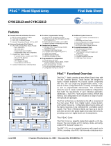
1. Introduction
Thank you for your interest in the CY3280-MBR3 Evaluation Kit (EVK). This kit is designed to show-
case the abilities of the CY8CMBR3116 register-configurable CapSense
®
controller. It is also
designed as an Arduino™-compatible shield that supports various Arduino baseboards as well as
other stackable shields available in the market. The CY3280-MBR3 EVK features four CapSense
buttons, one proximity sensor loop, LEDs, a buzzer, and an onboard USB-I
2
C bridge to communi-
cate with the EZ-Click™ software tool, which configures the CY8CMBR3xxx controller.
The CY8CMBR3xxx series is the latest addition to the register-configurable CapSense Mechanical
Button Replacement (MBR) family of solutions. The CY8CMBR3xxx family of controllers enables
you to quickly and easily add capacitive touch sensing to your user interface. See Configuring the
CY8CMBR3116 Controller Using EZ-Click on page 18 for information on how to configure a CY8CM-
BR3116 controller. CY3280-MBR3 offers the best features of Cypress’ CapSense in a small package
that is easy to implement and configure. Coupled with the Capacitive Sigma Delta PLUS (CSD
PLUS) sensing algorithm and the patented SmartSense™ Auto-Tuning feature, the CY8CMBR3xxx
controller provides a robust capacitive sensing solution, with up to 16 CapSense inputs.
SmartSense Auto-Tuning has the following advantages:
■ Reduces design effort by eliminating manual tuning
■ Adapts to variations in PCB, overlay, paint, and manufacturing that degrade touch-sensing per-
formance
■ Eliminates manual tuning in production
■ Adapts to changes in the system environment due to noise
■ Allows a platform design approach with different overlays, button shapes, and trace lengths
The MBR3 solution delivers a high signal-to-noise ratio (SNR) even in extremely noisy environments
and maintains optimal sensor performance at run time. The driven shield capability offers robust
proximity sensing and water tolerance, enabling its use in a wide range of applications. The MBR3
solution supports register configurability and SmartSense Auto-Tuning features, which allow cus-
tomers to gain a faster time-to-market for their end product.
The CY8CMBR3xxx family of controllers is designed with multiple low-power operational states to
meet the low-power requirements of battery-powered applications. These controllers have the fol-
lowing operational states: Boot, Active, Look-for-Touch, Look-for-Proximity, Deep Sleep, and Config-
uration. The CY8CMBR3xxx controllers automatically manage transitions between the four states.
The Look-for-Proximity state allows ultra-low power consumption when a human body is not in close
proximity. This state is entered only if the wake-on-approach feature is enabled (and toggle is dis-
abled) in the MBR3 register configuration, which can be done using EZ-Click. Refer to the MBR3
device datasheet for more details on the CY8CMBR3xxx family of CapSense controllers.
The kit package includes EZ-Click, which is required to configure the kit. For more information and to
download the tool, visit the EZ-Click webpage.

CY3280-MBR3 Evaluation Kit User Guide, Doc. #: 001-89905 Rev. *G 8
Introduction
1.1 Kit Contents
The CY3280-MBR3 EVK includes the following components (see Figure 1-1):
■ CY3280-MBR3 EVK with a 2-mm overlay
■ One additional overlay of 1-mm thickness
■ A to Mini-B USB cable
■ Water dropper
Figure 1-1. Kit Contents
Inspect the contents of the kit. If you find any part missing, contact your nearest Cypress sales office
for help: www.cypress.com/go/support.
1.2 Getting Started
This kit guide helps to familiarize you with the CY3280-MBR3 EVK. The Kit Installation chapter on
page 11 describes the installation of the EVK software. The Kit Operation chapter on page 14
explains how to configure the CY8CMBR3116 controller on the kit to test different features using
EZ-Click. The hardware details, and configuration files and example projects are explained in their
respective chapters. The configuration files and example projects require EZ-Click and PSoC Cre-
ator™, respectively. The Advanced Topics chapter on page 70 describes how to use the Bridge Con-
trol Panel (BCP) to configure the MBR3 device. The Appendix on page 76 provides the schematics,
board layout, pin assignment, and the bill of materials (BOM).

CY3280-MBR3 Evaluation Kit User Guide, Doc. #: 001-89905 Rev. *G 9
Introduction
1.3 Factory Default Configuration
The kit installation folder includes three configuration files that demonstrate several features of the
CY8CMBR3116 CapSense controller. See Configuration Files on page 46 for more details. The
CY3280-MBR3 EVK is configured with the Water Tolerance configuration by default. In this configu-
ration, water tolerance, flanking sensor suppression (FSS), and auto-reset features are enabled for
four CapSense buttons. The LEDs are also enabled to provide visual feedback for CapSense button
touch. For more details on configuring the MBR3 device, refer to the EZ-Click User Guide, available
at <Install_Directory>\EZ-Click\<version>\Documentation.
1.4 Additional Learning Resources
Visit the CY8CMBR3116 CapSense Controller page for additional learning resources.
Visit the CY8CMBR3xxx CapSense Design Guide page for additional Host API-based demo
projects.
Visit the CapSense Code Examples page for the list of code examples using CapSense controllers.
1.5 Technical Support
For assistance, go to our support web page, or contact our customer support at +1(800) 541-4736
extension 2 (in the USA), or +1 (408) 943-2600 extension 2 (International).
1.6 Acronyms
Table 1-1. Acronyms Used in the Document
Acronyms Definition
BCP Bridge Control Panel
BOM bill of materials
CS capacitive sensor
CSD CapSense sigma delta
ESD electrostatic discharge
EVK evaluation kit
FSS flanking sensor suppression
GPO general-purpose output
GUI graphical user interface
IIC/I
2
C
inter-integrated circuit
LED light-emitting diode
MBR mechanical button replacement
NC not connected
PC personal computer
PCB printed circuit board
PSoC
®
Programmable System-On-Chip
SNR signal-to-noise ratio
UART universal asynchronous receiver/transmitter
USB universal serial bus

CY3280-MBR3 Evaluation Kit User Guide, Doc. #: 001-89905 Rev. *G 10
Introduction
1.7 Document Conventions
Table 1-2. Document Conventions for Guides
Convention Usage
Courier New Displays file locations, user entered text, and source code:
C:\...cd\icc\
Italics Displays file names and reference documentation:
Read about the sourcefile.hex file in the PSoC Designer User Guide.
[Bracketed, Bold] Displays keyboard commands in procedures:
[Enter] or [Ctrl] [C]
File > Open Represents menu paths:
File > Open > New Project
Bold Displays commands, menu paths, and icon names in procedures:
Click the File icon and then click Open.
Times New Roman Displays an equation:
2 + 2 = 4
Text in gray boxes Describes Cautions or unique functionality of the product.

CY3280-MBR3 Evaluation Kit User Guide, Doc. #: 001-89905 Rev. *G 11
2. Kit Installation
This chapter describes the CY3280-MBR3 EVK software installation and the prerequisites.
2.1 Before You Begin
All Cypress software installations require administrator privileges, but these are not required to run
the software after it is installed. Close any other Cypress software that is currently running before
installing the kit software.
2.2 CY3280-MBR3 EVK Software
The kit requires Cypress' proprietary software, such as PSoC Programmer (3.24.2 or later) and
EZ-Click (2.0 SP2 or later), and generic software such as .NET Framework, Windows Installer, and
Internet Explorer. The CY3280-MBR3 software is available on the kit web page in three formats:
Notes:
■ Adobe Reader is required to view kit documents. If Adobe Reader is not installed on your PC, the
installer provides the link to download and install it.
■ PSoC Creator is required to execute the PSoC 4 host example projects shipped with the kit.
However, it is not a mandatory prerequisite and is not installed along with the kit contents. You
can download and install PSoC Creator from www.cypress.com/go/psoccreator.
Table 2-1. Kit Software Formats
Install Package File Format Usage
CY3280-MBR3 Kit ISO ISO
This package can be used if the PC does not have any Cypress or non-
Cypress prerequisite software installed. It first installs the prerequisites
and then the kit content (firmware, hardware, and documentation files) in
the specified location.
CY3280-MBR3 Kit Setup EXE
This package can be used if the PC does not have any Cypress prerequi-
site software installed. If any non-Cypress prerequisites are found to be
missing during installation, the installer provides links to download and
install them and then installs the kit content (firmware, hardware, and
documentation files) in the specified location.
CY3280-MBR3 Kit Only EXE
This package can be used if the PC has all the Cypress and non-Cypress
prerequisites installed. It installs only the kit content (firmware, hardware,
and documentation files) in the specified location. If any of the prerequi-
sites are found missing during the installation process, the installer
prompts you to install all the required software before attempting to install
the kit. The installer redirects to the kit web page to download and install
any missing Cypress software. Similarly, it provides links to download
and install the missing non-Cypress prerequisites.

CY3280-MBR3 Evaluation Kit User Guide, Doc. #: 001-89905 Rev. *G 12
Kit Installation
2.3 Install the Software
1. Run cyautorun.exe in the kit ISO to start the installation process.
2. Click Install CY3280-MBR3 EVK to start the kit installation; see Figure 2-1.
Figure 2-1. Kit Installer Startup Screen
3. Select the folder to install the CY3280-MBR3 EVK files. Choose the directory and click Next, as
shown in Figure 2-2. The installation directory is referred to as <Install_Directory> in this
document.
Figure 2-2. Default Path for EVK Installation

CY3280-MBR3 Evaluation Kit User Guide, Doc. #: 001-89905 Rev. *G 13
Kit Installation
4. When you click Next, the CY3280-MBR3 Kit ISO installer automatically installs the required soft-
ware, if it is not present on your computer.
5. Select the installation type (see Figure 2-3). The drop-down menu contains three options:
Typical (installs all the required features), Custom (lets you choose the features to be installed),
and Complete (installs all the contents). Click Next after you select the installation type.
Note: It is recommended that you choose the Complete installation type.
Figure 2-3. Installation Type Options
6. Accept the End-User License Agreement and click Next to proceed with the installation.
7. When the installation begins, a list of packages appears on the installation page. A green check
mark appears adjacent to every package after successful installation.
8. Enter your contact information or select the Continue Without Contact Information check box.
9. Click Finish to complete the CY3280-MBR3 EVK software installation.
After the installation is complete, the kit contents are available at the following location:
<Install_Directory>\CY3280-MBR3 EVK\<version>
2.4 Uninstall the Software
You can uninstall the CY3280-MBR3 EVK software using one of the following methods:
■ Go to Start > All Programs > Cypress > Cypress Update Manager > Cypress Update Man-
ager; select the Uninstall button corresponding to the kit software.
■ Go to Start > Control Panel > Programs and Features; select the Uninstall/Change button
corresponding to the kit software.

CY3280-MBR3 Evaluation Kit User Guide, Doc. #: 001-89905 Rev. *G 14
3. Kit Operation
The CY8CMBR3116 CapSense controller is a register-configurable device that supports multiple
features, as listed in Kit Features on page 24. The CY3280-MBR3 EVK hardware includes four Cap-
Sense buttons, a proximity sensor loop, a buzzer, and LEDs; it can be used to demonstrate all the
features of the MBR3 device.
The CY3280-MBR3 EVK enables you to develop applications using the CY8CMBR3116 controller.
Figure 3-1 and Figure 3-2 illustrate the onboard components of the CY3280-MBR3 EVK.
Figure 3-1. CY3280-MBR3 EVK Top View
USB connector
Kit current measurement jumper
on the reverse of the board
Slide switch to increase
capacitance on BTN2
Reset switch
Status LED
Power LED
CapSense buttons with 10-mm
diameter and LED at the center
Proximity LED
Proximity loop
CapSense buttons with 11-mm
diameter and LED at the center

CY3280-MBR3 Evaluation Kit User Guide, Doc. #: 001-89905 Rev. *G 15
Kit Operation
Figure 3-2. CY3280-MBR3 EVK Bottom View
Arduino headers
SlideswitchSW1
(capacitance selector
switch for BTN2)
Slide switch SW3
(trace selection
switch for BTN4)
Buzzer
I2C selection jumpers
Buzzer, Shield, and Host
Interrupt selection jumpers
PSoC 5LP USB-I2C bridge
CY8CMBR3116 CapSense
Express controller
MBR3 current
measurement jumper
Reset switch
USB connector
Kit current
measurement jumper

CY3280-MBR3 Evaluation Kit User Guide, Doc. #: 001-89905 Rev. *G 16
Kit Operation
3.1 Powering the Kit
To power the kit, connect the A to Mini-B USB cable, provided with the kit, to your PC or laptop. The
kit enumerates as a composite device (see Tab l e 3-1 ), and three separate devices appear under the
Device Manager (Start > Control Panel > Device Manager) option of the Windows operating sys-
tem, as shown in Figure 3-5.
Table 3-1. CY3280-MBR3 Evaluation Kit in Device Manager after Enumeration
Note: Although the kit supports a programmer and a UART bridge, these functionalities are not used
with this kit. Do not use PSoC Programmer to communicate with the PSoC 5LP on the kit, as it may
corrupt the kit firmware.
Figure 3-3. KitProg Driver Installation
Figure 3-4. KitProg Driver Installation Complete
After the driver installation is complete, all the above devices are listed in the Device Manager, as
shown in Figure 3-5.
Port Description
USB input device
USB-I
2
C bridge
KitProg programmer Programmer and debugger
KitProg USB-UART USB-UART bridge appears as COM# port

CY3280-MBR3 Evaluation Kit User Guide, Doc. #: 001-89905 Rev. *G 17
Kit Operation
Figure 3-5. Device Manager View after KitProg is Installed
Note: The Device Manager may have more than one instance of ‘USB Input Device' and 'USB Com-
posite Device', based on the number of USB devices connected to your PC. The USB Input Device
and USB Composite Device installed with KitProg can be identified by the hardware IDs (VID and
PID); these devices will have hardware IDs 0x4B4 and 0xF139. To find the hardware ID, right-click
on the device and select Properties. In the Details tab, select Hardware IDs from the Property field
drop-down menu.
Wait until the USB enumeration completes successfully and the board is powered. When the USB
enumeration is successful, both the power LED and status LED light up.
The kit is programmed with the Water Tolerance configuration by default. See Water Tolerance on
page 53 for more information.

CY3280-MBR3 Evaluation Kit User Guide, Doc. #: 001-89905 Rev. *G 18
Kit Operation
3.2 Communication Between PC Host and Kit
The kit includes PSoC 5LP, an ARM-based PSoC that functions as a USB-I
2
C bridge between the
CY8CMBR3116 controller and the PC host (see Figure 3-6). The CY8CMBR3116 controller commu-
nicates with PSoC 5LP using an I
2
C interface, and the PSoC 5LP transfers the data over USB to the
PC and EZ-Click.
Figure 3-6. Block Diagram - Communication Between PC Host and Kit
Cypress provides two USB-I
2
C software utilities: EZ-Click and Bridge Control Panel (BCP). The
CY3280-MBR3 EVK uses EZ-Click for register configuration. BCP is the software provided by
Cypress that allows you to communicate over I
2
C, SPI, or RX8 using your PC and USB. This appli-
cation currently supports CY3240, MiniProg3, FirstTouch, FirstTouchRF, TrueTouchBridge, DVK-
Prog1, and KitProg bridges. See Using PSoC 5LP as USB-I2C Bridge on page 70 for more details
on using the BCP.
You should install EZ-Click on the PC to evaluate the kit features. This software is part of the kit
installer, but it can also be downloaded from www.cypress.com/go/CY3280-MBR3. You can use
EZ-Click to configure the CapSense controllers using I
2
C communication over the USB-I
2
C bridge.
You can also use it to monitor raw count, baseline, SNR, and other CapSense sensor-related infor-
mation directly.
3.3 Configuring the CY8CMBR3116 Controller Using EZ-Click
Follow these steps to configure the CY8CMBR3116 controller:
1. Connect the CY3280-MBR3 EVK to the PC via the USB port using the USB cable.
2. Open EZ-Click from the default location: Start > All Programs > Cypress > EZ-Click <version>
> EZ-Click <version>.
3. Create a new project in EZ-Click by clicking New Project… in the File menu, as shown in
Figure 3-7.
Figure 3-7. Creating a New Project in EZ-Click
PC Host
I2C Commands
through USB
EZ-Click
B1
B2
B3
B4
LED1
Prox
Loop
Buzz
Shield
PSoC 5LP
as USB-
I2C Bridge
MBR3
I2C Commands
LED2
LED3 LED4LED5

CY3280-MBR3 Evaluation Kit User Guide, Doc. #: 001-89905 Rev. *G 19
Kit Operation
4. Enter an appropriate name for the project and choose a location to save your project. Select Tar-
get Device as ‘CY8CMBR3116-LQXI’ from the Product Selector. To launch the Product Selector,
click the Device Selector button, as shown in the following figure.
Figure 3-8. New Project Details
Figure 3-9. Choosing Part Number in Product Selector Guide
5. Ensure that the I
2
C selection jumpers J13 and J14 are shorted between pins 1 and 2 to allow
communication with the onboard PSoC 5LP USB-I
2
C bridge.
6. Connect the kit to EZ-Click by clicking the Select Target Device button ( ) on the EZ-Click tool
bar. This opens a Select I2C Target window (Figure 3-10); select the following:
a. KitProg/<kit number> in the Ports window.
b. The I
2
C slave device in the Devices window.
Note: The CY8CMBR3116 has a slave address of 0x37 by default. If multiple slave devices
are connected, you can disconnect from one slave and connect to another by using the Con-
nect/Disconnect button in the Select I2C Target window. See Figure 3-10.
c. Select the speed of the I
2
C communication as 400 kHz.
d. Choose the target device voltage by selecting the 3.3 V radio button.

CY3280-MBR3 Evaluation Kit User Guide, Doc. #: 001-89905 Rev. *G 20
Kit Operation
Figure 3-10. Connecting the Kit Using EZ-Click
7. Click OK. The I
2
C slave address of the connected device appears on the status bar at the bottom
of the EZ-Click window, as shown in Figure 3-11.
Figure 3-11. I
2
C Slave Address Display
8. Enable the button sensors in the CapSense sensor configuration tab, as shown in Figure 3-12.
See Pin Mapping Between CY8CMBR3116 and CY3280-MBR3 EVK on page 31 to learn about
the available button sensors and how they are connected to the CY8CMBR3116 device. In this
example, all four available button sensors on the kit are enabled.
/