Page is loading ...

198 Champion Ct., San Jose, CA 95134
408.943.2600, www.cypress.com
If you have questions, call the
Applications Hot Line 425.787.4814
www.cypress.com/support
©2008 Cypress Semiconductor Corporation
Doc. # 001-44863 Rev. *A
CapSense™, PSoC Designer™, Programmable System-on-Chip™, and PSoC Express™ are trademarks
and PSoC® is a registered trademark of Cypress Semiconductor Corp. All other trademarks or registered
trademarks referenced herein are property of the respective corporations.
Additional CapSense Kits
For more information on these kits, please go to www.cypress.com/CapSense.
Evaluation Kits Development Kit
CapSense
Express: Quickest
and Easiest to Use
Touch Sensing
CY3218
CAPEXP1/CAPEXP3
For Buttons
(Up to 10 or 4 IOs)
CY3218
CAPEXP2
For Sliders
(Up to 10 IOs)
CY3280-BK1
Universal CapSense
CapSense:
Programmable
Touch Sensing
CY3203A
CapSense CSA
CapSense Plus:
CapSense with Non-
Touch Sensing
Functionality (Motor
Control, Power
Management, Gyro
Sensing, etc.)
CY3213A
CapSense CSD
CY3214
PSoCEvalUSB
Doc. # 001-44863 Rev. *A
Cypress Semiconductor
198 Champion Court
San Jose, CA 95134-1709
Phone (USA): 800.858.1810
Phone (Intnl): 408.943.2600
http://www.cypress.com
CY3218-CAPEXP2 CapSense™ Express
Evaluation Kit Quick Start

Getting Started
1. Review Kit Contents
2. Explore the Board
3. Install Software
4. CY3218-CAPEXP2 Board Features
5. Tune the CY3218-CAPEXP2 CapSense Express Board
6. Create a CY3218-CAPEXP2 CapSense Express Project
7. Additional CapSense Resources
1. Review Kit Contents
Each CY3218-CAPEXP2 CapSense Express Demonstration Kit contains:
■ CY3218-CAPEXP2 CapSense Express Demonstration Board
■ Kit CD, which includes:
❐ PSoC Programmer
❐ .NET Framework 2.0 (for Windows 2000 and Windows XP)
❐ PSoC Express 3
❐ CapSense Express Extension Pack
❐ CapSense Express Kit Documentation
■ Retractable USB Cable (A to Mini-B)
■ PSoC CY3240-I2USB Bridge Board
■ AAA Battery
2. Explore the Board
2.1. Insert the AAA battery into the battery holder on the back of the board.
2.2. Remove the jumper from J2 (back of board, left side, center).
2.3. Slide your finger across the slider. Notice how the LEDs illuminate in a clockwise direction
as you move your finger from the left to the right across the slider.
2.4. Press the mechanical button at the bottom of the board. All four LEDs light up.
2.5. Turn the board off by replacing the jumper on J2. Note that replacing the jumper disables
battery operation.
Caution: Do not touch the board anywhere other than the edges or the
buttons. Touching the board in the wrong area could lead to a short and an
unresponsive board. If this happens, follow the instructions in Section 2 to
reset the power to the board.
CapSense Technical Articles
■ Designer's Guide to Rapid Prototyping of Capacitive Sensors on any Surface
■ Controls & Sensors Touch Sensors Spread Out
■ White Paper Cypress’s CapSense Successive Approximation Algorithm
■ The Art of Capacitive Touch Sensing
Design Support
PSoC Development Software Online
All PSoC development software tools are available for download online. For PSoC Express,
visit www.cypress.com/psocexpress. For PSoC Designer visit www.cypress.com/psocdesigner.
For PSoC Programmer visit www.cypress.com/psocprogrammer.
PSoC Device Selector Guide
In the PSoC Application Notes section, search for AN2209—The Device Selection Guide for
PSoC. It is a useful tool for determining exactly which PSoC device you should use for a specific
design project.
PSoC Development Tools Selector Guide
In the PSoC Application Notes section, search for AN2402—The PSoC Development Tools
Selector Guide. This is a complete catalog and description of all the development tools that sup-
port PSoC devices and when to use them in your design cycle—from concept to production.
PSoC On-Demand Training
Visit www.cypress.com/psoctraining to engage in on-demand self-paced PSoC product and
development software training. Learn to design PSoC like the pros, at the introductory, interme-
diate, and advanced knowledge levels!
PSoC On-Site Training
Email [email protected] to enquire about PSoC in-person training seminars at a location
near you. Learn design basics, tips, and tricks from the pros to become a PSoC design expert!
Online Technical Support
For knowledge base articles, customer forums, and online application support, visit
www.cypress.com/support.
Page 2 Page 19

7. Additional CapSense Resources
PSoC Data Sheets, Application Notes and Technical Articles
Cypress provides a wealth of information about CapSense Express, and more is frequently
added. Many sample documents, schematics, layouts, guidelines, and other CapSense
Express documents are available on the CD and at www.cypress.com (except where indicated).
To find documentation online:
a. Go to www.cypress.com.
b. Click on the Documentation link.
c. Select the type of documentation you are looking for from the Resource Types list.
d. Type the part number or document number into the Search in Design Resources
field.
e. Click the Search button .
CapSense Express DataSheets (available on www.cypress.com)
■ CY8C20110 Up to 10 IOs for touch sensing buttons, LEDs, and GPIOs
■ CY8C201A0 Up to 10 IOs for touch sensing buttons/sliders, LEDs, and GPIOs
■ CY8C20180 Up to 8 IOs for touch sensing buttons, LEDs, and GPIOs
■ CY8C20160 Up to 6 IOs for touch sensing buttons, LEDs, and GPIOs
■ CY8C20140 Up to 4 IOs for touch sensing buttons, LEDs, and GPIOs (16-Pin QFN/SOIC)
■ CY8C20142 Up to 4 IOs for touch sensing buttons, LEDs, and GPIOs (8-Pin SOIC)
CapSense Application Notes
■ AN44207, CapSense Express - API’s for Register Configuration (available on
www.cypress.com)
■ AN44208, CapSense Express - I2C Communication Timing Information (available on
www.cypress.com)
■ AN42137, CapSense Express Software Tool
■ AN44203, Configuring CapSense Express in Production
■ AN44209, CapSense Express Power and Sleep Considerations
■ AN2292, Layout Guidelines for PSoC™ CapSense
■ AN2318, EMC Design Considerations for PSoC CapSense Applications
■ AN2394, CapSense Best Practices
■ AN2397, CapSense Data Viewing Tool
■ AN2403, Signal-to-Noise Ratio Requirement for CapSense Applications
■ AN14459, CapSense Device and Method Selection Guide
3. Install Software
Install PSoC Express Development Software
3.1. Insert the Kit CD, wait for the installer to start, and install the following software in the order
listed:
a. Install PSoC Programmer.
b. Install .NET Framework 2.0.
c. Install PSoC Express 3.
d. Install CapSense Express Extension Pack.
e. Install CapSense Express Kit Documentation.
4. CY3218-CAPEXP2 Board Features
■ One 5-Segment CapSense
Slider
■ 4 Status LEDs (Green)
■ 1 Power LED (Red)
■ 1 Mechanical Switch
■ I
2
C Header
■ AAA Battery Holder
Use the CY3218-CAPEXP2 Evaluation Kit to evaluate the CapSense slider, LED drive, digital
input, and I2C features of the CapSense Express device. Via the CapSense Express Configura-
tion Tool in PSoC Express, the four status LEDs can be controlled by the CapSense slider and
the mechanical button. The CapSense Express device mounted on the board is in the 16-QFN
package. The board is powered with a AAA battery mounted in the battery holder. A boost con-
verter converts the input voltage in the range of 0.9V-1.5V to the device operating voltage of
3.3V. The board can also be powered using an I2C to USB bridge connected to the I2C header.
Top of Board
CapSense Slider
Status LEDs
Mechanical Button
Page 18 Page 3

5. Tune the CY3218-CAPEXP2 CapSense Express Board
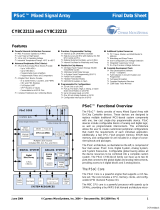
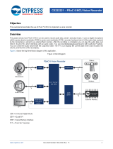
Functional Description
When a finger moves along the capacitive slider, corresponding LEDs are lit in a circular pro-
gression. Additionally, pressing the pushbutton switch causes all of the LEDs to be lit.
Tuning Steps
5.1. Connect your computer to the CapSense test board ISSP Connector (J5) using the
CY3240-I2USB Bridge Board and a USB cable. When connected correctly, the USB con-
nector on the CY3240-I2USB Bridge Board is visible when viewing the front of the
CY3218-CAPEXP2 board.
5.2. Launch PSoc Express.
Front of Board
Mini USB Port
6.22. In the Pin Specific Tuning pane, check Show Differences.
6.23. Slowly move your finger from left to right across the slider. The LEDs light clockwise start-
ing with the topmost LED on the board.
6.24. Press the mechanical button. All LEDs light at the same time.
What’s Next
Congratulations! You have successfully recreated the factory installed program used in Section
5. To experiment with slider and LED behavior, select any LED (G3 through G8) from the Select
Pin menu in the Pin Specific Tuning pane and set different slider segments to light different
LEDs. You can also reverse the inversion so that an LED is on until a button is pressed. To tune
the CapSense slider, follow the steps listed in Section 5.
Page 4 Page 17

5.3. From the Express Design Catalog, open the CY3218 CAPEXP2 CapSense Express Kit
folder.
5.4. Double-click 5 Segment CapSense Slider to open the design.
5.5. Name the design FiveSegmentSlider and save the design in the location of your choice.
5.6. Click Monitor to open the Monitor view.
5.7. The Monitor Status indicator shows Connected .
5.8. Right-click Input1 and select Show Tuner.
The Monitor Status indicator changes to Running , and the CapSense Express win-
dow opens.
5.9. If your board is programmed with another design, click Apply to board in the
lower-right area of the CapSense Express window. When the Configure through USB2IIC
Bridge status dialog appears, click OK. If your board is already programmed with the cor-
rect design, the Apply to board button is grayed out.
6.17. Click OK to close the User Pin Assignment window.
6.18. Click Apply to board. Wait for the Configure through USB2IIC Bridge status window
appears and click OK.
6.19. Click OK to close the CapSense Express CapSense Express 5 Segment / Slider 5 GPIO :
Slider window.
Monitor the Board
6.20. In the Design pane, select Monitor. The Monitor Status indicator shows Connected
.
6.21. Right-click Slider and select Show Tuner.
The Monitor Status indicator changes to Running , and the CapSense Express 5
Segment / Slider 5 GPIO : Slider window opens.
Driver Pin
Sldr1 (Sldr0) GP0[4]
Sldr2 (Sldr1) GP0[3]
Sldr3 (Sldr2) GP0[2]
Sldr4 (Sldr3) GP1[4]
Sldr5 (Sldr4) GP1[3]
Output1 (G0) GP0[1]
Output2 (G1) GP0[0]
Output3 (G2) GP1[0]
Output4 (G3) GP1[1]
Input1 (G4) GP1[2]
Page 16 Page 5

5.10. Test the board by moving your finger across the slider. The LEDs above the slider turn on
each time the corresponding slider segment is touched. Press the mechanical button at
the bottom of the board to turn on all four LEDs.
Notice how the Pin Status and Latched Value indicators change from OFF to ON when a
slider segment is touched.
5.11. Press the mechanical button at the bottom of the board to turn on all four LEDs.
Tune the Slider
5.12. From the Select Pin menu, select Slider.
5.13. Check Show Differences.
6.16. Assign each CapSense slider segment, LED, and mechanical button to the pin annotated
on the board. For example, the leftmost slider segment, Sldr1, is labeled GP0[3].
Drag each driver from the Unassigned list to the appropriate pin (listed on page 16 for con-
venience).
GP0[3]
GP1[4] GP0[4] GP1[3]
GP0[2]
Page 6 Page 15

6.13. To assign the rest of the slider segments to the other LEDs, simply select each LED from
the Select Pin menu, and click on the appropriate slider segment, and the G4 mechanical
button. Remember to click the square box so the invert symbol is showing. Control the
LEDs with the slider segments mechanical button according to the following table:
Assign Drivers to Pins
6.14. In the upper-left of the window, click the Pin Assignment (16-SOIC) button. The User Pin
Assignment window opens.
6.15. Select the 16 pin QFN part for the Pin Package Type.
LED Control
G0 Sldr0, Sldr4, & G4
G1 Sldr1 & G4
G2 Sldr2 & G4
G3 Sldr3 & G4
5.14. Slide your finger across the slider. Notice the difference bars above the green position bar.
Also notice how the LEDs illuminate in a clockwise direction as you move your finger from
the left to the right across the slider.
5.15. Cover the slider with a piece of paper and then touch the slider (with the paper between
our finger and the slider). Notice how the Difference Count Value changes. Add additional
pieces of paper to increase the thickness over the button. With enough sheets of paper
added, the Difference variable does not rise above the Finger Threshold, and the button
does not register a Hit. With 16 sheets of paper over the slider, the difference bars are very
low and the LEDs do not light up.
Page 14 Page 7

5.16. Change the IDAC setting for each segment from 14 to 5, and click Apply to board.’
5.17. Cover the slider with the paper again, and touch the slider. The difference bars are now
higher. If the LEDs do not light, keep adjusting the IDAC settings lower until the LEDs light
reliably.
5.18. Experiment with other materials such as plastic and wood.
What’s Next
Now that you know how easy it is to tune a CapSense slider with PSoC Express, learn how to
create the project from scratch in Section 6.
6.11. Since there are four LEDs and five slider segments, have the LED G0 turn on when the
first and last slider segments are touched. To do this, simply click on the yellow Sldr4 box.
6.12. To have the LED G0 turn on when the mechanical button is pressed, click the yellow G4
box.
Invert Symbol
Connecting Line
Default = LED Off
Invert Symbol
Connecting Line
Default = LED Off
Page 8 Page 13

6.10. To assign an LED to a CapSense slider segment, simply click on the yellow box of the
CapSense slider segment you want to assign to LED G0. For LED driver G0, select the
CapSense slider segment Sldr0. A small line will then connect C0 to the purple OR box.
To have the LED turn on when the slider segment is touched, click the little box to the right
of the purple OR box. This will change the square to an invert symbol.
Invert Symbol
Connecting Line
Default = LED Off
6. Create a CY3218-CAPEXP2 CapSense Express Project
Start the Project
6.1. Connect your computer to the CapSense test board I
2
C Connector (J5) using the
CY3240-I2USB Bridge Board and a USB cable. When connected correctly, the USB con-
nector on the CY3240-I2USB Bridge Board is visible when viewing the front of the
CY3218-CAPEXP2 board.
6.2. Launch PSoc Express.
6.3. Click New Project, name the project FiveSegmentSlider, and save the design in the
location of your choice.
6.4. Select View > Driver Catalog.
6.5. At the bottom of the Driver Catalog, select the Inputs Tab.
6.6. Open the CapSense Express directory, right-click the 5 Segment Slider 5 GPIO driver,
and select Add to Design. The Add Input Driver window opens.
Front of Board
Mini USB Port
Page 12 Page 9

6.7. Name the driver Slider and click OK. The CapSense Express 5 Segment / Slider 5 GPIO :
Slider window opens.
In PSoC Express, each CapSense slider, LED, and mechanical button requires a separate
driver. The 5 Segment Slider 5 GPIO driver is a special driver that allows you to configure
the slider, LED, and mechanical button in one interface. Each driver is listed in the Config-
ure Local Parameters pane.
Configure the Drivers
6.8. By default, all driver types in the Configure Local Parameters pane are set to CapSense
Slider Sensor. To setup the LEDs, set the Pin Type for drivers C0 through C3 to GPOutput
and the Drive Mode for each of those drivers to Strong Drive.
To setup the mechanical button, set the Pin Type for driver G4 to GPInput. Set the Drive
Mode to Open Drain Low.
Configure Slider and LED Behavior
6.9. In the Pin Specific Tuning pane, choose G0 from the Select Pin menu.
Page 10 Page 11

6.10. To assign an LED to a CapSense slider segment, simply click on the yellow box of the
CapSense slider segment you want to assign to LED G0. For LED driver G0, select the
CapSense slider segment Sldr0. A small line will then connect C0 to the purple OR box.
To have the LED turn on when the slider segment is touched, click the little box to the right
of the purple OR box. This will change the square to an invert symbol.
Invert Symbol
Connecting Line
Default = LED Off
6. Create a CY3218-CAPEXP2 CapSense Express Project
Start the Project
6.1. Connect your computer to the CapSense test board I
2
C Connector (J5) using the
CY3240-I2USB Bridge Board and a USB cable. When connected correctly, the USB con-
nector on the CY3240-I2USB Bridge Board is visible when viewing the front of the
CY3218-CAPEXP2 board.
6.2. Launch PSoc Express.
6.3. Click New Project, name the project FiveSegmentSlider, and save the design in the
location of your choice.
6.4. Select View > Driver Catalog.
6.5. At the bottom of the Driver Catalog, select the Inputs Tab.
6.6. Open the CapSense Express directory, right-click the 5 Segment Slider 5 GPIO driver,
and select Add to Design. The Add Input Driver window opens.
Front of Board
Mini USB Port
Page 12 Page 9

5.16. Change the IDAC setting for each segment from 14 to 5, and click Apply to board.’
5.17. Cover the slider with the paper again, and touch the slider. The difference bars are now
higher. If the LEDs do not light, keep adjusting the IDAC settings lower until the LEDs light
reliably.
5.18. Experiment with other materials such as plastic and wood.
What’s Next
Now that you know how easy it is to tune a CapSense slider with PSoC Express, learn how to
create the project from scratch in Section 6.
6.11. Since there are four LEDs and five slider segments, have the LED G0 turn on when the
first and last slider segments are touched. To do this, simply click on the yellow Sldr4 box.
6.12. To have the LED G0 turn on when the mechanical button is pressed, click the yellow G4
box.
Invert Symbol
Connecting Line
Default = LED Off
Invert Symbol
Connecting Line
Default = LED Off
Page 8 Page 13

6.13. To assign the rest of the slider segments to the other LEDs, simply select each LED from
the Select Pin menu, and click on the appropriate slider segment, and the G4 mechanical
button. Remember to click the square box so the invert symbol is showing. Control the
LEDs with the slider segments mechanical button according to the following table:
Assign Drivers to Pins
6.14. In the upper-left of the window, click the Pin Assignment (16-SOIC) button. The User Pin
Assignment window opens.
6.15. Select the 16 pin QFN part for the Pin Package Type.
LED Control
G0 Sldr0, Sldr4, & G4
G1 Sldr1 & G4
G2 Sldr2 & G4
G3 Sldr3 & G4
5.14. Slide your finger across the slider. Notice the difference bars above the green position bar.
Also notice how the LEDs illuminate in a clockwise direction as you move your finger from
the left to the right across the slider.
5.15. Cover the slider with a piece of paper and then touch the slider (with the paper between
our finger and the slider). Notice how the Difference Count Value changes. Add additional
pieces of paper to increase the thickness over the button. With enough sheets of paper
added, the Difference variable does not rise above the Finger Threshold, and the button
does not register a Hit. With 16 sheets of paper over the slider, the difference bars are very
low and the LEDs do not light up.
Page 14 Page 7

5.10. Test the board by moving your finger across the slider. The LEDs above the slider turn on
each time the corresponding slider segment is touched. Press the mechanical button at
the bottom of the board to turn on all four LEDs.
Notice how the Pin Status and Latched Value indicators change from OFF to ON when a
slider segment is touched.
5.11. Press the mechanical button at the bottom of the board to turn on all four LEDs.
Tune the Slider
5.12. From the Select Pin menu, select Slider.
5.13. Check Show Differences.
6.16. Assign each CapSense slider segment, LED, and mechanical button to the pin annotated
on the board. For example, the leftmost slider segment, Sldr1, is labeled GP0[3].
Drag each driver from the Unassigned list to the appropriate pin (listed on page 16 for con-
venience).
GP0[3]
GP1[4] GP0[4] GP1[3]
GP0[2]
Page 6 Page 15

5.3. From the Express Design Catalog, open the CY3218 CAPEXP2 CapSense Express Kit
folder.
5.4. Double-click 5 Segment CapSense Slider to open the design.
5.5. Name the design FiveSegmentSlider and save the design in the location of your choice.
5.6. Click Monitor to open the Monitor view.
5.7. The Monitor Status indicator shows Connected .
5.8. Right-click Input1 and select Show Tuner.
The Monitor Status indicator changes to Running , and the CapSense Express win-
dow opens.
5.9. If your board is programmed with another design, click Apply to board in the
lower-right area of the CapSense Express window. When the Configure through USB2IIC
Bridge status dialog appears, click OK. If your board is already programmed with the cor-
rect design, the Apply to board button is grayed out.
6.17. Click OK to close the User Pin Assignment window.
6.18. Click Apply to board. Wait for the Configure through USB2IIC Bridge status window
appears and click OK.
6.19. Click OK to close the CapSense Express CapSense Express 5 Segment / Slider 5 GPIO :
Slider window.
Monitor the Board
6.20. In the Design pane, select Monitor. The Monitor Status indicator shows Connected
.
6.21. Right-click Slider and select Show Tuner.
The Monitor Status indicator changes to Running , and the CapSense Express 5
Segment / Slider 5 GPIO : Slider window opens.
Driver Pin
Sldr1 (Sldr0) GP0[4]
Sldr2 (Sldr1) GP0[3]
Sldr3 (Sldr2) GP0[2]
Sldr4 (Sldr3) GP1[4]
Sldr5 (Sldr4) GP1[3]
Output1 (G0) GP0[1]
Output2 (G1) GP0[0]
Output3 (G2) GP1[0]
Output4 (G3) GP1[1]
Input1 (G4) GP1[2]
Page 16 Page 5

5. Tune the CY3218-CAPEXP2 CapSense Express Board
Functional Description
When a finger moves along the capacitive slider, corresponding LEDs are lit in a circular pro-
gression. Additionally, pressing the pushbutton switch causes all of the LEDs to be lit.
Tuning Steps
5.1. Connect your computer to the CapSense test board ISSP Connector (J5) using the
CY3240-I2USB Bridge Board and a USB cable. When connected correctly, the USB con-
nector on the CY3240-I2USB Bridge Board is visible when viewing the front of the
CY3218-CAPEXP2 board.
5.2. Launch PSoc Express.
Front of Board
Mini USB Port
6.22. In the Pin Specific Tuning pane, check Show Differences.
6.23. Slowly move your finger from left to right across the slider. The LEDs light clockwise start-
ing with the topmost LED on the board.
6.24. Press the mechanical button. All LEDs light at the same time.
What’s Next
Congratulations! You have successfully recreated the factory installed program used in Section
5. To experiment with slider and LED behavior, select any LED (G3 through G8) from the Select
Pin menu in the Pin Specific Tuning pane and set different slider segments to light different
LEDs. You can also reverse the inversion so that an LED is on until a button is pressed. To tune
the CapSense slider, follow the steps listed in Section 5.
Page 4 Page 17

7. Additional CapSense Resources
PSoC Data Sheets, Application Notes and Technical Articles
Cypress provides a wealth of information about CapSense Express, and more is frequently
added. Many sample documents, schematics, layouts, guidelines, and other CapSense
Express documents are available on the CD and at www.cypress.com (except where indicated).
To find documentation online:
a. Go to www.cypress.com.
b. Click on the Documentation link.
c. Select the type of documentation you are looking for from the Resource Types list.
d. Type the part number or document number into the Search in Design Resources
field.
e. Click the Search button .
CapSense Express DataSheets (available on www.cypress.com)
■ CY8C20110 Up to 10 IOs for touch sensing buttons, LEDs, and GPIOs
■ CY8C201A0 Up to 10 IOs for touch sensing buttons/sliders, LEDs, and GPIOs
■ CY8C20180 Up to 8 IOs for touch sensing buttons, LEDs, and GPIOs
■ CY8C20160 Up to 6 IOs for touch sensing buttons, LEDs, and GPIOs
■ CY8C20140 Up to 4 IOs for touch sensing buttons, LEDs, and GPIOs (16-Pin QFN/SOIC)
■ CY8C20142 Up to 4 IOs for touch sensing buttons, LEDs, and GPIOs (8-Pin SOIC)
CapSense Application Notes
■ AN44207, CapSense Express - API’s for Register Configuration (available on
www.cypress.com)
■ AN44208, CapSense Express - I2C Communication Timing Information (available on
www.cypress.com)
■ AN42137, CapSense Express Software Tool
■ AN44203, Configuring CapSense Express in Production
■ AN44209, CapSense Express Power and Sleep Considerations
■ AN2292, Layout Guidelines for PSoC™ CapSense
■ AN2318, EMC Design Considerations for PSoC CapSense Applications
■ AN2394, CapSense Best Practices
■ AN2397, CapSense Data Viewing Tool
■ AN2403, Signal-to-Noise Ratio Requirement for CapSense Applications
■ AN14459, CapSense Device and Method Selection Guide
3. Install Software
Install PSoC Express Development Software
3.1. Insert the Kit CD, wait for the installer to start, and install the following software in the order
listed:
a. Install PSoC Programmer.
b. Install .NET Framework 2.0.
c. Install PSoC Express 3.
d. Install CapSense Express Extension Pack.
e. Install CapSense Express Kit Documentation.
4. CY3218-CAPEXP2 Board Features
■ One 5-Segment CapSense
Slider
■ 4 Status LEDs (Green)
■ 1 Power LED (Red)
■ 1 Mechanical Switch
■ I
2
C Header
■ AAA Battery Holder
Use the CY3218-CAPEXP2 Evaluation Kit to evaluate the CapSense slider, LED drive, digital
input, and I2C features of the CapSense Express device. Via the CapSense Express Configura-
tion Tool in PSoC Express, the four status LEDs can be controlled by the CapSense slider and
the mechanical button. The CapSense Express device mounted on the board is in the 16-QFN
package. The board is powered with a AAA battery mounted in the battery holder. A boost con-
verter converts the input voltage in the range of 0.9V-1.5V to the device operating voltage of
3.3V. The board can also be powered using an I2C to USB bridge connected to the I2C header.
Top of Board
CapSense Slider
Status LEDs
Mechanical Button
Page 18 Page 3

Getting Started
1. Review Kit Contents
2. Explore the Board
3. Install Software
4. CY3218-CAPEXP2 Board Features
5. Tune the CY3218-CAPEXP2 CapSense Express Board
6. Create a CY3218-CAPEXP2 CapSense Express Project
7. Additional CapSense Resources
1. Review Kit Contents
Each CY3218-CAPEXP2 CapSense Express Demonstration Kit contains:
■ CY3218-CAPEXP2 CapSense Express Demonstration Board
■ Kit CD, which includes:
❐ PSoC Programmer
❐ .NET Framework 2.0 (for Windows 2000 and Windows XP)
❐ PSoC Express 3
❐ CapSense Express Extension Pack
❐ CapSense Express Kit Documentation
■ Retractable USB Cable (A to Mini-B)
■ PSoC CY3240-I2USB Bridge Board
■ AAA Battery
2. Explore the Board
2.1. Insert the AAA battery into the battery holder on the back of the board.
2.2. Remove the jumper from J2 (back of board, left side, center).
2.3. Slide your finger across the slider. Notice how the LEDs illuminate in a clockwise direction
as you move your finger from the left to the right across the slider.
2.4. Press the mechanical button at the bottom of the board. All four LEDs light up.
2.5. Turn the board off by replacing the jumper on J2. Note that replacing the jumper disables
battery operation.
Caution: Do not touch the board anywhere other than the edges or the
buttons. Touching the board in the wrong area could lead to a short and an
unresponsive board. If this happens, follow the instructions in Section 2 to
reset the power to the board.
CapSense Technical Articles
■ Designer's Guide to Rapid Prototyping of Capacitive Sensors on any Surface
■ Controls & Sensors Touch Sensors Spread Out
■ White Paper Cypress’s CapSense Successive Approximation Algorithm
■ The Art of Capacitive Touch Sensing
Design Support
PSoC Development Software Online
All PSoC development software tools are available for download online. For PSoC Express,
visit www.cypress.com/psocexpress. For PSoC Designer visit www.cypress.com/psocdesigner.
For PSoC Programmer visit www.cypress.com/psocprogrammer.
PSoC Device Selector Guide
In the PSoC Application Notes section, search for AN2209—The Device Selection Guide for
PSoC. It is a useful tool for determining exactly which PSoC device you should use for a specific
design project.
PSoC Development Tools Selector Guide
In the PSoC Application Notes section, search for AN2402—The PSoC Development Tools
Selector Guide. This is a complete catalog and description of all the development tools that sup-
port PSoC devices and when to use them in your design cycle—from concept to production.
PSoC On-Demand Training
Visit www.cypress.com/psoctraining to engage in on-demand self-paced PSoC product and
development software training. Learn to design PSoC like the pros, at the introductory, interme-
diate, and advanced knowledge levels!
PSoC On-Site Training
Email [email protected] to enquire about PSoC in-person training seminars at a location
near you. Learn design basics, tips, and tricks from the pros to become a PSoC design expert!
Online Technical Support
For knowledge base articles, customer forums, and online application support, visit
www.cypress.com/support.
Page 2 Page 19

198 Champion Ct., San Jose, CA 95134
408.943.2600, www.cypress.com
If you have questions, call the
Applications Hot Line 425.787.4814
www.cypress.com/support
©2008 Cypress Semiconductor Corporation
Doc. # 001-44863 Rev. *A
CapSense™, PSoC Designer™, Programmable System-on-Chip™, and PSoC Express™ are trademarks
and PSoC® is a registered trademark of Cypress Semiconductor Corp. All other trademarks or registered
trademarks referenced herein are property of the respective corporations.
Additional CapSense Kits
For more information on these kits, please go to www.cypress.com/CapSense.
Evaluation Kits Development Kit
CapSense
Express: Quickest
and Easiest to Use
Touch Sensing
CY3218
CAPEXP1/CAPEXP3
For Buttons
(Up to 10 or 4 IOs)
CY3218
CAPEXP2
For Sliders
(Up to 10 IOs)
CY3280-BK1
Universal CapSense
CapSense:
Programmable
Touch Sensing
CY3203A
CapSense CSA
CapSense Plus:
CapSense with Non-
Touch Sensing
Functionality (Motor
Control, Power
Management, Gyro
Sensing, etc.)
CY3213A
CapSense CSD
CY3214
PSoCEvalUSB
Doc. # 001-44863 Rev. *A
Cypress Semiconductor
198 Champion Court
San Jose, CA 95134-1709
Phone (USA): 800.858.1810
Phone (Intnl): 408.943.2600
http://www.cypress.com
CY3218-CAPEXP2 CapSense™ Express
Evaluation Kit Quick Start
/