Page is loading ...


2 CY3240-I2USB I2C-USB Bridge Guide, Doc. # 001-66660 Rev.**
Copyrights
Copyrights
© Cypress Semiconductor Corporation, 2011. The information contained herein is subject to change without notice. Cypress
Semiconductor Corporation assumes no responsibility for the use of any circuitry other than circuitry embodied in a Cypress
product. Nor does it convey or imply any license under patent or other rights. Cypress products are not warranted nor
intended to be used for medical, life support, life saving, critical control or safety applications, unless pursuant to an express
written agreement with Cypress. Furthermore, Cypress does not authorize its products for use as critical components in
life-support systems, where a malfunction or failure may reasonably be expected to result in significant injury to the user. The
inclusion of Cypress products in life-support systems application implies that the manufacturer assumes all risk of such use,
and in doing so indemnifies Cypress against all charges.
Any Source Code (software and/or firmware) is owned by Cypress Semiconductor Corporation (Cypress), and is protected
by, and subject to worldwide patent protection (United States and foreign), United States copyright laws, and international
treaty provisions. Cypress hereby grants to licensee a personal, non-exclusive, non-transferable license to copy, use, modify,
create derivative works of, and compile the Cypress Source Code and derivative works for the sole purpose of creating
custom software and/or firmware in support of licensee product to be used only in conjunction with a Cypress integrated
circuit as specified in the applicable agreement. Any reproduction, modification, translation, compilation, or representation of
this Source Code except as specified above is prohibited without the express written permission of Cypress.
Disclaimer: CYPRESS MAKES NO WARRANTY OF ANY KIND, EXPRESS OR IMPLIED, WITH REGARD TO THIS
MATERIAL, INCLUDING, BUT NOT LIMITED TO, THE IMPLIED WARRANTIES OF MERCHANTABILITY AND FITNESS
FOR A PARTICULAR PURPOSE. Cypress reserves the right to make changes without further notice to the materials
described herein. Cypress does not assume any liability arising out of the application, or use of any product or circuit
described herein. Cypress does not authorize its products for use as critical components in life-support systems, where a
malfunction or failure may reasonably be expected to result in significant injury to the user. The inclusion of Cypress’ product
in a life-support systems application implies that the manufacturer assumes all risk of such use, and in doing so indemnifies
Cypress against all charges.
Use may be limited by and subject to the applicable Cypress software license agreement.
PSoC Designer™ and Programmable System-on-Chip™ are trademarks and PSoC
®
is a registered trademark of Cypress
Semiconductor Corp. All other trademarks or registered trademarks referenced herein are property of the respective
corporations.
Flash Code Protection
Cypress products meet the specifications contained in their particular Cypress PSoC Data Sheets. Cypress believes that its
family of PSoC products is one of the most secure families of its kind on the market today, regardless of how they are used.
There may be methods, unknown to Cypress, that can breach the code protection features. Any of these methods, to our
knowledge, would be dishonest and possibly illegal. Neither Cypress nor any other semiconductor manufacturer can
guarantee the security of their code. Code protection does not mean that we are guaranteeing the product as "unbreakable."
Cypress is willing to work with the customer who is concerned about the integrity of their code. Code protection is constantly
evolving. We at Cypress are committed to continuously improving the code protection features of our products.
[+] Feedback

CY3240-I2USB I2C-USB Bridge Guide, Doc. # 001-66660 Rev.** 3
Contents
1. Introduction 5
1.1 Kit Contents.................................................................................................................5
1.2 Bridge Control Panel Software ....................................................................................5
1.3 Additional Learning Resources....................................................................................6
1.4 Document History ........................................................................................................6
1.5 Documentation Conventions .......................................................................................6
2. Getting Started 7
2.1 CD Installation .............................................................................................................7
2.2 PSoC Designer..........................................................................................................10
2.3 PSoC Programmer ....................................................................................................12
2.4 Bridge Control Panel..................................................................................................12
2.5 Install Hardware.........................................................................................................13
3. Kit Operation 15
3.1 Introduction................................................................................................................15
3.2 Connect Bridge to Device..........................................................................................16
3.2.1 Program I2C-USB Bridge...............................................................................16
3.3 Connect Demonstration Board to Bridge...................................................................17
3.3.1 Run Demonstration Board Test......................................................................17
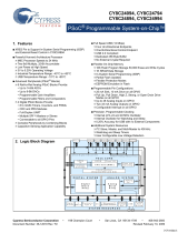
4. Hardware 23
4.1 System Block Diagram ..............................................................................................23
4.2 Functional Description ...............................................................................................24
4.2.1 PSoC CY8C24849 Chipset............................................................................25
4.2.2 USB Mini B Connector...................................................................................25
4.2.3 ISSP Programming Header............................................................................26
4.2.4 GPIO Pins......................................................................................................27
4.2.5 I2C Slave Interface Connector.......................................................................28
4.2.6 Demo Target Board........................................................................................29
5. Example Projects 31
5.1 Example Project 1: I2C-USB Demo Target Board Project.........................................31
5.1.1 Project Description.........................................................................................31
5.1.2 Hardware Connections...................................................................................32
5.1.3 I2C-USB Demo Target Board Flowchart........................................................33
5.1.4 Verify Output ..................................................................................................34
5.2 Example Project 2: I2C-USB Bridge Board Project ...................................................34
5.2.1 Project Description.........................................................................................34
5.2.2 Hardware Connections...................................................................................35
5.2.3 I2C-USB Bridge Flowchart.............................................................................36
5.2.4 Verify Output ..................................................................................................38
[+] Feedback

4 CY3240-I2USB I2C-USB Bridge Guide, Doc. # 001-66660 Rev.**
Contents
A. Appendix 39
A.1 Schematic..................................................................................................................39
A.1.1 I2C-USB Bridge Schematic............................................................................39
A.1.2 Demo Target Board Schematic......................................................................42
A.2 I2C-USB Bridge Board Layout...................................................................................43
A.2.1 Demo Target Board Layout............................................................................43
A.3 BOM ..........................................................................................................................44
A.3.1 I2C-USB Bridge BOM Rev. E ........................................................................44
A.3.2 Demo-Target Board R....................................................................................45
[+] Feedback

CY3240-I2USB I2C-USB Bridge Guide, Doc. # 001-66660 Rev.** 5
1. Introduction
Thank you for your interest in the CY3240-I2USB Kit. The CY3240-I2USB can be used with the
Bridge Control Panel that is installed with PSoC Programmer. The kit is designed to test, tune, and
debug programs that have an I2C slave interface. This document describes the working of CY3240
and includes example projects, which will help you get started with the bridging tool. You can also
develop custom programs using PERL, Python, C++, and C# languages. These custom applications
allow generating complex testing, debugging, and validation systems using PSoC Programmer
COM.
You can evaluate the kit using the example projects provided with the kit. The example projects help
to:
■ Explore I2C-USB communication between the PC and slave interfaced via I2C slave interface
connector of the bridge
■ Customize the designs provided along with the kit
The CY3240 I2C-USB Bridge board is configured with the I2C-USB Bridge Board example project
when shipped. See Chapter 5 for more details.
Chapter 2 of this document describes the installation and configuration of CY3240-I2USB. Chapter 3
explains the programming of a PSoC 1 device with PSoC Programmer and how to use the kit with
the help of an example project. Chapter 4 describes the hardware operation. Chapter 5 provides
instructions to create a simple example project. The Appendix section provides the schematics and
BOM for the CY3240-I2USB kit.
Evaluate the sample projects provided with the kit and then experiment with the kit hardware and
software to create your own designs.
1.1 Kit Contents
The CY3240-I2USB Bridge Kit contains:
■ I2C-USB Bridge
■ I2C demo target board
■ USB A to Mini B cable
■ CY3240-I2USB kit CD
Inspect the contents of the kit. If any parts are missing, contact your nearest Cypress sales office for
further assistance.
1.2 Bridge Control Panel Software
Bridge Control Panel is installed along with PSoC Programmer and enables the bridge to communi-
cate with the PC. It is used to send and receive data from the device connected to the bridge.
[+] Feedback

6 CY3240-I2USB I2C-USB Bridge Guide, Doc. # 001-66660 Rev.**
Introduction
1.3 Additional Learning Resources
Visit www.cypress.com for additional learning resources in the form of data sheets, technical
reference manual, and application notes.
■ Application Note - Using Cypress I
2
C Port Expander with Flash Storage:
http://www.cypress.com/?rID=2694
■ PSoC CY8C24894 - Features and Chip functionality:
http://www.cypress.com/?rID=37765
■ PSoC CY8C21123 - Features and Chip functionality:
http://www.cypress.com/?rID=3335
■ For more information regarding PSoC Designer functionality and releases:
www.cypress.com/go/psocdesigner
■ For more information regarding PSoC Programmer, supported hardware and COM layer:
www.cypress.com/go/psocprogrammer
■ For a list of PSoC Designer-related trainings:
http://www.cypress.com/?rID=40543
1.4 Document History
1.5 Documentation Conventions
Revision
PDF Creation
Date
Origin of
Change
Description of Change
** 01/25/2011 RKPM Initial version of kit guide
Table 1-1. Document Conventions for Guides
Convention Usage
Courier New
Displays file locations, user entered text, and source code:
C:\ ...cd\icc\
Italics
Displays file names and reference documentation:
Read about the sourcefile.hex file in the PSoC Designer User Guide.
[Bracketed, Bold]
Displays keyboard commands in procedures:
[Enter] or [Ctrl] [C]
File > Open
Represents menu paths:
File > Open > New Project
Bold
Displays commands, menu paths, and icon names in procedures:
Click the File icon and then click Open.
Times New Roman
Displays an equation:
2 + 2 = 4
Text in gray boxes Describes cautions or unique functionality of the product.
[+] Feedback

CY3240-I2USB I2C-USB Bridge Guide, Doc. # 001-66660 Rev.** 7
2. Getting Started
This chapter describes the installation and configuration of CY3240-I2USB.
2.1 CD Installation
To install the kit software, follow these steps:
1. Insert the kit CD into the CD drive of your PC. The CD is designed to auto-run and the kit installer
startup screen appears.
Note You can also download the latest kit installer from http://www.cypress.com/go/CY3240-
I2USB. Download the ISO file and create an installer CD or extract the ISO using WinRar and
install the executables.
2. Click Install CY3240-I2USB Bridge Kit to start the installation, as shown in Figure 2-1.
Figure 2-1. CY3240-I2USB Menu
Note If auto-run does not execute, double-click cyautorun.exe file on the root directory of the
CD, as shown in Figure 2-2.
[+] Feedback

8 CY3240-I2USB I2C-USB Bridge Guide, Doc. # 001-66660 Rev.**
Getting Started
Figure 2-2. Root Directory of CD
3. On the startup screen, click Next to start the installer.
4. In the InstallShield Wizard, choose the folder location to install the setup files. You can change
the location of the folder for the setup files using Change, as shown in Figure 2-3.
5. Click Next to launch the installer.
Figure 2-3. InstallShield Wizard
6. On the Product Installation Overview screen, select the installation type that best suits your
requirement. The drop-down menu has three options: Typical, Complete, and Custom, as
shown in Figure 2-4.
7. Click Next to start the installation.
[+] Feedback

CY3240-I2USB I2C-USB Bridge Guide, Doc. # 001-66660 Rev.** 9
Getting Started
Figure 2-4. Installation Type Options
8. When the installation begins, a list of packages appears on the Installation Page.
9. A green checkmark appears against every package that is downloaded and installed, as shown
in Figure 2-5.
10.Wait until all the packages are downloaded and installed successfully.
Figure 2-5. Installation Page
[+] Feedback

10 CY3240-I2USB I2C-USB Bridge Guide, Doc. # 001-66660 Rev.**
Getting Started
11.Click Finish to complete the installation, as shown in Figure 2-6.
Figure 2-6. Installation Complete Page
After the software installation, verify that you have all hardware and drivers set up for the I2C-USB kit
by connecting the bridge to your PC via its USB interface. Because this is the first time you have
connected this board to the PC, initial drivers are installed. Follow the instructions to complete the
installation process. Also, verify your installation by opening PSoC Programmer with the kit board
attached to USB.
2.2 PSoC Designer
PSoC Designer 5.1 is the revolutionary integrated design environment (IDE) that helps to customize
PSoC to meet specific application requirements. PSoC Designer software accelerates system bring-
up and time-to-market.
■ To open PSoC Designer, click Start > Programs > Cypress > PSoC Designer 5.1 >
PSoC Designer 5.1
■ To create a new project, click File > Create New Project
■ To open an existing project, click File > Open
■ To experiment with the example projects, go to Example Projects on page 31
[+] Feedback


12 CY3240-I2USB I2C-USB Bridge Guide, Doc. # 001-66660 Rev.**
Getting Started
2.3 PSoC Programmer
To open PSoC Programmer, click Start > Programs > Cypress > PSoC Programmer 3.12 >
PSoC Programmer 3.12.
To successfully program the device, follow these steps:
1. Select the I2C-USB bridge in Port Selection, as shown in Figure 2-8.
Figure 2-8. PSoC Programmer Window
2. Click the File Load button to load the hex file.
3. Click the Program button to program the hex file on the chip.
4. Close PSoC Programmer.
2.4 Bridge Control Panel
The Bridge Control Panel is used with CY3240 I2C-USB Bridge to enable communication with I2C
slave devices. This program is used to configure I
2
C devices and also to acquire and process data
received from I2C slave devices. The Bridge Control Panel helps in optimizing, debugging, and cali-
brating the target application.
1. Click Start > Programs > Cypress > Bridge Control Panel 1.2 > Bridge Control Panel
2. Select Power Supply, as highlighted in Figure 2-9.
3. Select the port connectivity.
[+] Feedback


CY3240-I2USB I2C-USB Bridge Guide, Doc. # 001-66660 Rev.** 15
3. Kit Operation
3.1 Introduction
The device meets the requirements of I2C Specification for standard and fast speed I
2
C devices,
and supports USB HID devices. The bridge is powered by the USB and consumes less than
500 mA. The device can be configured for several I
2
C clock rates such as 50 kHz, 100 kHz, and
400 kHz.
The number of devices that can be connected is constrained only by the I
2
C address limit and phys-
ical ability of the I
2
C bus. For more details, see the I2C Specifications.
The USB communication function uses two 64-byte packets: one for input data flow and the other for
output data flow. The maximum bandwidth of this configuration is 64 bytes. This is sufficient for most
I2C-USB bridge applications (Figure 3-1).
Figure 3-1. I2C-USB Bridge
[+] Feedback

16 CY3240-I2USB I2C-USB Bridge Guide, Doc. # 001-66660 Rev.**
Kit Operation
3.2 Connect Bridge to Device
Figure 3-2. Bridge to Device Connection
Perform the following steps to connect the device to I2C-USB bridge, as shown in Figure 3-2:
1. Connect GND of the device to GND of the bridge.
2. Connect the SDA and SCL lines to the bridge.
Bridge has 2.2 k pull-up resistors connected to +5 V. The INT pin is a pull-down bidirectional pin
that can be used as an additional signal between the bridge and I
2
C slave device for functions
such as sleep mode control.
3. Power the device from the Vdd pin on the bridge, if it does not have its own power supply. Note
that the Vdd connection between the bridge and target board is required, even if the board is self-
powered. Optionally, the bridge can provide 3.3 V or 5 V, or work with an externally powered
board using 2.4 V to 5.6 V.
4. When the connection between the bridge and USB is successful, the LED (green) lights up, as
shown in Figure 3-3.
Figure 3-3. Connecting Bridge to USB.
5. Open the Bridge Control Panel from the PC to work with the bridge.
3.2.1 Program I2C-USB Bridge
The CY3240 I2C-USB Bridge can be programmed using a MiniProg at the programming header of
the bridge. To use MiniProg, use the ISSP Programming Header (J2) on the board as highlighted in
Figure 3-4.
[+] Feedback

CY3240-I2USB I2C-USB Bridge Guide, Doc. # 001-66660 Rev.** 17
Kit Operation
Figure 3-4. ISSP Programming Header
3.3 Connect Demonstration Board to Bridge
1. Connect I2C slave demonstration board to bridge, as shown in Figure 3-5.
Figure 3-5. Demonstration Board and Bridge Connection
2. Select +5V as power supply to the board from Bridge Control Panel. The LED (red) on the bridge
board lights up, as shown.
Figure 3-6. LED (Red) on the Bridge Board
3. Click List; the bridge will find I2C slave demonstration board at 0x00 address.
3.3.1 Run Demonstration Board Test
The demonstration board has built-in temperature sensor and photodiode. The measurement results
of these are sent over I
2
C.
1. Open the Variable Setting dialog box from the Chart menu.
[+] Feedback

18 CY3240-I2USB I2C-USB Bridge Guide, Doc. # 001-66660 Rev.**
Kit Operation
Figure 3-7. Variable Setting Box
2. Load the demo.ini file by clicking the Load button, as shown in Figure 3-7. The demo.ini file ini-
tializes light and temperature variables and is available in the CY3240-I2USB kit CD or at the fol-
lowing location: <Installed_directory>:\Cypress\CY3240-I2USB.
3. Load demo.iic file for iic commands that can be sent to demo target board; the demo.iic file is
available in the CY3240-I2USB kit CD or at the following location:
<Installed_directory>:\Cypress\CY3240-I2USB
Go to File > Open File > demo.iic to select the file.
4. The first two lines in the demo.iic file show how to control the LEDs on the board. Position the
cursor in the first line and press [Enter] to send the command. Repeat for the second command
line. Observe that, on sending the first command, the LED1 turns off. The second command
reduces the LED intensity by 50 percent.
[+] Feedback

CY3240-I2USB I2C-USB Bridge Guide, Doc. # 001-66660 Rev.** 19
Kit Operation
Figure 3-8. Bridge Control Panel Editor Screen View
5. Click in the last line, which reads temperature and light data from the device and then click the
Repeat button. On clicking Repeat, the command that is sent last is repeated until Stop is
clicked. This makes data collection easier. The data received from slave can be viewed either
graphically or in a tabular form.
6. Click the Chart tab to view data graphically, as shown in Figure 3-9.
[+] Feedback

/