Page is loading ...

1
IMPORTANT:
Go to www.extron.com for the complete
user guide, installation instructions, and
specifications before connecting the
product to the power source.
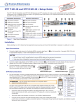
IN1808 Series • Setup Guide
The Extron IN1808 Series are eight-input seamless scaling presentation switchers that support signal resolutions up to
4K @ 60 Hz at 4:4:4. They feature DisplayPort, HDMI, and DTP2 inputs, HDMI output and a mirrored Extron DTP2 output
extension to send video, audio, and control signals up to 330 feet (100 meters) over a shielded CATx cable. The IN1808 IPCP SA
and IN1808 IPCP MA 70 models each have a built-in Extron IPCP Pro 355M IP Link Pro Control Processor, and an integrated
100 watt class D power amplier. The IN1808 Series delivers high image quality, fast and reliable switching, Extron ProDSP audio
processing, seamless video transition effects, logo keying, and HDMI loop out. The scalers can be controlled and congured over
Ethernet, RS-232, or USB.
This guide provides instructions for an experienced user to set up and congure the IN1808 (base model), IN1808 IPCP SA,
and IN1808 IPCP MA 70 scalers. It covers how to perform basic operations using the front panel controls and selected Simple
Instruction Set (SIS™) commands.
NOTES:
• For full installation, configuration, menus, connector wiring, and operation details, see the IN1806 and IN1808
Series User Guide at www.extron.com. For installation, configuration, and operation details of the embedded
IPCP Pro 355M, see the IPCP Pro Series User Guide.
• The IN1808 Series products can also be configured via the Extron Product Configuration Software (PCS), available at
www.extron.com. For information on using PCS, see the IN1806 and IN1808 Series Help File.
Installation
IN1808 Series Rear Panel Connectors
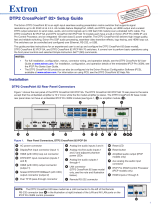
Figure 1 shows the rear panel of the IN1808 IPCP SA rear panel. The IN1808 IPCP MA 70 rear panel is the same except that
the embedded amplier is mono while the SA model amplier is stereo. The IN1808 base model rear panel does not have an
embedded IPCP Pro 355M module (see gure 1,
P
) or amplier module (
N
).
2x25W(8Ω)/2x50W(4Ω)
LR
CLASS 2 WIRING
AMPLIFIED OUTPUT
OUTPUTS (DTP/XTP/HDBT) AUDIO INPUTS OUTPUTS
HDMI/CEC
OVER TP
1A 1B
SIG LINK
OUT
Tx Rx
IR
G
12
34
+48V
+48V
1
2
MIC/LINE
LR
AUX
34
INPUTS (DTP2/XTP)
LOOP OUT
31
2
5
4 6
7
SIG LINK
IN
8
SIG LINK
IN
REMOTE
Tx Rx
RS-232
G
RESET
100-240V~1.5A MAX
50-60 Hz
IN1808 IPCP SA
LAN
AV LAN 2
AV LAN 3
AV LAN 1
Tx Rx
RTSCTS
G
Tx Rx GTxRxG
R
1234G
DIGITAL I/OCOM 3COM 2COM 1
SSGG
1
1
2
2
C34C
+S G-S+V
PWR OUT = 6W
RRRRRRRRRR
R
R
R
R
R
R
R
R
R
R
R
R
R
IR/SERIAL eBUSRELAYS
A
C
H
B
O
E
F
G
J
K
L
NQ
P
D
M
I
Figure 1. Rear Panel Connectors, IN1808 IPCP SA
A
AC power connector
B
DisplayPort input connector (input 1)
C
HDMI (with CEC) loop out connector
D
DTP2/XTP input connectors (inputs 7
and 8)
E
HDMI (with CEC) output connector (1A)
F
DTP2/XTP/HDBaseT (with CEC) output
connector (1B)
G
Over TP IR pass-through connector
H
Analog line audio inputs 3 and 4
I
Analog mic/line audio inputs 1
and 2 and adjacent phantom
power LEDs
J
Analog line audio outputs 1
through 4
K
Remote RS-232 port
L
Reset LED
M
Reset button
N
Amplified audio output (IPCP models
only)
o
Aux mono or stereo analog line
audio input connector
P
IPCP Pro 355M Control Processor
(IPCP models only)
Q
HDMI inputs 2 through 6
R
LAN connector (IN1808 base model
only, see the note and illustration
below)
NOTE: The IN1808 base model has a LAN connector to the left of the Remote RS-232 connector
(see
R
in the illustration at right) instead of the AV LAN ports on the IPCP Pro 355M control
processor.
100-240V 50/60 Hz
--A MAX
31
2
5
4 6
HDMI/CEC
INPUTS OUTPUTS AUDIO INPUTS
OUTPUTS REMOTE
OVER TP
IN1808
7
SIG LINK
IN
81A
DTP2/XTP II
SIG LINK
IN
1B
SIG LINK
OUT
DTP2/XTP/HDBT
LOOP OUT
Tx Rx
RS-232
G
Tx Rx
IR
G
RESET
12
34
+48V
+48V
1
2
MIC/LINE
LR
AUX
34
LAN
100-240V 50/60 Hz
--A MAX
31
2
5
4 6
HDMI/CEC
INPUTS OUTPUTS AUDIO INPUTS
OUTPUTS REMOTE
OVER TP
IN1808
7
SIG LINK
IN
81A
DTP2/XTP
SIG LINK
IN
1B
SIG LINK
OUT
DTP2/XTP/HDBT
LOOP OUT
Tx Rx
RS-232
G
Tx Rx
IR
G
RESET
12
34
+48V
+48V
1
2
MIC/LINE
LR
AUX
34
LAN
R

2
IN1808 • Setup Guide (Continued)
Mounting and Cabling
Step 1 — Mount the device
a. Turn off or disconnect all equipment power sources.
b. Mount the IN1808 to a rack using the pre-installed side mounting brackets, or remove the brackets and use an optional
19-inch rack under-desk mounting kit (see the mounting instructions provided with the kit, available at www.extron.com).
The IN1808 base model has a 1U high, full rack wide enclosure. The IN1808 IPCP models have 2U, full rack enclosures.
Step 2 — Connect inputs
Make the following input connections as needed:
• Connect a DP source to the Input 1 DisplayPort connector (see figure 1,
B
, on the previous page).
• Connect HDMI or DVI (with an appropriate adapter) sources to HDMI input connectors 2 through 6 (
Q
).
• Connect DTP transmitters to the DTP2/XTP RJ-45 input connectors 7 and 8 (
D
). These connectors allow for remote
powering of DTP transmitters. You can configure the TP inputs for XTP mode via SIS commands, the on-screen
display (OSD), or PCS (see the IN1808 Series Help File). For cable wiring and recommendations, see Twisted Pair
Recommendations for DTP, XTP, and HDBaseT Communication on the next page.
• Connect analog audio sources to:
• The 5-pole captive screw line audio input connectors 3 and 4 (
H
) and the Aux connector (
O
) for balanced or
unbalanced stereo audio. The Aux Line input is shared and can be associated with one or more video inputs.
• Connect balanced or unbalanced mic or line level inputs to 3-pole Mic/Line captive screw connectors 1 and 2 (
I
).
These inputs support optional +48 VDC phantom power, which is indicated by the LEDs at the left of the connectors.
Step 3 — Connect outputs
Make the following output connections as needed:
• Connect an HDMI, or DVI with an appropriate adapter, display to HDMI/CEC output connector 1A (
E
).
• Connect a DTP/XTP matrix switcher/HDBaseT compatible receiver to output connector 1B (
F
). For cable wiring and
recommendations, see Twisted Pair Recommendations for DTP, XTP, and HDBaseT Communication.
• To pass infrared data, connect a control device to the 3-pole IR Over DTP captive screw connector (see IR Over TP Wiring
on the next page). Alternatively, insert RS-232 communication to a DTP/HDBaseT endpoint via Ethernet (see the IN1808
Series User Guide for more information).
• Connect balanced or unbalanced analog audio output devices to one or both 5-pole captive screw output connector pairs
1 and 2 or 3 and 4 (
J
). See Audio Wiring on the next page for more information.
• For IPCP models, connect speakers to the amplifier module via the 5 mm 4-pole stereo (IN1808 IPCP SA) or 2-pole mono
(IN1808 IPCP MA 70) Amplified Output connector (
N
).
Step 4 — Connect control devices
• To control the base model through Ethernet, connect a LAN or WAN to the LAN connector (
R
). To wire the RJ-45 connector
to the cable, see Twisted Pair Recommendations for DTP, XTP, and HDBaseT Communication.
For the IPCP models, connect a LAN or WAN to any of the AV LAN connectors on the IPCP Pro control processor (
P
). The
default IP address of the scaler is 192.168.254.254. The default subnet mask is 255.255.255.0. The default gateway address
is 0.0.0.0.
• For serial RS-232 control, connect a host device to the 3-pole captive screw connector (
K
). The default baud rate is 9600.
• For control through USB, connect a host device to the front panel USB mini-B port (see figure 2,
H
on page 4).
Step 5 — Set up the IPCP Pro 355M control processor (IPCP models only)
The Extron IPCP Pro 355M control processor (see figure 1,
P
) provides monitoring and control of a variety of external devices,
such as projectors and lights. See the IPCP Pro Series Setup Guide, available at www.extron.com, for installation details.
Step 6 — Connect power
Connect a 100 to 240 VAC, 50-60 Hz power source to the AC power connector (
A
).

3
Twisted Pair Recommendations for DTP, XTP, and HDBaseT Communication
Extron recommends using the following practices to achieve full transmission distances
and reduce transmission errors:
• Use Extron XTP/DTP 24 SF/UTP cable for the best performance. At a minimum, Extron
recommends 24 AWG, solid conductor, STP cable with a minimum bandwidth of
400 MHz.
• Terminate cables with shielded connectors to the TIA/EIA-T568B standard (shown at
right).
• Limit the use of more than two pass-through points, which may include patch points,
punch down connectors, couplers, and power injectors. If these pass-through points
are required, use shielded couplers and punch down connectors.
ATTENTION:
• Do not connect these connectors to a telecommunications or computer data
network.
• Ne connectez pas ces ports à des données informatiques ou à un réseau de
télécommunications ou de données informatiques.
• DTP remote power is intended for indoor use only. No part of the network that
uses DTP remote power should be routed outdoors.
• L’alimentation DTP à distance est destiné à une utilisation en intérieur
seulement. Aucune partie du réseau qui utilise l’alimentation DTP à distance ne
peut être routée en extérieur.
NOTE: When using shielded twisted pair cable in bundles or conduits, consider the following:
• Do not exceed 40% fill capacity in conduits.
• Do not comb the cable for the first 20 meters, where cables are straightened, aligned, and secured in tight bundles.
• Loosely place cables and limit the use of tie wraps or hook-and-loop fasteners.
• Separate twisted pair cables from AC power cables.
Audio Wiring
Wire the audio input and output connectors as shown at right. Use
the supplied tie wrap to strap the audio cable to the extended tail
of the connector. This does not apply to the amplied audio output
connector on the SA and MA models.
ATTENTION:
• For unbalanced outputs, do not connect wires to the
“-” poles (see the illustration at right).
• Pour les sorties asymétriques, ne connectez pas de
câbles aux pôles «-» (voir l’illustration de droite).
NOTE: The length of exposed wires is critical. The ideal length
is 3/16 inch (5 mm).
IR Over TP Wiring
To transmit and receive IR signals, connect a control device to the
three-pole Over TP IR connector (G, Tx, and Rx).
NOTE: RS-232 data can be inserted via Ethernet only (see the
IN1806 and IN1808 Series User Guide for details).
TIA/EIA-T568B
Pin Wire Color
1 White-orange
2 Orange
3 White-green
4 Blue
5 White-blue
6 Green
7 White-brown
8 Brown
12345678
RJ-45
Connector
Insert Twisted
Pair Wires
Pins:
Balanced Audio Output
Tip
Ring
Tip
Ring
Slee
ves
Unbalanced Audio Output
Tip
No Ground Here
No Ground Here
Tip
Sleeves
LR
LR
Unbalanced Audio InputBalanced Audio Input
Tip
Ring
Tip
Ring
Sleeves
Tip
Sleeve
Sleeve
Tip
LR
LR
Do not tin the wires!
A
udio Inputs and Outputs 1 – 4 and Aux
Mic/Line Inputs 1 and
2
Balanced Audio Input
Tip
Slee
ve
Ring
Unbalanced Audio Input
Tip
Sleeve

4
IN1808 • Setup Guide (Continued)
Front Panel Overview
Figure 2 shows the front panel of the IN1808 IPCP SA and IPCP MA 70. The IN1808 base model is 1U high and has no IPCP Pro
LEDs (
H
).
A
B
EF
H
G
C
D
Figure 2. Front Panel Features, IN1808 IPCP SA and IN1808 IPCP MA 70
A
Config port
B
Input selection buttons (1 through 8)
C
Logo button
D
Signal and Status LEDs
E
Menu and Enter buttons
F
Navigation buttons
G
Mic and Volume knobs and LEDs
H
IPCP Pro LEDs (IPCP models only)
A
Front panel configuration port — Connect a host device to the USB mini-B port for device configuration, control, and
firmware upgrades
B
Input selection buttons (1 through 8) — Press one of these buttons to select an input. The buttons light amber for audio
and video, green for video only, or red for audio only.
C
Logo button — Press this button to enable or disable the most recently selected logo slot. Press and hold the button to
select logo slot 1 through 8 using the input selection buttons (slots 9-16 are available via SIS commands only). See the
IN1806 and IN1808 Series User Guide at www.extron.com for more information about logos.
D
Status LED indicators
• Input signal LEDs — These eight LEDs light green for their corresponding inputs when active video content is detected
on that input.
• Output signal LEDs — Output LEDs 1A, 1B, and Loop light green when active video is being output, and blink amber
when output video and sync are disabled.
• Input HDCP LEDs — These eight LEDs light green for each input signal that is HDCP-encrypted.
• Output HDCP LEDs — These three LEDs light green for an output when it is currently HDCP-encrypted.
• DTP2 and DTP Input LEDs — These two LEDs light green if DTP or DTP2 power has been enabled on the
corresponding input.
• DTP2 and DTP Output LEDs — These Output LEDs light green if DTP or DTP2 power has been enabled on DTP
output 1B.
E
Menu and Enter buttons — Press these buttons to access and navigate the on-screen display menu system.
F
Navigation buttons — Press these buttons to navigate through the on-screen display menu system or change settings.
G
Mic and Volume knobs and LED indicators — Rotate the Mic knob to adjust the microphone level. Rotate the Volume
knob to adjust the program or output volume level (configurable, see the IN1806 and IN1808 Series PCS Help File for more
information). The eight LED indicators for each knob light according to the level being adjusted. The LEDs light in order from
bottom to top to indicate steps from 1% (-99 dB) to 99% (-1 dB). The bottom LED blinks when the volume is muted. The top
LED blinks when the volume is at 100% (12 dB).
H
IPCP Pro LED indicators — IPCP models only (see the IPCP Pro Series Setup Guide for details).
Firmware Updates
Download rmware updates from the Extron website and upload them via the internal web pages or PCS.

5
IN1808 Series Configuration
To congure IN1808 Series, use the front panel controls, the
on-screen display (OSD) menu, internal web pages, PCS, or SIS
commands.
On-screen Display (OSD) Menu System
To congure IN1808 Series using the OSD menu, connect a display
to either HDMI output 1A or to a DTP/XTP matrix switcher/HDBaseT
compatible device. The OSD menu consists of eight submenus accessed
using the front panel Menu or Enter button (see the example at right).
Extron Product Configuration Software
To congure IN1808 scalers using PCS, install the software (available on
the Extron website, www.extron.com) to a PC connected to the scaler
via Ethernet or front panel USB Cong port. After the installation, start the
program. For full instructions, press <F1> on the keyboard or click the ?
button in the software and select Help File.
Internal Web Pages
To congure the IN1808 Series using the factory-installed web pages in a web browser (see the example at right), connect the
AV LAN connector (IPCP models) or LAN connector (base model) on the IN1808 to a LAN or WAN. The default IP address is
192.168.254.254.
Basic SIS Command Table
To congure IN1808 Series with specic SIS commands via an RS-232, USB, or Ethernet connection, use the Extron DataViewer
utility or a control system to send and receive SIS commands. The table below lists a selection of SIS commands. For a full list of
SIS commands and variables, see the IN1806 and IN1808 Series User Guide at www.extron.com.
Command ASCII Command Response Additional Description
Input Selection
Select audio and video input
X!*1! InX!*1
•
All] Select audio and video from input X! to the output.
Select video input only
X!*1% InX!
•
1Vid] Select the video only from input X! to the output.
Select audio input only
X!*1$ InX!
•
1Aud] Select the audio only from input X! to the output.
Auto-Image
Execute Auto-Image™
1*0A
Img*0
]
Execute an Auto-Image (follows aspect setting).
Execute Auto-Image and ll
1*1A
Img*1
]
Execute an Auto-Image and ll the output raster.
Execute Auto-Image and follow
1*2A
Img*2
]
Execute an Auto-Image and follow the input aspect ratio.
Auto-Switch Mode
Set Auto-Switch mode
EX3) AUSW} AuswX3)] Select Auto-Switch mode X3).
View Auto-Switch mode
EAUSW} X3)]
View the current Auto-Switch mode.
Set Auto-Switch priority
EPX3!
1
... X3!
8
AUSW} Ausw PX3!
1
... X3!
8
] Set priority X3! for input selection. Lists inputs in order of
priority, from highest to lowest.
View Auto-Switch priority
EP AUSW} X3!
1
... X3!
8
]
View Auto-Switch priority. Lists inputs in order of priority,
from highest to lowest.
View memory priority
EO AUSW} X3!
1
... X3!
8
]
View Auto-Switch memory priority, from highest to lowest
Output Scaler Rate
Set output rate
E1*X2!RATE} Rate1*X2!] Select output resolution and refresh rate X2!.
View output rate
E1RATE} X2!]
View the output rate.
KEY:
X! = Input selection 1 through 8
X2! = Output resolution and rate See the EDID Emulation and Output Rate table in the IN1806 and IN1808 Series User Guide.
X3) = Auto-Switch mode 0 = disabled (default), 1 = user defined priority, 2 = input memory priority (most recently
detected input)
X3! = Input numbers for Auto-Switch priority 1 through 8

6
68-3131-51 Rev. A
02 19
© 2019 Extron Electronics — All rights reserved. www.extron.com All trademarks mentioned are the property of their respective owners.
Worldwide Headquarters: Extron USA West, 1025 E. Ball Road, Anaheim, CA 92805, 800.633.9876
Command ASCII Command Response Additional Description
Video Mute
Mute output video
X@*1B VmtX4@*1] Mute the video on output X@.
Mute video on all outputs
1B
Vmt1]
Mute the video on all outputs.
Mute video and sync
2B
Vmt2]
Mute the video and sync on all outputs.
Unmute video and sync
0B
Vmt0]
Unmute the video on all outputs.
View output mute status
B
VmtX4@
1
•X4@
2
•X4@
3
] View mute status X4@ for outputs 1A (1), 1B (2), and loop
(3).
Audio Configuration
Set audio input format
EIX!*X5*AFMT} AfmtIX!*X5*]
Set the audio format of input X! to X5*.
View audio input format
EIX!AFMT} X5*]
View the audio format of input X!.
Front Panel Lockout (Executive Modes)
Enable lock mode 1
1X
Exe1]
Lock all front panel controls.
Enable lock mode 2
2X
Exe2]
Lock the front panel except for input selection, logo
conguration, and volume adjustment.
Enable lock mode 3
3X
Exe3]
Lock the front panel except for input selection and logos.
Enable lock mode 4
4X
Exe4]
Lock the front panel except for volume adjustment.
Disable executive modes
0X
Exe0]
Allow all front panel adjustments and selections.
IP Settings
Set scaler IP address
EX8&CI} Ipi
•
X8&]
Species a new scaler IP address.
Set scaler DHCP mode
EX( DH} IdhX(]
Enables or disables DHCP (0 = default).
Set subnet mask
EX8*CS} Ips
•
X8*]
Species a new subnet mask.
Set gateway IP address
EX8(CG} Ipg
•
X8(]
Species a new gateway IP address.
Reboot network
E2BOOT} Boot2]
Restarts the network connection after IP or DHCP
changes.
NOTE: IP settings do not take effect until the E2BOOT} command is executed.
Twisted Pair Protocol
Set input TP type
EIX!*X6&HDBT} HdbtIX!*X6&] Set the DTP/XTP type for input X! to X6&.
View input TP type
EIX!HDBT} X6&] View the current DTP/XTP type for input X!.
Set output TP type
EO 2*X6&HDBT} Hdbt O 2*X6&] Set the TP type for input X! to X6&.
View output TP type
EO 2 HDBT} X6&] View the DTP/XTP/HDBT setting X6& on output 1B.
DTP Remote Power Parameters
Set input remote power
EIX!*X6^RPWR}
RpwrIX!*X6^]
Set remote power on input X! to X6^.
View input remote power
EIX!RPWR}
X6^]
View remote power setting on input X!.
Set output 1B remote power
EO 2*X6^RPWR}
RpwrO 2*X6^]
Set remote power on output 1B to X6^.
View output 1B remote power
EOX@RPWR}
X6^]
View remote power setting on output .
KEY:
X! = Input selection Inputs 1 through 8. For the Twisted Pair Protocol commands, X! = Inputs 7 and 8 only.
X@ = Output selection 1 = Output 1A (HDMI/DVI), 2 = Output 1B / 2 DTP/XTP/HDBT, 3 = Loop Output – HDMI/DVI
X1) = Enable or disable 0 = off or disabled, 1 = on or enabled)
X6^ = DTP remote power 0 = Off (No remote power, default), 1 = DTP 12 VDC, 2 = DTP2 48 VDC
X4@ = Video mute status 0 = unmuted, 1 = muted
X5* = Audio input type 0 = None (input muted), 1 = Analog aux line (5-pole captive screw), 2 = LPCM-2Ch digital, 3 = Multi-Ch digital,
4 = LPCM-2Ch digital audio aux line (default), 5 = Multi-Ch digital auto aux line.
X6& = TP format 0 = DTP format (default), 1 = XTP, 2 = HDBaseT format (supported on output only)
X8& = IP address nnn.nnn.nnn.nnn), 192.168.254.254 = default
X8* = Subnet mask nnn.nnn.nnn.nnn), 255.255.255.0 = default
X8( = Gateway address nnn.nnn.nnn.nnn), 0.0.0.0 = default
For information on safety guidelines, regulatory compliances, EMI/EMF compatibility, accessibility, and related topics, see the
Extron Safety and Regulatory Compliance Guide on the Extron website.
/